Research Article Volume 6 Issue 1
National Research University of Electronic Technology, MIET, Moscow, Russia
Correspondence: Afonin SM, National Research University of Electronic Technology, MIET, 124498, Moscow, Russia
Received: October 28, 2022 | Published: November 11, 2022
Citation: Afonin SM. Piezoengine for nanomedicine and applied bionics. MOJ App Bio Biomech. 2022;6(1):30-33. DOI: 10.15406/mojabb.2022.06.00164
Keywords: piezoengine, structural scheme, nanomedicine and applied bionics
A piezoengine is used for nano displacement in tunnel microscopy, for the nano alignment in adaptive optics, microscopy and interferometers in nanomedicine and applied bionics, for the automatic adjustment of the constant optical parameter of the ring quantum generators, for the actively dampen mechanical vibrations in the laser system, for the deform mirrors and operations with penetration in a cells and for the works with a genes.1–15 A piezoengine with a compact design provides positioning of elements of adaptive systems with an accuracy of up to a nanometer in the range of hundreds of nanometers. These precise parameters of a piezoengine are provided by the use of the reverse piezoelectric effect.16–48 To calculate the deformations of nano systems, it is required to build the structural scheme of a piezoengine. A piezoengine is used in adaptive optics systems for phase corrections, for example, in an interferometer to adjust maximum of the interference image. In scanning probe microscopy, an image of a surface is formed using a physical probe to scan an object. For example, a scanning tunneling microscope is used to visualize surfaces at the atomic level. Nano movements of the probe along three coordinates X, Y, Z are carried out using a piezoengines.14–23
A piezoengine works on basis of the reverse piezoelectric effect in the form3–52
Si=sEijTj+dmiEmSi=sEijTj+dmiEm
where SiSi , sEijsEij , TjTj , dmidmi , EmEm are the relative deformation, elastic compliance, strength mechanical field, piezomodule, strength electric field, i, j . m are indexes.
The differential equation is written4–52
d2Ξ(x,s)dx2−γ2Ξ(x,s)=0d2Ξ(x,s)dx2−γ2Ξ(x,s)=0
Here Ξ(x,s)Ξ(x,s) , s, xx , γγ are the transform of the deformation, the parameter of the Laplace transform, the coordinate, the propagation factor. For the transverse piezoengine we have at x=0x=0 the first deformation Ξ(0,s)=Ξ1(s)Ξ(0,s)=Ξ1(s) and at x=hx=h the second deformation Ξ(h,s)=Ξ2(s)Ξ(h,s)=Ξ2(s) .
The decision of the differential equation is obtained.
Ξ(x,s)={Ξ1(s)sh[(h−x)γ]+Ξ2(s)sh(xγ)}/sh(hγ)Ξ(x,s)={Ξ1(s)sh[(h−x)γ]+Ξ2(s)sh(xγ)}/sh(hγ)
Where Ξ1(s)Ξ1(s) , Ξ2(s)Ξ2(s) are the transforms of the deformations.
At x=0x=0 and x=hx=h we have the system for the transverse piezoengine
T1(0,s)=1sE11dΞ(x,s)dx|x=0−d31sE11E3(s)T1(0,s)=1sE11dΞ(x,s)dx∣∣x=0−d31sE11E3(s)
T1(h,s)=1sE11dΞ(x,s)dx|x=h−d31sE11E3(s)T1(h,s)=1sE11dΞ(x,s)dx∣∣x=h−d31sE11E3(s)
The mathematical model for the transverse piezoengine has the form.
Ξ1(s)=(M1s2)−1{−F1(s)+(χE11)−1×[d31E3(s)−[γ/sh(hγ)] ×[ch(hγ)Ξ1(s)−Ξ2(s)]]}
Ξ2(s)=(M2s2)−1{−F2(s)+(χE11)−1×[d31E3(s)−[γ/sh(hγ)]×[ch(hγ)Ξ2(s)−Ξ1(s)]]}
χE11=sE11/S0
At x=0 and x=l the system in general for a piezoengine is obtained.
Tj(0,s)=1sΨijdΞ(x,s)dx|x=0−νmisΨijΨm(s)
Tj(l,s)=1sΨijdΞ(x,s)dx|x=l−νmisΨijΨm(s)
Where l={ δ, h, b the length for the longitudinal, transverse or shift piezoengine.
Therefore, the mathematical model of a piezoengine is determined on Figure 1.
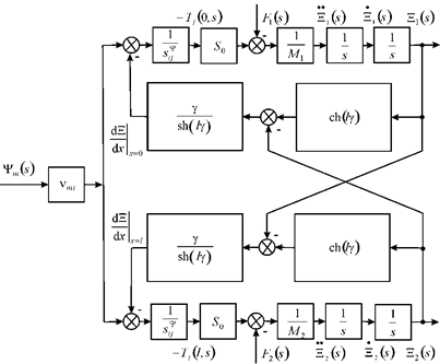
Ξ1(s)=(M1s2)−1{−F1(s)+(χΨij)−1×[νmiΨm(s)−[γ/sh(lγ)]×[ch(lγ)Ξ1(s)−Ξ2(s)]]}
Ξ2(s)=(M2s2)−1{−F2(s)+(χΨij)−1×[νmiΨm(s)−[γ/sh(lγ)]×[ch(lγ)Ξ2(s)−Ξ1(s)]]}
χΨij=sΨij/S0
Where
vmi={d33,d31,d15g33,g31,g15
Ψm={E3,E3,E1D3,D3,D1
sΨij={sE33,sE11,sE55sD33,sD11,sD55
γ={γE, γD
cΨ={ cE, cD
The mathematical model and the structural scheme of a piezoengine on Figure 1 are used for the design of a precise control system in nanomedicine and applied bionics.
The matrix of the deformations is written
(Ξ1(s)Ξ2(s))=(W11(s)W12(s)W13(s)W21(s)W22(s)W23(s)) (Ψm(s)F1(s)F2(s))
The settled longitudinal deformations are determined
ξ1=d33UM2/(M1+M2)
ξ2=d33UM1/(M1+M2)
For d 33 = 4×10⁻¹⁰ m/V, U = 125 V, M1 = 1 kg, M2 = 4 kg we have the settled deformations parameters ξ1 = 40 nm, ξ2 = 10 nm and ξ1+ξ2 = 50 nm at error 10%.
For the transverse piezoengine at one the fixed face the transfer expression is obtained
W(s)=Ξ(s)U(s)=kU31 T2ts2+2Ttξts+1
kU31=d31(h/δ)/(1+Cl/CE11)
Tt=√M/(Cl+CE11) , ωt=1/Tt
For M = 4 kg, Cl = 0.2×10⁷ N/m, CE11 = 1.4×10⁷ N/m we have the parameters Tt = 0.5×10⁻³ s, ωt = 2×10³ s-1 at error 10%.
The settled transverse deformation has the form
Δh=d31(h/δ)U1+Cl/CE11=kU31U
For d31 = 2∙10-10 m/V, h/δ = 20, Cl/CE11 = 0.14 the coefficient is determined kU31 = 3.5 nm/V at error 10%.
The mathematical model and the structural scheme of a piezoengine are constructed. The matrix of the deformations of a piezoengine is obtained. The parameters of a piezoengine are determined for the development of a precise control system in nanomedicine and applied bionics.
None.
None.
The authors declare that they have no conflict of interest.
©2022 Afonin. This is an open access article distributed under the terms of the, which permits unrestricted use, distribution, and build upon your work non-commercially.