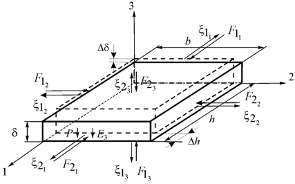
The deformation of the electroelastic actuator corresponds to its stressed state. In the piezoactuator there are six stress components
,
,
,
,
where the components
are related to extension–compression stresses and the components
to shear stresses. The matrix state equations8,11 connecting the electric and elastic variables for the polarized piezoceramics have the following form:
, (1)
, (2)
where the first equation describes the direct piezoelectric effect, and the second - the inverse piezoelectric effect;
is the column matrix of electric induction along the coordinate axes;
is the column matrix of relative deformations;
is the column matrix of mechanical stresses;
is the column matrix of electric field strength along the coordinate axes;
is the elastic compliance matrix for
;
is the matrix of dielectric constants for
;
is the transposed matrix of the piezoelectric modules.
In polarized piezoceramics from lead zirconate titanate PZT for the piezoactuator on Figure 1 there are five independent components
,
,
,
in the elastic compliance matrix, three independent components
,
,
in the transposed matrix of the piezoelectric modules and three independent components,
,
in the matrix of dielectric constants.

Let us consider the piezoactuator for the longitudinal piezoelectric effect, where
is thickness and the electrodes deposited on its faces perpendicular to axis 3, the area of which is equal
. The direction of the polarization axis Р, i.e., the direction along which polarization was performed, is usually taken as the direction of axis 3. The equation of the inverse longitudinal piezoelectric effect8,11 has the form:
, (3)
where
is the relative displacement of the cross section of the piezoactuator,
is the piezomodule for the longitudinal piezoeffect,
is the electric field strength,
c is the voltage between the electrodes of actuator,
is the thickness,
is the elastic compliance along axis 3, and
is the mechanical stress along axis 3.
The equation of equilibrium for the force acting on the piezoactuator on Figure 1 can be written as
, (4)
Where F is the external force applied to the piezoactuator,
is the cross section area and M is the displaced mass.
the equation of the inverse longitudinal piezoeffect, the wave equation using Laplace transform, the equations of the forces acting on the faces of the piezoactuator. The calculations of the piezoactuators are performed using the wave equation8,11,12 describing the wave propagation in the long line with damping but without distortions in the following form:
, (5)
where
is the displacement of the section, x is the coordinate, t is the time,
is the sound speed for ,
is the damping coefficient. We can reduce the original problem for the partial differential hyperbolic equation of type (5) using Laplace transform to a simpler problem for the linear ordinary differential equation[10,12]. Applying the Laplace transform to the wave equation (5)
, (6)
Setting the zero initial conditions we obtain the linear ordinary second–order differential equation with the parameter p in the form
, (7)
With its solution being the function
, (8)
Where
is the Laplace transform of the displacement of the section of the piezoelectric actuator,
is the propagation coefficient.
We denote for the faces of the piezoactuator
for ,(9)
for .
Then we get the coefficients C and B
,
, (10)
The solution (7) can be written as
, (11)
The equations for the forces on the faces of the piezoactuator
for
, (12)
for
,
Where
and
are determined from the equation of the inverse piezoelectric effect. For
and
, we obtain the set of equations for determining stresses in the piezoactuator:11−14
, (13)
.
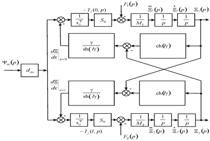
The set of equations (13) yield the set of the equations for the structural–parametric model of the piezoactuator and the parametric structural schematic diagram of the voltage–controlled piezoactuator for the longitudinal piezoelectric effect on Figure 2.
(14)
Where
.
From (2), (3), (14) we obtain the system of the equations describing the generalized structural–parametric model of the electroelastic actuator
(15)
where
,
,
,
,
,
,
, i = 1, 2…, 6, j = 1, 2, … , 6, m = 1, 2, 3,
Then the parameter
of the control parameter for the electroelastic actuator: E for the voltage control, D for the current control. On Figure 3 is shown the generalized parametric structural schematic diagram of the electroelastic actuator corresponding to the set (15) of the equations.

Figure 2 Parametric structural schematic diagram of a voltage-controlled piezoactuator for longitudinal piezoelectric effect.

Figure 3 Generalized parametric structural schematic diagram of the electroetoelastic actuator.
From the generalized structural–parametric model (15) of the electroelastic actuator after the algebraic transformations we obtain the transfer functions in matrix form.11−14 The transfer functions are the ratio of the Laplace transform of the displacement of the face for the electroelastic actuator and the Laplace transform of the corresponding control parameter or force at zero initial conditions.
, (16)
,
where the generalized transfer functions
,
,
,
.
From the set (15) of the equations we obtain the generalized matrix equation for the electroelastic actuator
. (17)
Let us find the displacement of the faces for the electroelastic actuator in the stationary regime for the inertial
load at
,
.
Then we get the static displacement of the faces for the electroelastic actuator
(18)
(19)
, (20)
where
is the mass of the electroelastic actuator,
are the load masses.
Let us consider the static characteristics of the piezoactuator from the piezoceramics PZT under the longitudinal piezoelectric effect at
and
. For
m/V,
V,
kg and
kg we obtain the static displacement of the faces of the piezoactuator
nm,
nm,
nm. The displacements in the stationary regime of the faces for the piezoactuator under the transverse piezoelectric effect and the inertial load at
,
,
can be written in the following form
(21)
(22)
. (23)
From (21), (22) we obtain the static displacements of the faces of the piezoactuator under the transverse piezoeffect at
,
in the form
(24)
(25)
Let us consider the static characteristics of the piezoactuator from piezoceramics PZT under the transverse piezoelectric effect at
and
. For
m/V,
m,
m,
V,
kg and
kg we obtain the static displacement of the faces of the piezoelectric actuator
nm,
nm,
nm.
From (16) we obtain the transfer functions of the piezoactuator with the fixed end and the elastic inertial load so that
and
in the following form
, (26)
where the time constant
and the damping coefficient
are determined by the formulas
,
.
Let us consider the operation of the piezoactuator from piezoceramics PZT with one face rigidly fixed and the elastic inertial load so that
and
for
kg,
N/m,
N/m we obtain
c. The experimental and calculated values for the piezoactuator are in agreement to an accuracy of 5%.


