The structural schemes of electroelastic engine micro and nano displacement are determined for applied bionics and biomechanics. The structural scheme of electroelastic engine is constructed by method mathematical physics. The displacement matrix of electroelastic engine micro and nano displacement is determined.
Keywords: electroelastic engine, structural scheme, micro and nano displacement, applied bionics
An electroelastic engines based on electroelasticity with piezoelectric and electrostriction effects are used for micro and nano displacement in applied bionics and biomechanics in adaptive optics, scanning microscopy, ring quantum generator, for the actively dampen mechanical vibrations, for penetration to a cells and for the works with a genes.1–15 An electroelastic engine is applied in adaptive optics systems for phase corrections in an interferometer to adjust maximum of the interference image. In scanning probe microscopy, an image of a surface is formed using an electroelastic engine to scan an object. Scanning tunneling microscope is used to visualize surfaces at the atomic level. Nano displacements of the probe along three coordinates X, Y, Z are carried out using an electroelastic engine.14–58
The equation of electroelastic effect3–49 is written in the general form
here
is control parameter and
at the voltage or current control,
are the relative displacement, the strength electric field, the electric induction, the strength mechanical field, the modules, and the elastic compliance at
the indexes i, j, m. The ordinary differential equation an electroelastic engine8–49 has form
here
,
, s,
are the transform of the displacement, the coordinate, the parameter, the propagation coefficient and the general length
an electroelastic engine. For an electroelastic engine at
and at
,
.
We have the solution this ordinary differential equation
here
are the transforms displacements of its two ends.
For the boundary conditions its system has the form
,
The transform of the force causes displacement is obtained
,
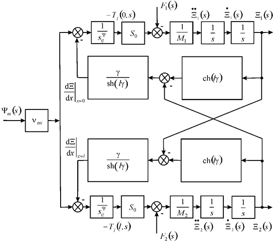
The general structural scheme of electroelastic engine on Figure 1 and its model are determined at voltage or current control for longitudinal, transverse and shift displacements

Figure 1 General structural scheme electroelastic engine.
here
,
The general structural scheme of electroelastic engine micro and nano displacement on Figure 1 are used for applied bionics and biomechanics
The displacement matrix has the form
,
here the transfer functions
At voltage control we have the equation of the direct piezoeffect in the form8–41
here k is the index,
is the permittivity. The direct coefficient of piezoengine at voltage control has the form
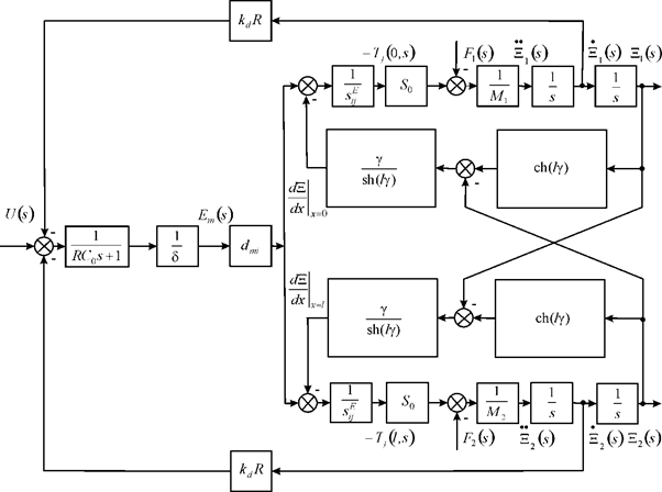
At voltage control on Figure 2 the transform of the voltage for two feedbacks is obtained in the form

Figure 2 Structural scheme piezoengine.
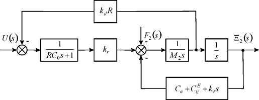
The structural scheme of piezoengine on Figure 3 is obtained at voltage control of piezoengine with elastic inertial load and first fixed end.

Figure 3 Structural scheme piezoengine with elastic inertial load.
At voltage control of piezoengine with elastic inertial load and fixed first end on Figure 3 is determined
,
,
here
- the reverse coefficient of piezoengine at voltage control.
At
the transfer function of PZT engine is founded
,
,
At PZT engine
its time constant is obtained
with 10% error. At
its transfer coefficient is determined
with 10% error.
An electroelastic engine micro and nano displacement is used for applied bionics and biomechanics in system of adaptive optics and scanning microscopy. The structural scheme of electroelastic engine for micro and nano displacement is determined by method mathematical physics. For an electroelastic engine its displacement matrix is constracted. The schemes piezoengines at the voltage control are obtained with the feedbacks. The structural scheme of piezoengine for applied bionics and biomechanics are constructed from equations of piezoeffects for the longitudinal, transverse and shift displacements and decision the ordinary differential equation piezoengine.
We have the general structural scheme, the transfer functions in matrix form of electroelastic engine micro and nano displacement from the solution this ordinary differential equation and the equation of electroelastic effect. The piezoengine at the transverse piezoeffect has greater range its displacement then the piezoengine at the longitudinal piezoeffect.
The general electroelastic engine micro and nano displacement are obtained for applied bionics and biomechanics. The systems of equations are determined for the structural model of electroelastic engine for applied bionics and biomechanics. The structural scheme of electroelastic engine and its transfer functions in matrix form are determined. The displacement matrix of electroelastic engine is obtained. At voltage control of piezoengine with elastic inertial load and fixed first end the structural scheme is determined with feedbacks. The structural scheme of PZT engine is determined. The structural model and scheme of electroelastic engine for micro and nano displacement are constructed. The matrix of the deformations of electroelastic engine is obtained. The parameters of PZT engine are determined at voltage control with elastic inertial load and fixed first end for applied bionics and biomechanics.
The author declares that there is no conflict of interest.


