The nano piezoengine based on the inverse piezoeffect is used for applied biomechanics and biosciences, nanomedicine, nanobiology, microsurgery. The nano piezoengine is provided for applied biomechanics and biosciences in scanning probe microscopy, interferometers and adaptive optics, actively dampen vibrations, deform mirrors and the work with the genes.1–6
For calculation nano systems the structural model and scheme of the nano piezoengine are used, which reflect the conversion of electrical energy into mechanical energy of the control object.6–19
Structural model
For calculation the nano piezoengine on Figure 1 is determined the inverse piezoeffect.1–49
here
are piezomodule, elastic compliance, strength electric field, strength mechanical field, relative deformation.
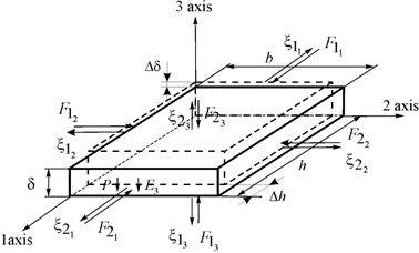
Figure 1 Nano piezoengine.
For the nano piezoengine the differential equation is evaluated4–56
here
are the transform of deformation, the coordinate, the parameter of transform, the factor of propagation.
For the longitudinal piezoengine at
the deformation
, at
are calculated.
Its solution is written4–36
For the nano longitudinal piezoengine in Figure 1 its relative displacement on 3 axes1–29 has the form
The system for the nano longitudinal piezoengine is obtained11–31 for
The structural model is evaluated for applied biomechanics and biosciences
here
- the transformations of displacements,
- the area.
For the nano transverse piezoengine the expression of the transverse inverse piezoeffect1–29
The system for the nano transverse piezoengine is determined for
and
The structural model of the nano transverse piezoengine is calculated
For the nano shift piezoengine the expression of the shift inverse piezo effect1–29
The system for the shift piezoengine is written at
and
The structural model is calculated
At
and
for
the system in general is obtained
The structural model and scheme of the nano piezoengine on Figure 2 are evaluated
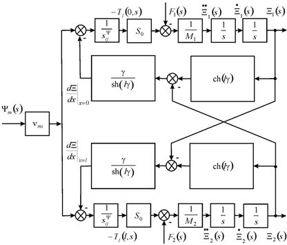
Figure 2 In general scheme of nano piezoengine.
The displacements matrix is calculated
The static longitudinal displacements are evaluated
For
=
,
= 25 V,
= 1 kg,
= 4 kg the static displacements
= 8 nm,
= 2 nm and
= 10 nm are evaluated at error 10%.
The equation of the direct piezo effect is used1–29
here
- the permittivity, the electric induction and the direct coefficient. The transform the voltage of feedback for the nano piezoengine on Figure 3 is calculated
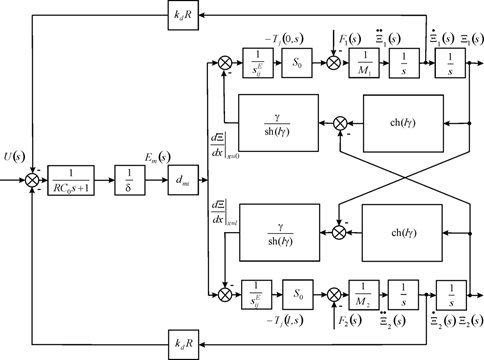
Figure 3 Scheme of nano piezoengine with back electromotive force.
For the nano piezoengine its static deformation is obtained.
For voltage control
For current control
here
- the sectional area of capacitor, the capacitance, and the coefficient of electromechanical coupling.
For current control of the nano piezoengine
The mechanical characteristic of the nano piezoengine is obtained
The expression of the mechanical characteristic of the nano transverse piezoengine is calculated
At
=
,
= 0.5∙105 V/m, h = 2.5∙10-2 m,
= 1.5∙10-5 m2,
= 15∙10-12 m2/N the parameters
= 250 nm,
= 10 N are obtained on Figure 4 at error 10%.
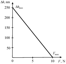
Figure 4 Mechanical characteristic of nano transverse piezoengine.
The deformation piezoengine at elastic load is obtained
The control characteristic of the nano piezoengine is determined
here
the coefficients change of elastic compliance.
For the nano piezoengine its reverse and direct coefficients are calculated
By using the equation of load the scheme of the nano piezoengine with one fixed face on Figure 5 is calculated.
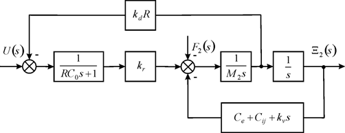
Figure 5 Scheme of nano piezoengine with one fixed face.
The expression on voltage for Figure 4 is calculated
here
- the coefficient of damping.
For the nano transverse piezoengine for
the expression on voltage is determined
For
= 2 kg,
=
,
=
the parameters
= 0.33×10⁻³ s,
=
are evaluated on Figure 6 at error 10%.
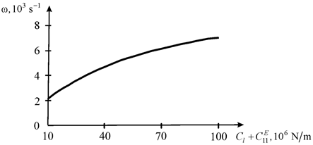
Figure 6 Bandwidth of nano transverse piezoengine.
The static displacement
For
=
,
= 24,
= 0.1 the parameter
= 4.4 nm/V is evaluated at error 10%.


