An electromagnetoelastic engine is used for the nano alignment in adaptive optics, in tunnel microscopy and interferometers in nanomedicine and applied bionics, in the ring quantum generators, in the dampen mechanical vibrations, in the penetration in a cells and the genes.1–15 For construction structural model of an electromagnetoelastic engine the methods mathematical physics are applied. In an electromagnetoelastic engines as active elements are used piezo or magnetostricton engenes. In difference from Cady and Mason equivalent electric schemes8–10 for calculations the deformations an electromagnetoelastic engine its structural scheme and its transfer functions are applied.14–23
Structural model and scheme
Methods mathematical physics with decision the equation of the reverse electromagnetoelastic effect and the differential equation of an electromagnetoelastic engine at boundary conditions are used for calculation structural model of an engine and its structural scheme. An engine works on basis of the reverse electromagnetoelastic effect in the form3–59
where
,
,
,
,
are the relative deformation, control parameter in the form strength electric field, induction and strength magnetic field, strength mechanical field, elastic compliance at
the electromagnetoelastic module in the form piezo module, piezo const and magnitostriction const, i, j, m are indexes.
The differential equation3–59 of an electromagnetoelastic engine has form
,
here
, s, ,
,
,
,
are the Laplace transform of the deformation, the parameter transform, the coordinate, the propagation factor, the speed of sound at
coefficient wave attenuation.
For an electromagnetoelastic engine we have its decision at
the trasform first deformation
and at
the trasform second deformation
.
The decision this differential equation has the form
where
,
are the transforms of the deformations.
Then we have the system strength mechanical field for two faces an electromagnitoelastic engine in the form
,
where
the length of an electromagnitoelastic engine.
The general structural model and structural scheme on Figure 1 of an electromagnitoelastic engine are determined
,
where
,
,
The structural model and the structural scheme of an electromagnetoelastic engine on Figure 1 are used for the design of a precise control system for nano and micro bionics.
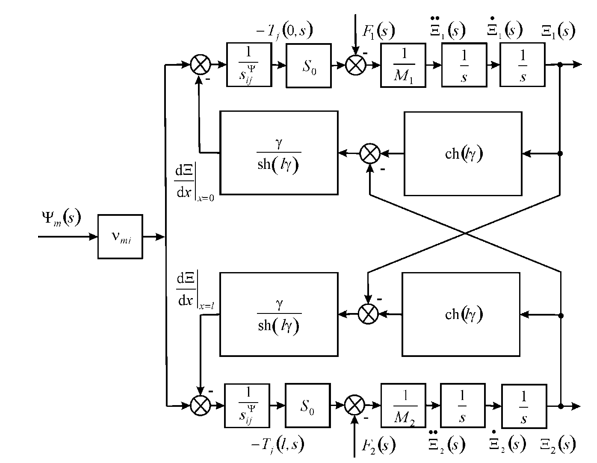
Figure 1 Structural scheme an electromagnetoelastic engine.
The matrix of the deformations is written
where
,
,
,
The structural model and the structural scheme of an electromagnetoelastic engine are constructed at two mass load. In general the matrix of the deformations of an electromagnetoelastic engine are obtained for the constructions of the engine at two mass load in the step engine.
For
,
at inertial load the static displacement the faces of an electromagnetoelastic engine
and
we have the form
,
where
is the mass of the electrmagnetoelastic engine,
are the load masses.
For the static displacements of the longitudinal piezo engine for
and
we have equations in the form
,
where
is the thickness of the piezo engine. For the PZT longitudinal piezo engine
= 4×10⁻¹⁰ m/V,
= 100 V,
= 1 kg,
= 4 kg we have the module of displacements the faces
= 32 nm,
= 8 nm and summa module of displacements
= 40 nm at error 10%.
For the static displacements of the transverse piezo engine for
and
we have equations in the form
,
For the PZT transverse piezo engine
= 2.5×10⁻¹⁰ m/V,
= 20,
= 100 V,
= 1 kg,
= 4 kg we have the module of displacements the faces
= 400 nm,
= 100 nm and summa modules of displacements
= 500 nm at error 10%.
For
,
and the control voltage for the resistance
the transfer function on voltage for the transverse piezo engine is obtained in the form
,
where
is the Laplace transform of the voltage, is the time constant,
is the damping coefficient of the transverse piezo engine,
is the load rigidity,
is the transverse piezo engine rigidity at
.
Then the transfer function on voltage for
,
for the transverse piezo engine at one the fixed face the transfer expression is obtained
,
,
For
= 4 kg,
= 0.2×10⁷ N/m,
= 1.4×10⁷ N/m we have
= 0.5×10⁻³ s,
= 2×10³ s-1 at error 10%.
The static transverse deformation has the form
For
= 2.5x10⁻¹⁰ m/V,
= 20,
= 0.14 the coefficient is determined
= 4.4 nm/V at error 10%.
The parameters of the piezo engine with one the its fixed face are determined for nano and micro bionics. The parameters PZT transverse engine are found.