Centrifugal torques acting on a spinning sphere
The rotating center mass and mass elements generate several inertial forces acting on the spinning sphere. The inertial torques are acting simultaneously on the spinning sphere with a uniform circular motion.1–5 This section considers the action of the inertial torques on the solid and hollow spheres where mass elements are distributed on the spherical surfaces. The rotation of mass elements generates the centrifugal forces acting strictly perpendicular to the axis
and
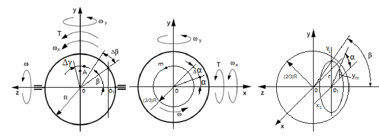
of the spinning sphere. The analytical approach for the modeling of the action of the centrifugal forces of the spinning sphere is the same as for the spinning disc represented in Chapter 3 of the gyroscope theory.19 The rotating mass elements of the sphere are located on the spherical surface of the 2/3 radius for the solid sphere and the middle radius for the hollow sphere. The analysis of the acting inertial forces generated by the mass element of the sphere is considered on the arbitrary planes that parallel to the plane of the maximal diameter of the sphere (Figure 1). The arbitrary circle plane of the sphere is the same as the plane
of the thin disc represented in.19 The plane of the mass elements generates the change in the vector components
, whose directions are parallel to the spinning sphere axle
. The integrated product of components for the vector change in the centrifugal forces
and their variable radius of location relative to axis
and
generate the resistance torque
and precession torque
. acting about axes
and
, respectively, whose expressions are identical.19

Figure 1 Schematic of the spinning sphere, its motions, and acting external torque.
The mass element m is disposed on the radius
of the sphere, where
indicates the solid
and hollow spheres
for the solid sphere and
for the hollow sphere). The sphere rotates in a uniform circular motion with a constant angular velocity ω in the counter-clockwise direction and generates the plane of the centrifugal forces
acting perpendicular to axis
. The centrifugal forces
represent the distributed load where the sphere’s mass elements are located. The inclination of the spinning sphere on the minor angle Δγ generates the change in the vector’s components
, whose directions are parallel to the sphere axle
. The integrated product of the vector change in the centrifugal forces
and their variable radius r about axis
generates the resistance torque
acting opposite to the external torque T.
The resistance torque
of the centrifugal force
is expressed by the following:
(1)
where ym = Risinβsinα is the normal component of r to axis
other components are as specified above.
The component of the centrifugal force
for arbitrarily chosen plane is represented by the following equation:
(2)
where
is the centrifugal force of the mass element m;,
, M is the mass of the sphere;
is the spherical angle;
is the spherical angle of the mass element; the radius r of the mass element rotation at the plane
is
, where
is the radius of the solid sphere;
is the radius of the hollow sphere; ω is the constant angular velocity of the sphere; α is the angle of the mass element’s location on the plane that parallel to plane
is the angle of the mass element’s location on the plane
is the angle of turn for the sphere’s plane around axis
for the small values of the angle)
Substituting the defined parameters into Eq. (1) yields the following:
-for the solid sphere
(3)
-for the hollow sphere
(4)
where all components are as specified above.
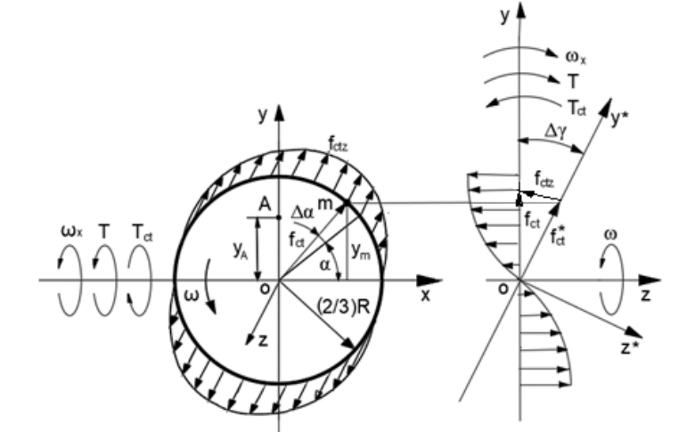
The change in the vectors of the centrifugal forces
on the angle
presents the vectors
which act around axis
in Figure 2.

Figure 2 Schematic of acting centrifugal forces and torques on the cross-section of the sphere about the axis ox.
The resultant torque is the product of the integrated centrifugal forces
and the centroid
(point A, Figure 2). The centroid is defined by the following expression:7,8
-for the solid sphere
(5)
-for the hollow sphere
(6)
where the components
,
are accepted at this stage of computing as a constant for Eqs. (5) and (6), respectively.
Substituting defined parameters
into Eqs. (3) and (4), where
,
,
,
and represented by the integral forms: and expressed by the integral forms with the limit for the hemisphere, the following equations emerge:
-for the solid sphere
(7)
-for the hollow sphere
(8)
Solving of integral Eqs. (7) and (8) yield the following:
-for the solid sphere
that gave rise to the following
(9)
-for the hollow sphere
that gave rise to the following
(10)
where the change of the limits is taken for a quarter of the sphere.
The angle γ is variable and depends on the angular velocity
of the sphere about axis ox.
The rate of change in the torque
per time is expressed by the differential equation
-for the solid sphere
(11)
-for the hollow sphere
(12)
where
is the time taken relative to the angular velocity of the spinning sphere and other parameters are as specified above.
The differential of time and the angle is:
, the expression
is the angular velocity of the sphere’s precession around axis ox. Substituting the defined components into Eqs. (11) and (12), separation of variables, presentation by the integral forms with defined limits, and solutions yield the following:
-for the solid sphere
,
,
(13)
-for the hollow sphere
,
,
(14)
The torque acts on the upper and lower and left and right sides of the sphere then the total resistance torque
of Eq. (13) and (14) is increased four times
-for the solid sphere
(15)
-for the hollow sphere
(16)
where
and
is the sphere mass moment of inertia for solid and hollow spheres respectively, other parameters are as specified above. The sign (±) is (+) for the precession torque whose direction is counter-clockwise about axis oy and (-) for the resistance torque whose direction is clockwise about the axis ox.
The expression for the precession torque generated by the centrifugal forces of the mass element is the same as for the resistance torque of the sphere considered above. The precession torque of the centrifugal forces acts around the axis oy as illustrated in Figure 2.
Coriolis torque and the change in the angular momentum acting on a spinning sphere
The modeling of the action of Coriolis forces generated by the mass elements of the spinning sphere is almost the same as for the centrifugal forces.19 Coriolis forces are generated by the rotating mass elements located on parallel planes of the sphere. The resistance torque
of Coriolis force of the mass elements
of the spinning sphere is expressed by the following:
(17)
where
is the distance to the mass element’s location along with axes oz and ox; other components are represented in Eq. (2).
The expression for
is represented by the following:
(18)
where
is Coriolis acceleration of the mass element along with axis oz;
is the change in the tangential velocity V of the mass element;
for the small-angle; other components are as specified above.
Substituting defined parameters into the expression of Coriolis force
(Eq. (17)) brings the following equations:
-for the solid sphere
(19)
-for the hollow sphere
(20)
Substituting defined parameters into (Eq. 17) yields the following equations:
-for the solid sphere
(21)
for the hollow sphere
(22)
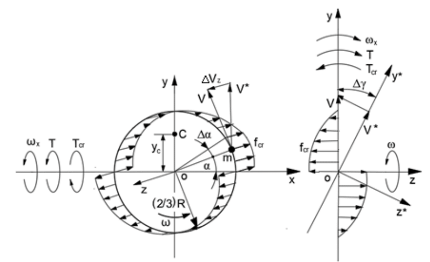
The change in the tangential velocity V of the mass elements of the cross-section of the sphere rotating about the axis ox presents the Coriolis acceleration
(Figure 3).

Figure 3 Schematic of the acting Coriolis forces, torques, and motions of the spinning sphere.
The location of the resultant force is the centroid of the area under the Coriolis force curve calculated by Eq. (5) for the centroid A. The centroid point C is defined for the resultant Coriolis force acting around the axis ox.
-for the solid sphere
(23)
-for the hollow sphere
(24)
where the components
and
is accepted as constant and the expression
The expressions of yC (Eqs. (23) and (24)) are substituted into Eqs. (21) and (22) respectively where
,
,
, and represented by the integral forms:
-for the solid sphere:
(25)
-for the hollow sphere:
(26)
where the limits of integration for the trigonometric expressions are taken for the hemisphere.
Solving of integrals Eq. (25) and (26) yields the following:
- for the solid sphere
that gave rise to the following
(27)
-for the hollow sphere
that gave rise to the following
(28)
The change of the limits at Eqs. (27) and (28) are taken for the quarter hemisphere.
Coriolis forces act on the upper and lower and left and right sides of the quarter hemisphere, and then the total resistance torque
is obtained when the result of Eqs. (27) and (28) is increased four times:
- for the solid sphere
(29)
-for the hollow sphere
(30)
where
and
7,8 is the sphere mass moment of inertia for solid and hollow spheres, respectively, other parameters are as specified above, and the sign (-) means the action of the torque in the clockwise direction.
The inertial torque of the change in the angular momentum is well-known in publications and presented by the following expression:
(31)
The analysis of Eqs. (17) and (31) show the resistance torques generated by centrifugal and Coriolis forces of the spinning sphere’s mass elements showing their summary action is opposite to the external torque. The precession torques are the sum of torques generated by the centrifugal inertial torque and the change in the angular momentum. The total resistance
and precession torque
have represented a sum of these torques whose equations are as follows:
(32)
(33)
-for the hollow sphere
(34)
(35)
where all components are as specified above
Attributes of the inertial torques acting on the spinning sphere
The obtained expressions of the inertial torques generated by the rotating mass of the solid and hollow sphere give the ability to formulate the mathematical models for its motions and compute the gyroscopic effects. The centrifugal, common inertial, and Coriolis forces of the mass element, as well as the change in the angular momentum, generate the inertial torques. These torques contain the principal components that are the change in the angular momentum and coefficients which belong to the defined type of inertial forces. The several inertial torques generated by the one rotating mass present active physical components. The total initial precession torque acting about axis oy of the spinning sphere has represented a sum of the precession torques generated by the common inertial forces of the mass elements and the change in the angular momentum. The total initial resistance torque
acting around axis ox has represented a sum of the resistance torques generated by the centrifugal and Coriolis forces of the sphere’s mass elements. The mathematical models for internal torques acting on the spinning sphere are represented in Table 1.
|
Type of the torque generated by
|
Action
|
Equation for the spinning sphere
|
|
Solid
|
Hollow
|
|
Centrifugal forces (axis ox)
|
Resistance
|
|
|
|
Centrifugal forces (axis oy)
|
Precession
|
|
Coriolis forces
|
Resistance
|
|
|
|
Change in an angular momentum
|
Precession
|
|
Table 1 Equations of the internal torques acting on the spinning sphere
The parameters of Table 1 are J is the moment of inertia of the sphere; ω is the angular velocity of the sphere; is the angular velocity of the sphere about axis ox,.The equations used to calculate the gyroscopic effects in engineering are derived from the inertial torques acting on the spinning solid and hollow sphere.
New studies of the inertial torques have shown that their values depend on the form of the spinning objects, whose geometry can be original designs. The equality of inertial torques originating along each axis defines the dependency of the angular velocities of the spinning sphere around two axes. This principle is formulated by the equality of kinetic energies of the sphere rotation about two axes ([], Chapter 4, Section 4.1.2). The relationship between the angular velocities of a spinning sphere around the oy and ox axes is defined for both solid and hollow spheres..
-The solid sphere
(36)
Simplification of Eq. (36) yields the following ratio of the angular velocities of the spinning solid sphere:
(37)
For the hollow sphere
(38)
Simplification of Eq. (38) yields the following ratio of the angular velocities of the spinning hollow sphere:
(39)
The dependency of the spinning sphere's angular velocities is used to create mathematical models for its rotation around axes ox and oy
Working example
The sphere has a mass of 1.0 kg, a radius of 0.1 m, and spinning at 3000 rpm. An external torque acts on the sphere, which rotates with an angular velocity of 0.05 rpm. It is determined the value of the resistance and precession torques acting on the spinning sphere (Figure 1). Substituting the initial data into equations of Table 1 and transformation yields the following result (Table 2).
|
Torque generated by
|
Solid sphere
|
Hollow sphere
|
|
Centrifugal fore Tct
|
|
|
|
Coriolis forces Tcr
|
|
|
|
Change in the angular momentum Tam
|
|
|
Table 2 Substituting the initial data into equations
The method for deriving the mathematical models for the inertial torques has been demonstrated on the spinning sphere. This analytical approach opens new possibilities to solve engineering problems related to the gyroscopic effect and presents the physical principles behind the acting forces. The new mathematical models for the inertial torques generated by the spinning sphere bring new knowledge to the dynamic of rotating objects of engineering mechanics.


