Its transverse solution is written
here
,
;are the transforms its end displacements.
The system equations of the boundary conditions for the transverse piezoengine is determined
From the reverse piezoeffect of a piezoengine at the voltage control the Laplace transform of the force causes displacement is determined
here
is cross sectional area.
The transform of the force causes displacement for the transverse piezoengine at the voltage control is written
Then the reverse coefficient at the voltage control with
is determined in the form
The transverse reverse coefficient at the voltage control is obtained
Its transverse model is determined
For the longitudinal piezoengine its longitudinal solution of the differential equation is written
The system of the boundary conditions for the longitudinal piezoengine is obtained
The transform of the force causes displacement for the longitudinal piezo engine at the voltage control is written
The longitudinal reverse coefficient at the voltage control is obtained
Its longitudinal structural model is determined
From the differential equation of for the shift piezoengine its shift solution is written
The system of the boundary conditions for the shift piezoengine is obtained
The transform of the force causes displacement for the shift piezo engine at the voltage control is written
The shif reverse coefficient at the voltage control is obtained
Its structural shift model is determined
The equation of inverse piezo effect 3–41 is written in the general form
here
is control parameter at the voltage or current control.
At
and
for
the system of the boundary conditions for a piezoengine is obtained
The transform of the force causes displacement has the general form
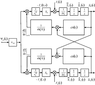
The general structural model and scheme are obtained on Figure 1

Figure 1 General scheme engine.
here
,
,
,
,
,
The general structural model and scheme of a piezoengine on Figure 1 are used to calculate systems in aeronautics and aerospace. The displacement matrix is written
here its functions
The settled longitudinal displacements at the voltage control are used
To the PZT piezoengine
= 4×10⁻¹⁰ m/V,
= 50 V,
= 0.5 kg,
= 2 kg we have displacements
= 20 nm,
= 16 nm,
= 4 nm with 10% error.
For the voltage control the equation of the direct piezo effect is written8–41
here i, m, k are the indexes,
is the permittivity. The direct coefficient
;for the engine at the voltage control is founded
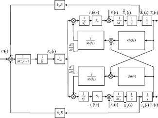
At the voltage control the transform of the voltage for the feedback on Figure 2 is obtained

Figure 2 Scheme engine with two feedbacks.
,
here the number
of the ends engine.
Let us consider the elastic compliance of a piezoengine. At voltage control its maximum parameters are written
At current control the maximum force is founded
here
,
are the sectional area of the capacitor, its capacitance.
Then at current control the parameters are written
here
is the coefficient of electromechanical coupling.
At current control of the parameters are founded
The elastic compliance
is written
, here
. Then
is the stiffness of the engine at voltage control,
is the stiffness at current control,
,
is a general stiffness of an engine.
The mechanical characteristic of a piezoengine 8–41
The adjustment characteristic
Then the mechanical characteristic is written
,
here
,
are the maximum of the displacement and the force. The transverse mechanical characteristic is founded
,
To the PZT piezoengine
= 2∙10-10 m/V,
= 0.25∙105 V/m,
= 2.5∙10-2 m,
= 1.5∙10-5 m2,
= 15∙10-12 m2/N the parameters are determined
= 125 nm and
= 5 N with 10% error.
The relative displacement at elastic load
,
The adjustment characteristic
The general elastic compliance
,
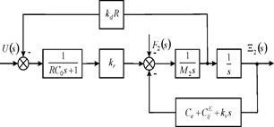
The scheme on Figure 3 we have at the voltage control the piezoengine with first fixed end and elastic-inertial load.

Figure 3 Scheme engine with one feedback.
The function at the voltage control with fixed first end and elastic-inertial load on second end for Figure 3 has the form
,
,
The function withis obtained
,
To the PZT piezoengine
= 4 kg,
= 0.1×10⁷ N/m,
= 1.5×10⁷ N/m the parameters are founded
= 0.5×10⁻³ s,
= 2×10³ s-1 with 10% error.
To
= 2∙10-10 m/V,
= 22,
= 0.1 the coefficient is determined
= 4 nm/V with 10% error.


