Research Article Volume 8 Issue 1
National Research University of Electronic Technology, Russia
Correspondence: Afonin SM, National Research University of Electronic Technology, MIET, 124498, Moscow, Russia
Received: December 19, 2023 | Published: February 8, 2024
Citation: Afonin SM. Structural scheme of piezoactuator for astrophysics. Phys Astron Int J. 2024;8(1):32‒36. DOI: 10.15406/paij.2024.08.00328
In the work is calculated of the piezoactuator for astrophysics. The structural scheme of the piezoactuator is determined for astrophysics. The matrix equation is constructed for the piezoactuator. The mechanical characteristic is determined. The parameters of the piezoactuator are obtained in nano control systems for astrophysics.
Keywords: Piezoactuator, Structural scheme, Astrophysics
The piezoactuator is used for astrophysics.1-43 In nanotechnology and precision machining the piezoactuator is widely used.17-19,58 The piezoactuator is applied for the nano alignment in adaptive optics and interferometers.4-59
The method mathematical physics is using for calculation the structural scheme of piezoactuator in nano control systems for astrophysics.
Structural scheme of piezoactuator
The structural scheme of the piezoactuator for astrophysics is calculated by the method mathematical physics by using the equations of the inverse and direct piezoeffects and the decision of the second order ordinary differential equation for the piezoactuator. From the structural model and scheme we have the matrix equation and the mechanical characteristic the nano piezoactuator, and its parameters in adaptive optics for astrophysics.
Let us construct of structural models of piezoactuators. The expression of the inverse piezoeffect.1-15
Si=dmiEm+sEijTjSi=dmiEm+sEijTj
here SiSi , dmidmi , EmEm , sEijsEij , TjTj , are the relative displacement, piezomodule, strength electric field, elastic compliance, strength mechanical field.
The expression of the longitudinal inverse piezoeffect has the form.1-15
S3=d33E3+sE33T3S3=d33E3+sE33T3
The second order ordinary differential equation of the piezoactuator is used.4-54
d2Ξ(x,s)dx2−γ2Ξ(x,s)=0d2Ξ(x,s)dx2−γ2Ξ(x,s)=0
here Ξ(x,s)Ξ(x,s) , s, x, γ are the Laplace transform of the displacement, the parameter, the coordinate, the coefficient of propagation. For the longitudinal piezoactuator we have at x=0x=0 the deformation Ξ(0,s)=Ξ1(s)Ξ(0,s)=Ξ1(s) and at x=δx=δ Ξ(δ,s)=Ξ2(s)Ξ(δ,s)=Ξ2(s) . The decision is calculated.
Ξ(x,s)={Ξ1(s)sh[(δ−x)γ]+Ξ2(s)sh(xγ)}/sh(δγ)Ξ(x,s)={Ξ1(s)sh[(δ−x)γ]+Ξ2(s)sh(xγ)}/sh(δγ)
From the expression of the longitudinal inverse piezoeffect and and two boundary conditions we have the set of equations.4-32
T3(0,s)=1sE33dΞ(x,s)dx|x=0−d33sE33E3(s)T3(0,s)=1sE33dΞ(x,s)dx∣∣x=0−d33sE33E3(s)
T3(δ,s)=1sE33dΞ(x,s)dx|x=δ−d33sE33E3(s)T3(δ,s)=1sE33dΞ(x,s)dx∣∣x=δ−d33sE33E3(s)
After using the decision of the differential equation of the we have the structural model of the longitudinal piezoactuator.
Ξ1(s)=(M1s2)−1{−F1(s)+(χE33)−1×[d33E3(s)−[γ/sh(δγ)] ×[ch(δγ)Ξ1(s)−Ξ2(s)]]}Ξ1(s)=(M1s2)−1⎧⎪ ⎪⎨⎪ ⎪⎩−F1(s)+(χE33)−1×[d33E3(s)−[γ/sh(δγ)]×[ch(δγ)Ξ1(s)−Ξ2(s)]]⎫⎪ ⎪⎬⎪ ⎪⎭
Ξ2(s)=(M2s2)−1{−F2(s)+(χE33)−1×[d33E3(s)−[γ/sh(δγ)]×[ch(δγ)Ξ2(s)−Ξ1(s)]]}Ξ2(s)=(M2s2)−1⎧⎪ ⎪⎨⎪ ⎪⎩−F2(s)+(χE33)−1×[d33E3(s)−[γ/sh(δγ)]×[ch(δγ)Ξ2(s)−Ξ1(s)]]⎫⎪ ⎪⎬⎪ ⎪⎭
χE33=sE33/S0χE33=sE33/S0
here Ξ1(s)Ξ1(s) , Ξ2(s)Ξ2(s) are the Laplace transforms of the displacements, S0S0 is the area.
The expression of the transverse inverse inverse piezoeffect has the form1-15
S1=d31E3+sE11T1S1=d31E3+sE11T1
The decision of the differential equation is written.
Ξ(x,s)={Ξ1(s)sh[(h−x)γ]+Ξ2(s)sh(xγ)}/sh(hγ)Ξ(x,s)={Ξ1(s)sh[(h−x)γ]+Ξ2(s)sh(xγ)}/sh(hγ)
From the expression of the transverse inverse piezoeffect and two boundary conditions we have the set of equations.
T1(0,s)=1sE11dΞ(x,s)dx|x=0−d31sE11E3(s)T1(0,s)=1sE11dΞ(x,s)dx∣∣x=0−d31sE11E3(s)
T1(h,s)=1sE11dΞ(x,s)dx|x=h−d31sE11E3(s)T1(h,s)=1sE11dΞ(x,s)dx∣∣x=h−d31sE11E3(s)
By using the decision of the differential equation of the we have the structural model of the transverse piezoactuator.
Ξ1(s)=(M1s2)−1{−F1(s)+(χE11)−1×[d31E3(s)−[γ/sh(hγ)] ×[ch(hγ)Ξ1(s)−Ξ2(s)]]}Ξ1(s)=(M1s2)−1⎧⎪ ⎪⎨⎪ ⎪⎩−F1(s)+(χE11)−1×[d31E3(s)−[γ/sh(hγ)]×[ch(hγ)Ξ1(s)−Ξ2(s)]]⎫⎪ ⎪⎬⎪ ⎪⎭
Ξ2(s)=(M2s2)−1{−F2(s)+(χE11)−1×[d31E3(s)−[γ/sh(hγ)]×[ch(hγ)Ξ2(s)−Ξ1(s)]]}Ξ2(s)=(M2s2)−1⎧⎪ ⎪⎨⎪ ⎪⎩−F2(s)+(χE11)−1×[d31E3(s)−[γ/sh(hγ)]×[ch(hγ)Ξ2(s)−Ξ1(s)]]⎫⎪ ⎪⎬⎪ ⎪⎭
χE11=sE11/S0χE11=sE11/S0
The expression of the shift inverse inverse piezoeffect has the form.1-15
S5=d15E1+sE55T5S5=d15E1+sE55T5
The decision of the differential equation has the form.
Ξ(x,s)={Ξ1(s)sh[(b−x)γ]+Ξ2(s)sh(xγ)}/sh(bγ)Ξ(x,s)={Ξ1(s)sh[(b−x)γ]+Ξ2(s)sh(xγ)}/sh(bγ)
From the expression of the shift inverse piezoeffect and two boundary conditions we have the set of equations.
T5(0,s)=1sE55dΞ(x,s)dx|x=0−d15sE55E1(s)T5(0,s)=1sE55dΞ(x,s)dx∣∣x=0−d15sE55E1(s)
T5(b,s)=1sE55dΞ(x,s)dx|x=b−d15sE55E1(s)T5(b,s)=1sE55dΞ(x,s)dx∣∣x=b−d15sE55E1(s)
By using the decision of the differential equation we have the structural model of the shift piezoactuator.
Ξ1(s)=(M1s2)−1{−F1(s)+(χE55)−1×[d15E1(s)−[γ/sh(bγ)] ×[ch(bγ)Ξ1(s)−Ξ2(s)]]}Ξ1(s)=(M1s2)−1⎧⎪ ⎪⎨⎪ ⎪⎩−F1(s)+(χE55)−1×[d15E1(s)−[γ/sh(bγ)]×[ch(bγ)Ξ1(s)−Ξ2(s)]]⎫⎪ ⎪⎬⎪ ⎪⎭
Ξ2(s)=(M2s2)−1{−F2(s)+(χE55)−1×[d15E1(s)−[γ/sh(bγ)]×[ch(bγ)Ξ2(s)−Ξ1(s)]]}Ξ2(s)=(M2s2)−1⎧⎪ ⎪⎨⎪ ⎪⎩−F2(s)+(χE55)−1×[d15E1(s)−[γ/sh(bγ)]×[ch(bγ)Ξ2(s)−Ξ1(s)]]⎫⎪ ⎪⎬⎪ ⎪⎭
χE55=sE55/S0χE55=sE55/S0
At l={ δ, h, bl={δ,h,b the decision in general of the differential equation of the piezoactuator has the form.
Ξ(x,s)={Ξ1(s)sh[(l−x)γ]+Ξ2(s)sh(xγ)}/sh(lγ)Ξ(x,s)={Ξ1(s)sh[(l−x)γ]+Ξ2(s)sh(xγ)}/sh(lγ)
From the expression of the inverse piezoeffect and two boundary conditions we have the set of equations.
Tj(0,s)=1sΨijdΞ(x,s)dx|x=0−νmisΨijΨm(s)Tj(0,s)=1sΨijdΞ(x,s)dx∣∣x=0−νmisΨijΨm(s)
Tj(l,s)=1sΨijdΞ(x,s)dx|x=l−νmisΨijΨm(s)Tj(l,s)=1sΨijdΞ(x,s)dx∣∣x=l−νmisΨijΨm(s)
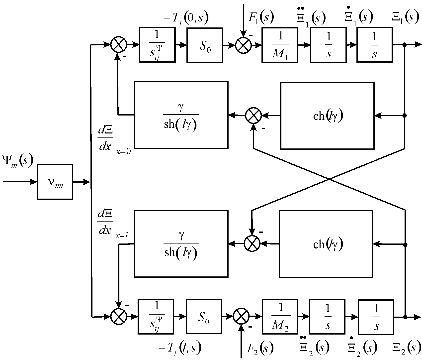
By using the decision in general of the second order ordinary differential equation the structural model in general of the nano piezoactuator is calculated on Figure 1.
Ξ1(s)=(M1s2)−1{−F1(s)+(χΨij)−1×[νmiΨm(s)−[γ/sh(lγ)]×[ch(lγ)Ξ1(s)−Ξ2(s)]]}Ξ1(s)=(M1s2)−1⎧⎪ ⎪ ⎪⎨⎪ ⎪ ⎪⎩−F1(s)+(χΨij)−1×[νmiΨm(s)−[γ/sh(lγ)]×[ch(lγ)Ξ1(s)−Ξ2(s)]]⎫⎪ ⎪ ⎪⎬⎪ ⎪ ⎪⎭
Ξ2(s)=(M2s2)−1{−F2(s)+(χΨij)−1×[νmiΨm(s)−[γ/sh(lγ)]×[ch(lγ)Ξ2(s)−Ξ1(s)]]}Ξ2(s)=(M2s2)−1⎧⎪ ⎪ ⎪⎨⎪ ⎪ ⎪⎩−F2(s)+(χΨij)−1×[νmiΨm(s)−[γ/sh(lγ)]×[ch(lγ)Ξ2(s)−Ξ1(s)]]⎫⎪ ⎪ ⎪⎬⎪ ⎪ ⎪⎭
χΨij=sΨij/S0χΨij=sΨij/S0
here
vmi={d33,d31,d15g33,g31,g15vmi={d33,d31,d15g33,g31,g15
Ψm=={E3,E1D3,D1Ψm=={E3,E1D3,D1
sΨij=={sE33,sE11,sE55sD33,sD11,sD55sΨij=={sE33,sE11,sE55sD33,sD11,sD55
γ={γE, γDγ={γE,γD
cΨ={ cE, cDcΨ={cE,cD
The matrix for the deformations of the piezoactuator from the structural model and scheme on Figure 1 is calculated.
(Ξ1(s)Ξ2(s))=(W11(s)W12(s)W13(s)W21(s)W22(s)W23(s)) (Ψm(s)F1(s)F2(s))(Ξ1(s)Ξ2(s))=(W11(s)W12(s)W13(s)W21(s)W22(s)W23(s))⎛⎜⎝Ψm(s)F1(s)F2(s)⎞⎟⎠
W11(s)=Ξ1(s)/Ψm(s)=νmi[M2χΨijs2+γth(lγ/2)]/AijW11(s)=Ξ1(s)/Ψm(s)=νmi[M2χΨijs2+γth(lγ/2)]/Aij
Aij=M1M2(χΨij)2s4+{(M1+M2)χΨij/[cΨth(lγ)]}s3++[(M1+M2)χΨijα/th(lγ)+1/(cΨ)2]s2+2αs/cΨ+α2Aij=M1M2(χΨij)2s4+{(M1+M2)χΨij/[cΨth(lγ)]}s3++[(M1+M2)χΨijα/th(lγ)+1/(cΨ)2]s2+2αs/cΨ+α2
W21(s)=Ξ2(s)/Ψm(s)=νmi[M1χΨijs2+γth(lγ/2)]/AijW21(s)=Ξ2(s)/Ψm(s)=νmi[M1χΨijs2+γth(lγ/2)]/Aij
W12(s)=Ξ1(s)/F1(s)=−χΨij[M2χΨijs2+γ/th(lγ)]/AijW12(s)=Ξ1(s)/F1(s)=−χΨij[M2χΨijs2+γ/th(lγ)]/Aij
W13(s)=Ξ1(s)/F2(s)==W22(s)=Ξ2(s)/F1(s)=[χΨijγ/sh(lγ)]/AijW13(s)=Ξ1(s)/F2(s)==W22(s)=Ξ2(s)/F1(s)=[χΨijγ/sh(lγ)]/Aij
W23(s)=Ξ2(s)/F2(s)=−χΨij[M1χΨijs2+γ/th(lγ)]/Aij
The longitudinal deformations are obtained.
ξ1=d33UM2/(M1+M2)
ξ2=d33UM1/(M1+M2)
For d33 = 4×10⁻¹⁰ m/V, U = 50 V, M1 = 1 kg, M2 = 4 kg we have ξ1 = 16 nm, ξ2 = 4 nm and ξ1+ξ2 = 20 nm with error 10%.
Let us evaluate the influence of the anti electromotive force on the deformation of the piezoactuator. The expression of the direct piezoeffect1-15 is used
Dm=dmiTi+εEmkEk
where Dm , εEmk are the electric induction and the permittivity,
The direct coefficient of the piezoactuator is written for calculation the voltage negative feedback from anti electromotive force.
kd=dmiS0δsEij
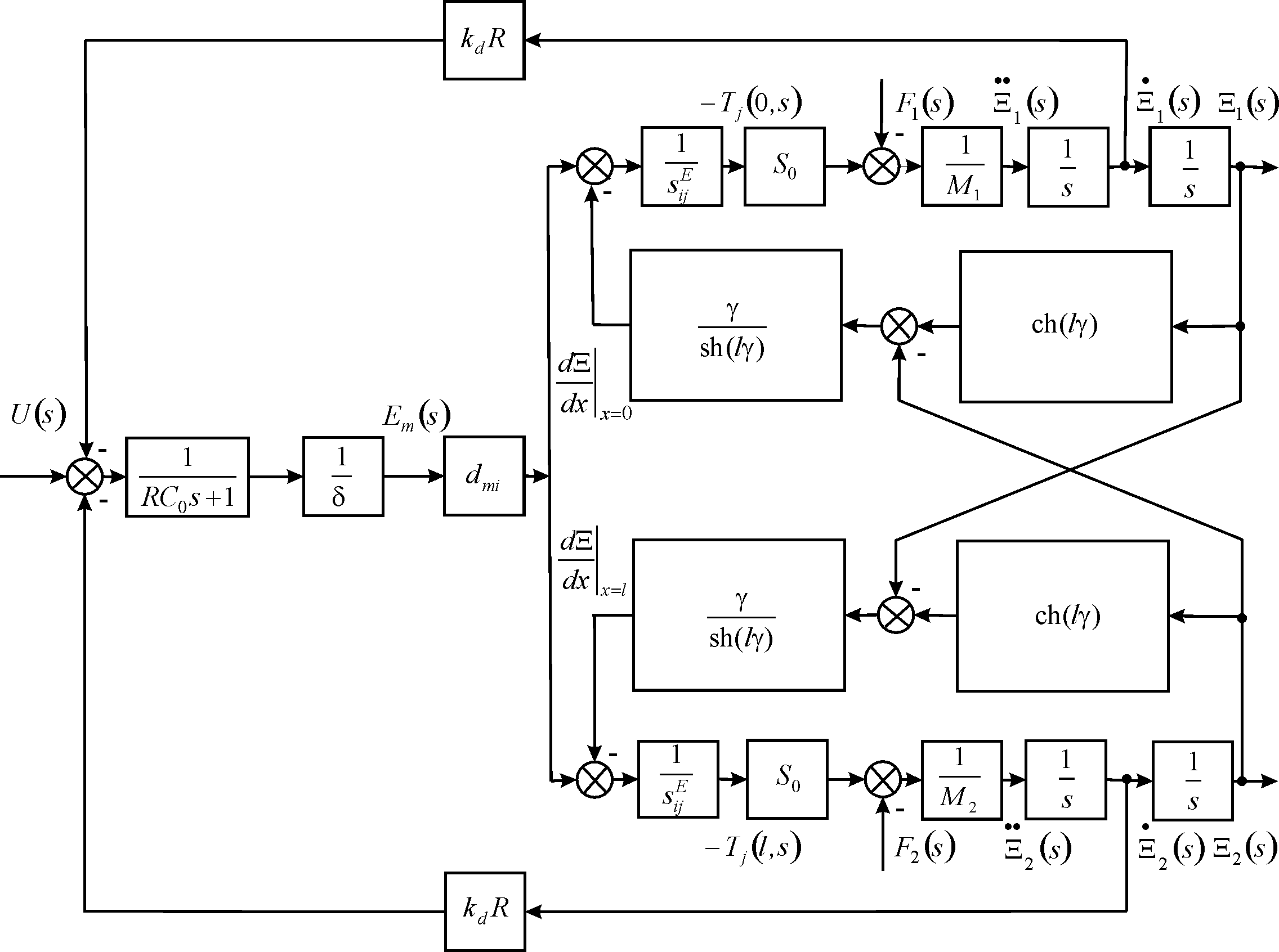
The expression of the voltage negative feedback from anti electromotive force on Figure 2 is used.
Ud(s)=dmiS0RδsEij•Ξn(s)=kdR•Ξn(s) , n=1, 2
The maximum the strength mechanical field and the force in the static working regime have the form at voltage control.
Tjmax=Emdmi/sEij
Fmax=EmdmiS0/sEij
The maximum force in the static working regime has the form at current control.
Fmax=UδdmiS0sEij+FmaxS0dmiSc1εTmkSc/δ1δdmiS0sEij
FmaxS0(1−d2miεTmksEij)sEij=Emdmi
Tjmax(1−k2mi)sEij=Emdmi
kmi=dmi/√sEijεTmk
here kmi is the coefficient of electromechanical coupling.
The expressions for the strength mechanical field and the maximum force in the static working regime we have at current control.
Tjmax=Emdmi/sDij
Fmax=EmdmiS0/sDij
sDij=(1−k2mi)sEij
The mechanical characteristic of the piezoactuator is determined in the static working regime.
Si(Tj)|Ψ=const=νmiΨm|Ψ=const+sΨijTj
The adjustment characteristic of the piezoactuator is calculated in the static working regime.
Si(Ψm)|T=const=νmiΨm+sΨijTj|T=const
The mechanical characteristic of the piezoactuator has the form.
Δl=Δlmax(1−F/Fmax)
Δlmax=νmiΨml
Fmax=Tj maxS0=νmiΨmS0/sΨij
The expression of the mechanical characteristic for the transverse piezoactuator is determined
Δh=Δhmax(1−F/Fmax)
Δhmax=d31E3h
Fmax=d31E3S0/sE11
At d31 = 2∙10-10 m/V, E3 = 0.25∙105 V/m, h = 2.5∙10-2 m, S0 = 1.5∙10-5 m2, sE11 = 15∙10-12 m2/N we have the parameters of the transverse piezoactuator Δhmax = 125 nm, Fmax = 5 N with error 10%
The deformation of the piezoactuator is obtained at voltage control and elastic load.
Δll=dmiEm−sEijS0F , F=CeΔl
The adjustment characteristic has the form.
Δl=dmilEm1+Ce/CEij
The coefficients of the piezoactuator in general are calculated for the structural scheme of the piezoactuator with negative feedback from anti electromotive force.
kd=kr=dmiS0δsij
sij=kssEij
(1−k2mi)≤ks≤1
At one fixed face and elastic-inertial load of the piezoactuator Figure 2 is transformed to Figure 3.
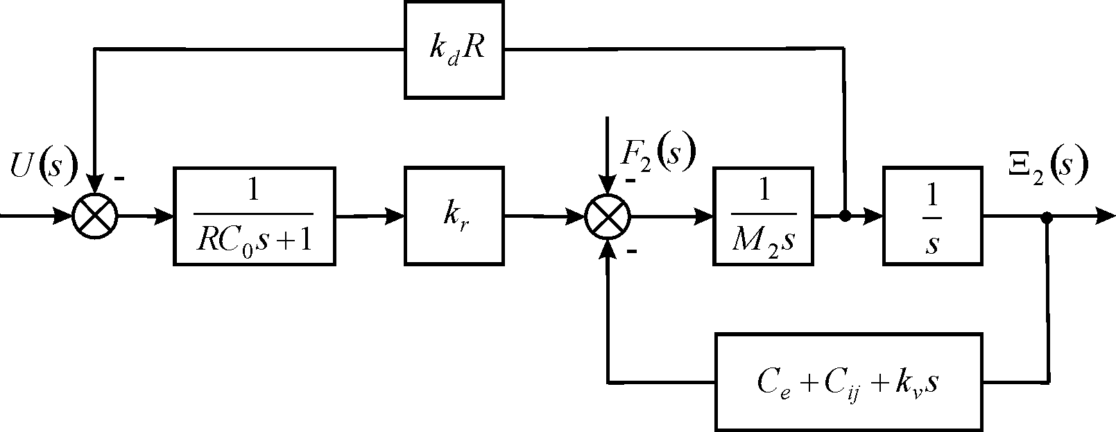
At R=0 we have the expressions for the transverse piezoactuator at voltage control.
W(s)=Ξ(s)U(s)=kU31 T2ts2+2Ttξts+1
kU31=d31(h/δ)/(1+Ce/CE11)
Tt=√M/(Ce+CE11) , ωt=1/Tt
At M = 4 kg, Ce = 0.1×10⁷ N/m, CE11 = 1.5×10⁷ N/m the parameters of the transverse piezoactuator are calculated Tt = 0.5×10⁻³ s, ωt = 2×10³ s-1 with error 10%.
The transverse deformation at voltage control has the form.
Δh=d31(h/δ)U1+Ce/CE11=kU31U
At d31 = 2∙10-10 m/V, h/δ = 22, Ce/CE11 = 0 we have the parameter of the transverse piezoactuator kU31 = 4 nm/V with error 10%.
The structural schemes of the piezoactuator for astrophysics are obtained by the method mathematical physics with using the equations of the inverse and direct piezoeffects and the decision of the second order ordinary differential equation of the piezoactuator. The matrix equation and the mechanical characteristic the nano piezoactuator are determined. The parameters of piezoactuator in adaptive optics for astrophysics are obtained.
The nano piezoactuator is calculated for nano control systems in adaptive optics for astrophysics. The structural schemes of the nano piezoactuator with electrical and mechanical parameters are calculated for astrophysics. In various working regimes the deformation of the nano piezoactuator is determined. The structural schemes of the piezoactuator are obtained. The matrix of the deformations of the piezoactuator is obtained. The parameters of the piezoactuator are determined for astrophysics.
None.
None.
©2024 Afonin. This is an open access article distributed under the terms of the, which permits unrestricted use, distribution, and build upon your work non-commercially.