Submit manuscript...
eISSN: 2576-4543

Physics & Astronomy International Journal

Research Article Volume 6 Issue 2

Design of non-zero dispersion shifted fiber with large effective area based on variational method

Faramarz E Seraji, Ali Emami, Niloofar Pakzad Afshar

Optical Communication Group, Communication Technology Dept, Iran Telecom Research Center, Iran

Correspondence: Faramarz E. Seraji, Optical Communication Group, Communication Technology Dept, Iran Telecom Research Center, Tehran, Iran

Received: November 18, 2021 | Published: April 21, 2022

Citation: Seraji FE, Emami A, Afshar NP. Design of non-zero dispersion shifted fiber with large effective area based on variational method. Phys Astron Int J. 2022;6(2):31-36. DOI: 10.15406/paij.2022.06.00247

Download PDF

Abstract

The determination of design parameters of large effective area fiber with segmented-core profile is presented by using simple variational method to obtain the effective area, mode field diameter, and dispersion of the fiber. The designed fiber has a large effective area of 171.1 μm2μm2 with mode field diameter, dispersion, and normalized cut off frequency of 9.7 μm,μm,  2.85 ps/nm.km, 2.491, respectively. The results have shown that the fiber with a bending radius of 35 mm, has a very low bending loss of 0.0053 dB/km. The calculated of parameters values of designed non-zero dispersion-shifted fiber (NZDSF) have shown that with a segmented-core profile of radius 3.5 μm,μm,  with a ring width of 0.2 μm,μm,  the core effective area AeffAeff increases from 152.3 μm2μm2  to 189 μm2,μm2,  which in practical point of view, is an achievement to reduce the nonlinearity effects in the NZDSF as transmission medium.

Keywords: NZDSF design, Large effective area fiber, Variational method

Introduction

To fulfill the rapid growth of bandwidth requirements in different fiber optic communication system applications, wavelength division multiplexing (WDM), dense wavelength division multiplexing (DWDM) systems, and fiber-to-the home (FTTH) networks have been introduced to employ newly designed optical fibers for better performance and reliabilities of high bit rate optical networks1 and long haul transmission optical systems.2-6 To increase the channel bit rate in a long haul transmission, the fiber nonlinearity effects should be avoided recommended by.7-10 Recent years, new fiber designs and further work have been introduced in high-capacity WDM transmission systems so as to minimize the nonlinearity effects and reduce down the signal distortion.11-18 In another work, a triangular segmented-core dispersion-shifted fibers was designed and fabricated with effective areas more than 80 µm2 which was later enhanced to about 90 µm2 by using a dual-ring profile.19

One of the popular fiber design, termed as Non-Zero Dispersion Shifted Fibers (NZDSF), operates in longer wavelength regions of 1530 to 1565 nm.20 A newer version of NZDSF is a large effective area fiber (LEAF), which provides greater effective area with a better performance compared with the previous NZDSF designs. It is shown that employing fibers with effective areas of 70 μm2 to 90 μm2 would increase the amplifier spacing considerably in comparison to systems using conventional 50 μm2 fibers.21

For the LEAF, different profiles are considered, e.g., Gaussian profile with ring,12 triangular–core profile with single ring and with dual ring,20 and depressed core triple-clad or quadruple-clad profile.22 The effective area, which could be obtained, ranges from 78 μm2 to 210 μm2.23 To minimize the dispersion penalty, the total dispersion should be small.24 Thus the concept of NZDSF was proposed.25-28 Typical dispersion value for NZDSFs is in the range of 3-8 ps/nm/km at 1550 nm with an effective area of about 50 μm2.29-32 NZDSFs have been widely deployed worldwide for high capacity WDM networks. Since the nonlinear effects are inversely proportional to the effective area of fiber, increasing the effective area will reduce further the nonlinear effects. To increase the effective area, different profiles designs with maximum large effective area of about 95 μm2 , 100 μm2, 100 μm2,150 μm2 were developed30,33 and fabricated34,35 respectively.

A design of depressed clad graded index NZDSF fiber with/without a central dip in the refractive index profile is reported, using the spot size optimization technique, by changing different fiber profile parameters to study the performance characteristics of the proposed NZDSF. By suitably adjusting these parameters, the obtained effective core area was about 80 μm2.36 In our previous attempt, we designed NZDSF fiber profile to reduce the positive dispersion and to enhance the negative dispersion. The obtained negative dispersion at 1550 nm wavelength were -528, -660, -710 ps/nm.km, from step-, triangular-, and exponential-index profiles, respectively.37

In later designs of NZDSFs, we have attempted to optimize theoretically the structural parameters of NZDSFs to improve the latency of optical networks such as internet of things (IoT), along with minimization of macro-bending losses of the designed fibers.38-41 In some particular cases the latencies were improved to 0.002 38 and 0.016.39

In this paper determination of design parameters for NZDSF of large effective area with a segmented-core profile with a raised ring is presented by using variational method based on Gaussian approximation for obtaining the effective area and other parameters of the designed fiber. We will show that with such a profile, if the parameters of the ring are determined appropriately, by using variational method, one can obtain enough large effective area for the LEAF fiber. We will show that among other parameters, the effective area is strongly dependent on the rate of evanescent field and the ring distance from the core. Our calculation have shown that the design values for the profile and variational parameters, such as values of the effective area, the mode field diameter (MFD), and the dispersion can be obtained with a simple mathematical calculations.

Index profile formulation

Let us consider a segmented-core profile with a raised ring located in the cladding in the vicinity of the core with a distance of p from the center, as shown in Figure 1.41 Mathematically, the profile of the fiber may be written as:

Figure 1 Segmented-core refractive index profile.

n1(R)={n21(12Δ1R),R1n23(12Δ2),1<Rpn23,p<Rp+qn23(12Δ2),p+q<Rn1(R)=⎪ ⎪ ⎪ ⎪ ⎪⎪ ⎪ ⎪ ⎪ ⎪n21(12Δ1R),R1n23(12Δ2),1<Rpn23,p<Rp+qn23(12Δ2),p+q<R   (1)

where R=ρ/aR=ρ/a  in which aa  and ρρ  are fiber core radius and the distance from the radius, respectively, and Δ1(n1n2)/n1,Δ1(n1n2)/n1,  Δ2(n3n2)/n3,Δ2(n3n2)/n3,  are the respective relative index heights of the core and the ring, and qq  n1,n1,  n2,n2,  n3n3  are width of the ring, refractive indices of core, cladding, and ring, respectively.

The fundamental mode field with a Gaussian function near and far from the fiber center is defined as:42,43

F(R)={exp(γR2/R20),RR0(R0/R)exp[(γ1/2)(2γ1/2)(R/R0)],RR0F(R)={exp(γR2/R20),RR0(R0/R)exp[(γ1/2)(2γ1/2)(R/R0)],RR0   (2)

where γγ  and R0R0  are constants for a given fiber and are found by minimizing the eigenvalue and obtaining a dimensionless parameters as:44

U2=V20RF2(R)g(R)dR+0R(dF/dR)2dR0RF2(R)dRU2=V20RF2(R)g(R)dR+0R(dF/dR)2dR0RF2(R)dR   (3)

where VV  and g(R)g(R) are the normalized frequency and profile function, respectively. From Figure 1, we define the function g(R)g(R) and its integral as follows:

g(R)={RR111<Rp0p<Rp+q1p+q<Rg(R)=⎪ ⎪ ⎪ ⎪⎪ ⎪ ⎪ ⎪RR111<Rp0p<Rp+q1p+q<R ,dg(R)dR={1R101<Rpδ(pR)p<Rp+qδ(p+qR)p+q<Rdg(R)dR=⎪ ⎪ ⎪ ⎪⎪ ⎪ ⎪ ⎪1R101<Rpδ(pR)p<Rp+qδ(p+qR)p+q<R   (4)

where δ(p)δ(p)  and δ(p+q)δ(p+q)  are delta Dirac functions at the beginning and end of the ring, respectively. In variational method, the value of UU in equ. (3) should be minimized, which is equivalent to equating the parameter WW  to zero as follows:42

W=KV20R2(dg(R)/dR)F2(R)dRW=KV20R2(dg(R)/dR)F2(R)dR   (5)

in which KK  is defined as:

K=20R(dF(R)/dR)2dRK=20R(dF(R)/dR)2dR   (6)

By applying the modified Gaussian approximation, KK can be written as:

K=1exp(2γ)+(2γ1/2)exp(2γ1)E1(4γ1)K=1exp(2γ)+(2γ1/2)exp(2γ1)E1(4γ1)   (7)

where E1(4γ1)E1(4γ1)  is an incomplete Gamma function given as:45

E1(4γ1)=4γ1exxdxE1(4γ1)=4γ1exxdx   (8)

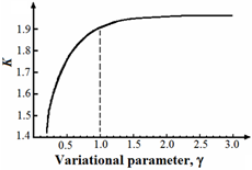
Figure 2 shows the variation of KK  in terms of variational parameter γ.γ.  

It is shown that for values of γγ  greater than unity, KK takes nearly constant values. On the other hand, equ. (2) shows that for a evanescent wave function in the cladding, we should have (2γ1/2)>0(2γ1/2)>0 , i.e.,γ>1/4.γ>1/4. Thus, from Figure 2 for every value of K,K, γ greater than unity, for almost constant value of K,K,  γ should satisfy the inequality 1/4<γ<1.1/4<γ<1.

Figure 2 The Variations of KK with respect to γγ .42

From F(R)F(R)  in equ. (2), we can determine the effective area Aeff,Aeff,  the MFDMFD , the normalized cutoff frequency Vc,Vc,  and the bending loss Rc,Rc,  by using the following equations:43,46

Aeff=2π[0F2(R)RdR]20F4(R)RdRAeff=2π[0F2(R)RdR]20F4(R)RdR ,MFD=22[0F2(R)RdR0(dF(R)/dR)2RdR]1/2MFD=220F2(R)RdR0(dF(R)/dR)2RdR1/2   (9)

Vc=2.405{20[1g(R)RdR]}1/2 ,αb=πκ2exp{23Rγ3β2}2γ3/2V2Rc{K1(γa)}2

where a  is the fiber radius, β is the propagation constant, V is the normalized frequency,κ and γ are constant related to β, and K1(γa)  represents the modified Bessel function.

For the chosen fiber profile, the variation of refractive index with respect to wavelength obtained by three-term Sellmeier formula, is determined by assuming 19.3% GeO2 for the core, 10.5% P2O5 for the ring indices, and a pure silica for the cladding region as follows:47

n2(λ)=1+b1λ2λ2a1+b2λ2λ2a2+b3λ2λ2a3   (10)

where a1, a2, a3  and b1, b2, b3 are Sellmeier coefficients, and λ denotes the wavelength. Then one can find β in terms of wavelength and thus calculate the total dispersion as:46

DT=λ2πc(2dβdλ+λd2βdλ2)   (11)

where c  is the velocity of light in vacuum and λ denotes the operating wavelength. In Table 1, values of the coefficient in Sellmeier's formula for pure and doped silica are presented and the corresponding variations of d2n/dλ20  are illustrated in Figure 3.48 It is shown that the doping slightly changes the ZMDW.48

Samples: Dopants

(Mole%)

A: Pure SiO2

B: GeO2 (19.3%)

C: P2O5 (10.5%)

a1

0.004679148

0.005847345

0.005202431

a2

0.01351206

0.01552717

0.01287730

a3

97.93400

97.93484

97.93401

b1

0.6961663

0.7347008

0.7058489

b2

0.4079426

0.4461191

0.4176021

b3

0.8974794

0.8081698

0.8952753

Table 1 Values of coefficient in Sellmeier's formula for pure and doped silica48
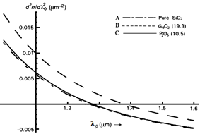
Figure 3 Variation of d2n/dλ20 for pure and doped silica. Curve indicators A to C: correspond various samples given in Table 1.

Determination of design parameters

We assume that the propagating wave is a modified Gaussian function. If R0  is used in the core region, then we can write from equs. (7) and (11) as:

W=KV2R00R2exp(2γR2/R20)dR1R0RR0exp[2γ1(4γ1)R/R0]dRpR0exp[2γ1(4γ1)R/R0](p+q)R0exp[2γ1(4γ1)R/R0]   (12)

Aeff=2πR20a21a2 MFD=2R02a1a3a3 ,Vc=2.405(1/3+q2+2pq)1/2   (13)

where a1, a2, and a3 are given as follows:

a1=1exp(2γ)4γ+exp(2γ)4γ1 , a2=1exp(4γ)8γ+exp(4γ2)E1(8γ2) ,

a3=12+1exp(2γ)2+(4γ1)exp(2γ1)4E1(4γ1)   (14)

in which E1(4γ1) and E1(8γ2) are incomplete Gamma functions and are evaluated by numerical integrations.

Numerical values and discussions

With reference to Figure 1, for every chosen values of p and q, the values of Vc should be greater than the calculated normalized frequency. The variations of Vc in terms of p and q are plotted in Figure 4, where the fiber radius is taken as 3.5μm.
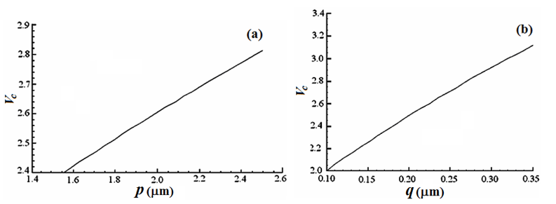
Figure 4 The variations of Vc as functions of (a) p with q=0.18μm and (b) q with p=0.18μm.

From equ. (13), the effective area and the values of MFD  are directly evaluated in terms of variational parameters and are illustrated in Figure 5 respectively. The effective area Aeff of the fiber strongly depends on γ values. Figure 5(a) indicates that for values of γ greater than 0.27, the Aeff is less than that of NZDSF. Figure 5(b) shows that the MFD  depends on monotonically decreasing values of γ parameter.
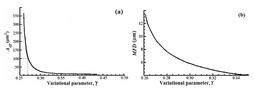
Figure 5 Dependences of (a) Aeff on γ and (b) MFD on γ

On the other hand, Aeff and MFD  increase when R0 increases, as shown in Figure 6. According to Fig. 6(a), variational parameter R0 is a criterion for pulse spread. On calculations, the values of R0>0.6  results in an MFD  of greater than 11 μm which outranges the value recommended by ITU-T standard. Therefore, based on curves of Figures 6(a) and 6(b), the values related to γ>0.27 and R0>0.6 are not considered further in our analysis.

Figure 6 The variations of (a) MFD and (b) Aeff as functions of R0.

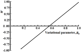
In equ. (12), it is shown that the variations of W directly depends on parameters such as R0, γ and the values of V, p, and q. Thus, these parameters should be chosen in such a way to satisfy W=0 in equ. (12).

Figure 7 illustrates the quantity W in terms of R0, where other parameters are taken as γ=0.2665, V=1.8, p=1.75μm,  and q=0.2μm.

Figure 7 Variation of W in terms of R0 with γ=0.2665, V=1.8, p=1.75μm, and q=0.2μm.

In Figure 8, the variations of Aeff  and MFD  with respect to p,  while q=0.2μm,  are plotted, respectively. These curves show that whenever p varies between 1.5μm to 2.0 μm, Aeff changes from 152.3 μm2  to 180μm2 and the MFD  increase from 9.19μm  to 11.1μm respectively.
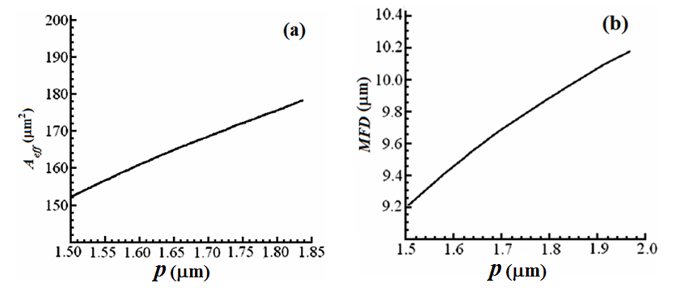
Figure 8 The variations of (a) Aeff and (b) MFD as functions of p with q=0.2μm.

Simultaneous consideration of the curves in Figure 8 reveals that although for a given value of p, Aeff  may be a maximum, but at the same time MFD may exceed its upper standard limit. Thus the value of p  should be chosen in such a way that both MFD and Aeff attain standard values.

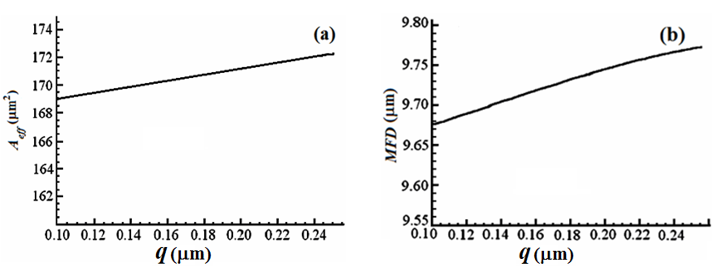
Similarly, in Figure 9, the curves are plotted versus q while p=1.75μm. With the same reasoning, a design trade-off should be observed in this case, as well. Evaluation of Figures 8 and 9 show that Aeff  and MFD are more sensitive to p than to q, i.e., the ring distance from the core center and the ring width, respectively. The sensitivity of MFD on p variations is more than that of Aeff.

Figure 9 The variations of (a) Aeff and (b) MFD as functions of q with p=1.75μm.

Another parameter which is affected by p and q variations, is the dispersion, as shown in Figure 10. In this case also, the variation of dispersion depends more on p  than on p variations.

Figure 10 Dispersion (a) versus p with q=0.2μm and (b) versus q with p=1.75μm.

Bending loss is another parameter which is directly influenced by the height of the ring. To achieve a largerAeff, design parameters would change in such a way that MFD and as a result, the bending loss increases, considerably. For this reason, a particular attention is needed to consider the bending loss as an important loss mechanism in the design procedure. In Figure 11, bending loss of the designed fiber is plotted versus the bending radius. The bending loss of 0.0053 dB/km is obtained against 35 mm bending radius by assuming q=0.2μm, p=1.75μm, γ=0.2665, a=3.5μm, and R0=0.565. The summary of the designed parameters compared with experimental values are given in Table 2.

Figure 11 Bending loss versus bending radius.
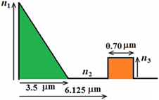
Figure 12 Designed segmented-core refractive index profile of NZDSF.

Parameters

Theoretical

Experimental

Δ1(n1n2)/n1  

0.01864

0.01490

Δ2(n3n2)/n3  

0.0046

0.0045

p value

6.125μm

6.100μms

q value

0.70μm

0.92μm

Vc  

2.491

2.980

λc  

1175 nm

1216 nm

Core radius

3.5μm

3.25μm

Table 2 Theoretical and experimental values of some parameters of the designed NZDSF

Conclusion

We have determined the design parameters of a fiber with a segmented-core profile, having a raised side ring in the vicinity of the core. We have shown that the modified Gaussian approximation function with a simple calculation procedure can lead to a reasonable precision in evaluating the design parameters. We have determined the characteristic parameters of the ring, i.e., height, distance of the ring from the core center, and the ring width, by the variational method and designed a single mode fiber of large effective area with low bending loss of  0.0035 dB/km.

Among the calculated parameters values, the ring distance from the core axis and the rate of decaying field in modified Gaussian function create more sensitivity in evaluation of designed fiber parameters.

The design calculations have shown that in a large effective area fiber with a segmented-core profile of radius 3.5μm by choosing a ring width of 0.2μm at distance varying from 1.5μm to 2.0μm the effective area Aeff changes from 152.3 μm2 to 189 μm2 and the MFD increases from 9.19μm to 11.1μm, respectively.

The height of the ring is determined by the refractive index of the material used for creating it. This parameter directly affects the dispersion, but the Aeff and the MFD  values are affected by parameters such as MFD p, q  (see Figure 1).

References

  1. Kazuo Hogari, Shigekatsu Tetsutani, Jian Zhou, et al. Optical‒Transmission Characteristics of Optical‒Fiber Cables and Installed Optical‒Fiber Cable Networks for WDM Systems. J Lightwave Technol. 2002;2(2):540‒545.
  2. Shinya Takaoka, Fumiyoshi Ohkubo, Kouichi Uchiyama, et al. Next Generation Non‒Zero Dispersion Shifted Optical Fiber PureMetro for DWDM & Full Spectrum CWDM Systems. SEI Tech. Rev. 2002;54:95‒98.
  3. Yoshinori Yamamoto, Masaaki Hirano. Next Generation Optical Transmission Fibers, IEEE Photon. Conf., Bellevue, Washington, USA. 2013;277‒278.
  4. Ming‒Jun Li, Daniel A Nolan. Optical Transmission Fiber Design Evolution. J. Lightwave Technol. 2009;26(9);1079‒1091.
  5. Louis‒Anne de Montmorillon, Gerard Kuyt, Pascale Nouchi, et al. Latest advances in optical fibers. C.R. Physique. 2008;9:1045‒1054.
  6. Kazunori Mukasa, Katsunori Imamura, Masanori Takahashi, et al. Development of novel fibers for telecoms application. Opt Fiber Technol. 2010;16;367‒377.
  7. ITU‒T Rec. G.655, Characteristics of a non‒zero dispersion‒shifted single‒mode optical fibre and cable, 11/2009.
  8. D Marcuse. Single‒channel operation in very long nonlinear fibers with optical amplifiers at zero dispersion. J Lightwave Technol. 1991;9(3);356‒361.
  9. S Arai, Y Akasaka, Y Suzuki, et al. Low nonlinear dispersion‒shifted fiber, Proc. Optical Fiber Commun. Conf. (OFC’ 97) Tech. Dig., Dallas, Texas, United States, Paper TuN1, 1997;65.
  10. Yoshinori Yamamoto, Masaaki Hirano, Takashi Sasaki. Low‒Loss and Low‒Nonlinearity Pure‒Silica‒Core Fiber for Large Capacity Transmission. SEI Tech Rev. 2013;76:63‒68.
  11. K Ohsono, T Nishio, Y Bing, et al. Hitachi Cable Rev. 2003;22:1‒5.
  12. Shizhuo Yina , Kun‒Wook Chung, Hongyu Liu, et al. A new design for non‒zero dispersion‒shifted fiber (NZ‒DSF) with a large effective area over 100 μm2 and low bending and splice loss. Opt. Commun. 2000;177(1‒6):225‒232.
  13. Wonkyoung Lee, W J Shin, H S Seo, et al. Study on the design of Non‒Zero Dispersion Shifted Fiber for ultra‒wide band WDM transmission. Proc. 27th Eur. Conf. on Opt. Commun. (ECOC'OI‒Amsterdam). 2001;392‒393.
  14. Masaharu Ohashi. History of Research and Development of Optical Fibers. IEICE Commun. Soc.‒Global Newslett. 2014;38(4):5‒7.
  15. Sivanantha Raja, S Selvendran, R Priya, et al. An optimized design for non‒zero dispersion shifted fiber with reduced nonlinear effects for future optical networks. Optica Applicata. 1994;24(4):503‒519.
  16. Sumitomo Fiber Specification, Non‒Zero Dispersion Shifted Single‒Mode Fiber. 1‒6.
  17. Pascale Nouchi, Louis‒Anne de Montmorillon, Pierre Sillard, et al. Optical fiber design for wavelength‒multiplexed transmission. C. R. Physique. 2003;4:29–39.
  18. Naomi Kumano, Kazunori Mukasa, Misao Sakano, et al. Development of a Non‒Zero Dispersion‒Shifted Fiber with Ultra‒low Dispersion Slope. Furukawa Rev. 2002;22.
  19. Yanming Liu, A Joe Antos, Mark A. Newhouse, Large effective area dispersion‒shifted fibers with dual‒ring index profiles, Opt. Fiber Commun. Conf. 1996, OSA Tech. Dig. Series (Opt. Soc. America)San Jose, Calif. USA, 1996, paper WK15.
  20. Y Liu. Single‒mode dispersion‒shifted fibers with large effective area for amplified systems, IOOC'95, Postdeadline paper PD‒19, Hong Kong, 1995;25‒30.
  21. O Audouin, J P Hamaide. Enhancement of amplifier spacing in long‒haul optical links through the use of large‒effective‒area transmission fiber, IEEE Photon. Technol Lett. 1995;7(11):1363‒1365.
  22. L G Cohen, W L Mammel, S J Jang. Low‒loss quadruple‒clad single‒mode lightguides with dispersion below 2 ps/km nm over the 1.28 μm‒1.65 μm wavelength range. Electron Lett. 1982;18(24):1023‒1024.
  23. Harold T Hattori, Ahmad Safaai‒Jazi. Fiber designs with significantly reduced nonlinearity for very long distance transmission. Appl Opt. 1998;37:3190‒3197.
  24. MJ Li, H Chen. Novel optical fibers for high‒capacity transmission system. Telecommun Sci. 2004;30(6):1–15.
  25. MA Newhouse, LJ Button, DQ Chowdhury, et al. Optical amplifiers and fibers for multiwavelength systems. Lasers and Electro‒Optics Soc. Annual Meeting Proc. 1995;2:44‒45.
  26. P Nouchi, P Sansonetti, S Landais, et al. Low‒loss single‒mode fiber with high nonlinear effective area. Proc OFC’95, 1995;260‒261.
  27. VL Da Silva, Y Liu, DQ Chowdhury, et al. Error free WDM transmission of 8×10 Gbit/s over km of LEAFTM optical fiber. 23rd Euro. Conf. Opt. Commun. 1997;1:154 –158.
  28. DW Peckham, AF Judy, RB Kummer. Reduced dispersion slope, non‒zero dispersion fiber. ECOC’98. 1998;1:139‒140.
  29. Y Liu. Dispersion shifted large‒effective‒area fiber for amplified high‒capacity long‒distance systems, OFC’97, Dallas, Texas. 1997;16‒21.
  30. P Nouchi. Maximum effective area for non‒zero dispersion‒shifted fiber. Opt. Fiber Commun. Conf. Exhibit. OFC '98, Tech Dig. 1998;303‒304.
  31. P Nouchi, P Sansonetti, J Von Wirth, et al. New dispersion shifted fiber with effective area larger than 90 μm2 ECOC '96. 1996;1:49‒52.
  32. Y Liu, G Berkey. Single‒mode dispersion‒shifted fibers with effective area over 100 μm2, ECOC’98. 1998;1:41‒42.
  33. Xiaoqiang Jiang, Ruichun Wang. Non‒zero dispersion‒shifted optical fiber with ultra‒large effective area and low dispersion slope for terabit communication system. Opt. Commun. 2004;236:69–74.
  34. Shoichiro Matsuo, Shoji Tanigawa, Kuniharu Himeno, et al. New medium‒dispersion fiber wlth large effective area and low dispersion slope. Opt. Fiber Commun Conf Exhibit. 2002;329‒330.
  35. K Mukasa, K Imamura, T Yagi. New type of positive medial dispersion fiber (P‒MDF150) with dispersion as 10 ps/nm.km and Aeff about 150 μm2. Opt Fiber Commun Conf. 2003;149‒150.
  36. Dipankar Ghosh, Debashri Ghosh, Mousumi Basu. Designing a graded index depressed clad non‒zero dispersion shifted optical fiber for wide band transmission system. Optik. 2008;119:63–68.
  37. Faramarz E Seraji, Razieh Kiaee. A Revisit of Refractive Index Profiles Design for Reduction of Positive Dispersion, Splice Loss, and Enhancement of Negative Dispersion in Optical Transmission Lines. Int J Opt App. 2014:4(2);62‒67.
  38. Faramarz E Seraji, Marzieh S Kiaee. Design optimization of NZDSF for low latency in IoT optical fiber network.  Phys Astron Int J. 2018;2(5)448‒450.
  39. Faramarz E Seraji, Shima Safari, Marzieh Sadat Kiaee, Design optimization of non‒zero dispersion shifted fiber for latency mitigation in optical fiber network. Phys Astron Int J. 2019;3(1):33‒36.
  40. Faramarz E Seraji, Shima Safari, Ali Emami, et al. Design of single‒mode optical fiber for low latency used in IoT optical transport networks. Phys Astron Int J. 2020:4(2):85‒91.
  41. T D Croft, JE Ritter, V A Bhagavatula. Low‒loss dispersion‒shifted single mode fiber manufactured by the OVD process. J Lightwave Technol. 1985;3(5):931‒934.
  42. Ankiewicz, GD Peng. Generalized Gaussian approximation for single‒mode fibers. J Lightwave Technol. 1992;10(1)22‒27.
  43. M Kato, K Kurokawa, Y Miyajima. A new design for dispersion shifted fiber with an effective core area larger than 100 μm2 and good bending characteristics. Opt. Fiber Commun. Conf., San Jose, Calif. USA, 22 1998, Tech . Dig., paper ThK1, ISBN: 1‒55752‒529‒3.
  44. Sharma S, I Hosain, A K Ghatak. The fundamental mode of graded‒index fibres: Simple and accurate variational methods. Opt. Quant. Electron. 1982;14:7‒15.
  45. YL Luke, Mathematical function and their approximations, Academic Press Inc., New York, 1975.
  46. W Snyder, J D. Love, Optical waveguide theory, Chapman & Hall, London, 1983.
  47. Ghatak, K Thyagarajan. Introduction to fiber optics, Cambridge University Press, New Delhi, 2002.
  48. Gowre S Mahapatra, P K Sahu. Dispersion characteristics of all‒glass crystal fibers, Optik: International Journal for Light and Electron Optics. 2013;124(18):3730‒3733.
Creative Commons Attribution License

©2022 Seraji, et al. This is an open access article distributed under the terms of the, which permits unrestricted use, distribution, and build upon your work non-commercially.