Review Article Volume 3 Issue 1
Design optimization of non-zero dispersion shifted fiber for latency mitigation in optical fiber network
Faramarz E Seraji,1 
Regret for the inconvenience: we are taking measures to prevent fraudulent form submissions by extractors and page crawlers. Please type the correct Captcha word to see email ID.

Shima Safari,2 Marzieh Sadat Kiaee1
1Optical Communication Group, Communication Technol Dept, Iran telecom Research Center, Iran
2Electrical and Computer Eng. Dept. North Branch, Islamic Azad University, Iran
Correspondence: Faramarz E Seraji, Faculty member Optical Communication Group, Department of Communication Technology, Iran Telecom Research Center, Tehran, Iran, Tel 9821 8497 7723, Fax 9821 8863 0047
Received: December 19, 2018 | Published: January 29, 2019
Citation: Seraji FE, Safari S, Kiaee MS. Design optimization of non-zero dispersion shifted fiber for latency mitigation in optical fiber network. Phys Astron Int J. 2019;3(1):33-36. DOI: 10.15406/paij.2019.03.00153
Download PDF
Abstract
Latency has an important role in new generation optical networks. There are a few ways to minimize latency in the optical networks. One way is to use silica in the core of optical fiber during the design of fabrication process. In this study, we have designed a non-zero dispersion shifted fibers (NZDSF) used as the transmission medium with minimal latency in an optical network. Using our optical fiber, the latency was improved by 0.016µs.
Keywords: design optimization, low-latency, NZDSF, optical fiber network
Introduction
Latency describes the time lapse between a transmitted and received signal. This parameter is crucial issue for high frequency traders associated with financial markets, In today’s marketing, high-frequency trading firms pay a premium for a latency advantage as just a few microseconds of delay in receiving trading information relative to a competitor can result in loss of deals with big financial impact.1,2
Latency in a link develops as a result of the delay caused by the following different factors:
- the signal processing in the electronics, the amplifiers, the dispersion compensating modules (if any) and
- the delay caused by optical propagations of the signal along the fiber length, the longer the fiber, the more latency.1,3
Besides the latency contributions from each of the above factors, it is apparent that the biggest contribution comes from the transmission fibers.4 As the transmission length exceeds 10km, the fiber becomes almost wholly responsible for the latency. The latency introduced by the fiber, is directly proportional to the group index of the fiber. So reducing the group index can lower the latency contribution from the transmission fiber.4
Latency is one of the important issues of new generation networks. To achieve lower latency, we need to use optical fiber with lower refractive index. So the core must be doped by using silica.
A typical pure silica core1 has a 0.4% lower group index relative to traditional fibers made of Ge-doped silica core [5]. This apparent insignificant latency would be noticeable in long haul propagation across the Atlantic Ocean. This time difference will be highly attractive to traders working between stock exchanges in two respective continents.
In order to optimize the latency of an optical network at higher distances, we should optimize the parameters of the optical fiber. During the light transmission, there are several parameters that affect on the quality of the received optical signals. One of these parameters is the nonlinear effects.6 To overcome nonlinearity, large effective area fibers (LEAF) have been employed.7 In the first generation, zero-dispersion shifted fibers (ZDSF) were used to achieve minimum loss and dispersion; but by increasing the number of signal wavelengths in DWDM networks, four-wave mixing (FWM) occurred which induces inter-channel crosstalk during the transmission of light.8,9
Besides ZDSFs, non-zero dispersion shifted fibers (NZDSF) have been designed which avoid the phase matching condition and reduce the effects of FWM in optical networks.1,4 By using NZDSF we may obtain a large effective area which minimizes the nonlinear effects;7 however, larger effective area makes fiber more sensitive to bending loss. So, choosing optimum parameters during the design of an optical fiber is very crucial for optical networks performances.
To start-up, we have studied the effects of other parameters while optimizing the optical fibers. During the design process, we have faced with many limitations. 1 Using optical fibers with very large effective area may cause a very high mode field diameter (MFD).10 In order to overcome this issue; the effective area must be limited. In a study, the upper limit of effective area in a single mode fiber was reported around 370
.11 In a study, an NZDSF with effective area of 95
, dispersion slop of 0.1ps/nm2km and bending loss of 0.005 dB has been designed. 12
An NZDSF with effective area of 102
, dispersion of 4ps/nm.km, dispersion slope of 0.06 ps/nm2km and bending loss of 0.0013dB/km at the wavelength 1550 nmwas designed and reported, where one dopant was employed in the core region of the optical fiber.13
In another study, these parameters were optimized by using three dopants to make different refractive index in the core; where the effective area was increased up to 120
and the bending loss was decreased down to
dB/km14. At wavelength 1550 nm, the dispersion, effective nonlinear refractive index and 1’st order PMD resulted in 5.78 ps/nm.km,
and
ps, respectively.
Besides all above parameters’ optimizations, one important parameter in the next generation communication systems is the signal latency between transmitting and receiving ends. As it is reported before, the typical group delay in a conventional single mode fiber is about
.15
Recently, we have designed an optical fiber network used in IoT in order to evaluate the quality of the received signals from 50 km of our designed NZDSF fiber. In this theoretical study, a non–zero dispersion shifted fiber (NZDSF) with a particular refractive index which had a minimum latency at 1352 nm was designed with an effective area of
and macrobending loss of
51dB/km. In comparison to a commercial NZDSF, the latency was improved by 16
To the best of our knowledge, considerable academic works have not been reported in the literatures on the present subject. In this paper, we have attempted to optimize design of an NZDSF fiber with minimal signal latency with an optimum effective area.
1Corning’s ultra-low-loss products (like SMF-28R ULL fiber and Vascade R EX2000 fiber).
Refractive index profile
As we know, the latency of light signal in a vacuum is
, so we must find the ways to minimize the signal latency of propagating light in an optical fiber medium for most signal velocity. To achieve this aim, we should optimize the refractive index profile of the transmission fiber for minimal group index so as to mitigate the fiber group index, thus results in higher group velocity of propagating signal. We have designed an NZDSF with a core of exponential profile assumed with Germanium dopant.
Adding Germanium or Fluorine will increase or reduce the refractive index of pure silica, respectively. The refractive index of
mole-percentage doped material can be defined as follows:16
(1)
where
is the refractive index of the host material and
is the refractive index of doped material with
mole percentage. Then the exponential function of the core is as follows:16
(2)
where
and
are the refractive indices at
and
, respectively, and
.
In order to calculate the latency of this fiber, we should find the group delay of light with refractive index of
for a fiber length of L by the first frequency-derivation of the propagation constant given as:
(3)
where
is the effective group index of the fiber and
is the operating wavelength. The dispersion coefficient of the propagating light is computed by the following expression:
(4)
As we know, more effective area may decrease the none-linearity; so it is important to minimize the nonlinearity of fiber in our design. Assume that
is the optical mode field distribution, then the effective area can be defined by using the following expression:16
Also, the nonlinear effective index in a fiber can be found as follows:
(6)
where
is the user-defined spatially dependent nonlinear refractive index of the various layers of the fiber and is the normalized mode field pattern.
Theory of signal latency
The total end to end network latency is the combination of all latencies incurred between the transmitting and receiving ends and all other elements, such as witches and routers etc. Therefore, the total latency
is summarized as:
(7)
where
,
,
,
,
, and
are latencies due to transmitter, receiver, processing, forwarding, queuing, and propagation of optical signals in the fiber, respectively
To focus our study, we consider the latency due to signal propagation in the transmission fiber which causes a major latency in an optical fiber network. The speed of an optical signal in a fiber is known as group velocity
that can be determined by the effective group refractive index
by:
(8)
where c is the velocity of light in a vacuum. By knowing the length of the transmission fiber L and group velocity, the fiber latency can simply be calculated as:
(9)
Design procedure
We have started our study by using the conventional NZDSF of Corning Inc. with dispersion of 4ps/nm.km, effective area of
and effective group refractive index of 1.4693. Therefore, the latency
of this optical fiber at wavelength 1550 nm for the given values is calculated as follows:
(10)
(11)
where V is the velocity of light in fiber, c is the velocity of light in a vacuum,
is the effective group refractive index.
We have started our design procedure by employing the profile of an optical fiber which was used to achieve high negative dispersion in a dispersion compensating fiber (DCF).17 Since our first aim was to design an NZDSF with an appropriate dispersion, we have modified the sample core profile into an exponential function.
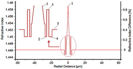
There are some literature reports that revealed the exponential profile would decrease the loss level.18,19 Accordingly, we have used two silica-based dopants with refractive index of 1.4–1.46 in the cladding region. By employing the proposed parameters’ values of the refractive profile given in Table 1, we have proposed a profile as illustrated in Figure 1, showing the refractive index and percentage of the refractive index difference.

Figure 1Exponential refractive index profile of the designed NZDSF.
Parameters |
Regions |
# 1 (Core) |
#2 |
#3 |
#4 |
#5 |
Profile regions |
Exponential |
Gap |
Ring |
Gap |
Clad |
Width |
2.2 |
0.5 |
0.8 |
1 |
58 |
Refractive Index |
1.460 Max-1.446 Min |
1.4448 |
1.45 |
1.4448 |
1.4462 |
Table 1 The proposed parameters’ values of the refractive index profile
The refractive index profile is divided into 5 Regions. The Region 1 forms the core of the fiber with a radius of
with an exponential variation of the refractive index changing from 1.446 to 1.460. The Region 2 is a gap of
with refractive index of 1.4448 between the core and the Region 3 with a width of
and refractive index of 1.45, considered as a refractive index ring at the vicinity of the core in the cladding.
Region 4 is yet another gap between the ring and the cladding with a width of
and refractive index of 1.4448. The final Region 5 is forming the major part of the cladding with a span of 58 and refractive index of 1.4462, as shown in Figure 1.
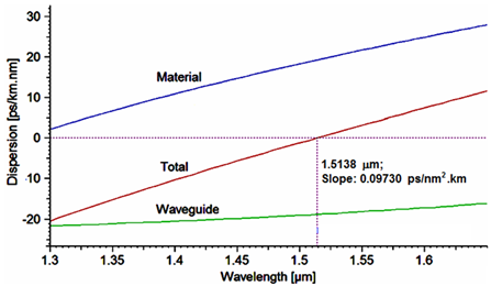
Figure 2 shows the dispersion of the designed profile. As it is noted, total dispersion and dispersion slope are
and
, respectively, at wavelength 1550 nm. The effective area of our profile is
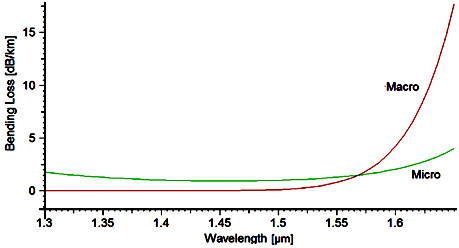
. Because of this large effective area, there will be a limitation in bending, so also in the bending loss, as depicted in Figure 3. Above 1550 nm, the macro-bending loss increases with a higher slope.

Figure 2 Dispersion of the designed NZDSF profile versus wavelength. 1.5138 , Slope: 0.09730 ps/nm2.km.

Figure 3 Bending losses of the designed NZDSF profile versus wavelength.
The macro- and micro-bending losses in this profile are 0.79 and 1.28dB/km, respectively. Material loss is 0.19 dB/km and splices loss in the condition of splicing two matched optical fibers, is 4.77 dB.
We have found that the minimum latency is obtained at the wavelength of 1510 nm which is
. Using Eq. 3 the group index of the above profile is 1.4644 at the wavelength 1550 nm. Replacing this amount in Eqs. 8 and 9 the estimated latency is obtained as
But the latency at the same wavelength is
;so we have
tolerance between the estimated and practical latency.
In Table 2, our obtained results are tabulated and are compared to the data of the large effective area fibers reported in Coning data sheet.
Parameters |
Our model @ |
Corning’s NZDSF @ |
1550 nm |
1310 nm |
1550 nm |
1310 nm |
Group index |
1.4644 |
1.4648 |
1.4693 |
- |
Group delay |
4.885 |
4.886 |
4.901 |
- |
Group velocity (km/s) |
204720.335 |
204664.431 |
204037.608 |
- |
Latency |
4.885 |
4.886 |
4.901 |
|
Dispersion (ps/nm.km) |
3.23 |
-21.59 |
6-Apr |
- |
Effective area |
130 |
60 |
72 |
- |
Material loss (dB/km) |
0.19 |
0.36 |
0.19 |
<0.4 |
Macrobending loss (dB/km) |
0.81 |
1.63 |
<0.5 |
- |
PMD (ps) |
18.06 |
- |
9.5 |
- |
Table 2 Designed values compared to the data of NZDSF reported by Coning Inc
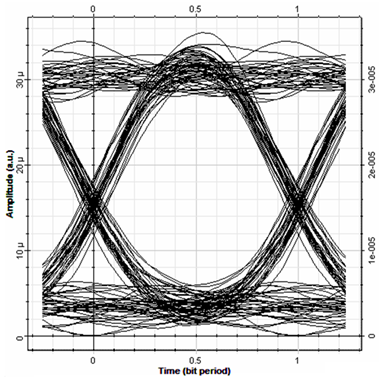
For the next step, we have employed our designed NZDSF in an optical network to evaluate how far the light will be transmitted without using EDFA and DCF and can be detected with desirable quality. For this aim, we have designed an optical network based on an optical transmitter and a receiver with the bit rate of 10Gb/s. The received signal at the distance of 80kmwas monitored by using eye-diagram as shown in Figure 4. The quality factor and minimum bit-error rate of this signal were 10.91 and
, respectively, which are desirable amounts for this distance of transmission.20,21

Figure 4 Eye-diagram of the received signals at the distance of 80 km.
Conclusion
In this study, we have designed an NZDSF with refractive index of 1.4644 at wavelength of 1550 nm which had minimum latency at 1352 nm. In comparison to Corning NZDSF, the latency for the designed NZDSF has improved about
per kilometer The effective area is
and macro-bending loss is obtained as 0.79 dB/km. The dispersion of this fiber is 3.23ps/nm.km which is comparable to Corning NZDSF fiber.
We have employed our designed NZDSF in an optical fiber network in order to evaluate the quality of the received signals from 80 km of our fiber. The results have revealed that without using optical amplifier and DCF, the quality factor and minimum bit-error rate have been obtained as 10.91 and 5.03×10⁻²⁸
respectively.
Acknowledgments
The authors acknowledge the allocated study mission project with the Permit No. 2210, in Communication Technology Dept., at Iran Telecom Research Center.
Conflict of interest
Authors declare there is no conflicts of interest.
References
- Narottam Das. Advances in Optical Communication. UK: Intechopen Limited; 2014.
- Low-Latency Market Data. Ireland: Corvil Insight Inc; 2010.
- Kawanishi T, Kanno A, Yoshida Y, et al. Impact of wave propagation delay on latency in optical communication systems. Proceedings Volume 8646, Optical Metro Networks and Short-Haul Systems V. USA; 2013.
- Mazzarese D. Minimizing latency in long-haul networks. Lightwave. 2011.
- Corning Inc. Corning SMF-28e+optical fiber specification datasheet. 2013.
- Kazumasa A, Ohsono, Tomoyuki Nishio, et al. Low non-linear non-zero dispersion-shifted fiber for DWDM transmission. Hitachi Cable Review. 2000;19.
- Arai S, Akasaka Y, Suzuki Y, et al. Low nonlinear dispersion–shifted fiber. OFC’97 Technical Digest. 1997; 65 p.
- Wandel M, Kristensen P. Fiber designs for high figure of merit and high slope dispersion compensating fibers. J Opt Fiber Commun Res. 2006;3(1):25–60.
- Paula B Harboe, Edilson da Silva, José R Souza. Analysis of FWM penalties in DWDM systems based on G.652,G.653, and G.655 optical fibers. World Academy of Science, Engineering and Technology. 2008;48(12):77–83.
- Kant S, Sahu H, Arora A. Enhanced bend insensitive high effective area NZDS fiber. International Wire and Cable Symposium, Proceedings of the 55th IWCS/Focus. 2010. p. 330–333.
- Li MG, Chen X, Liu A, et al. Limit of Effective Area for Single–Mode Operation in Step–Index Large Mode Area Laser Fibers. Journal of Lightwave Technology. 2009;27(15):3010–3015.
- Siliard P, Molin D. Non–zero dispersion shifted optical fiber having a large effective area. Patent application number: 20110188826; 2011.
- Shizhuo Yin, Kun-Wook Chung, Hongyu Liu, et al. A new design for NZDSF with a large effective area over 100
and low bending and splice loss. Optics Communications. 2000;177(1-6):225–232.
- Sivanantharaj Avaninathan, S Selvedran, et al. An optimized design for NZDSF with reduced nonlinear effects for future optical networks. J Optica Applicata. 2014;44(4):503–519.
- John A Jay. Low signal latency in optical fiber networks. International Wire & Cable Symposium. Proceedings of the 60th IWCS Conference. 2011. p. 429–437.
- Seraji FE, Kiaee MS. Design optimization of NZDSF for low latency in iot optical fiber network. Phys Astron Int J. 2018;2(5):448‒450.
- Faramarz E. Seraji, Razieh Kiaee. A Revisit of Refractive Index Profiles Design forReduction of Positive Dispersion, Splice Loss, and Enhancement of Negative Dispersion in OpticalTransmission Lines. Int J Opt Apps. 2014;4(2):62–67.
- Marc Nikles, Luc Thevenaz, Philippe A Robert. Brillouin Gain Spectrum Characterization in SMF. J Lightwave Technol. 1997;15(10):1842–1851.
- KZ Nobrega, ASB Sombra. Optimum self-phase modulation profile for nonlinear transmission recovery in twin core optical couplers with loss. J Opt Commun. 1998;151:1–3.
- Go Yun Li, K Dimyati. Evaluation of Direct Modulation and External Modulation in Temporal Phase Encoding System. IEEE Malaysia Int Conf; 2013 Nov 26-28; IEEE. 2013. p. 425–455.
- Muthana Y Aldouri, SA Aljunid, R Badlishah Ahmad, et al. BER Performance of RZ and NRZ Data Signals Optical Code Division Multiple Access System Based on and Detection Scheme in Fiber to the Home Network. Optica Apllicata. 2011;21(10): 9–13.

©2019 Seraji, et al. This is an open access article distributed under the terms of the,
which
permits unrestricted use, distribution, and build upon your work non-commercially.


