Due to ever–increasing demands for optical fibers with low–latency used in IoT optical fiber networks, in this theoretical study, a non–zero dispersion shifted fiber (NZDSF) with a particular refractive index which had a minimum latency at 1352 nm is designed. In comparison to a commercial NZDSF, the latency has improved by 0.002
in the designed NZDSF with an effective area of 102
and macro bending loss of
. The dispersion of this fiber is found to be 1.10625ps/nm.km which is comparable to the commercial NZDSF fiber.
We have designed an optical fiber network used in IoT in order to evaluate the quality of the received signals from 50 km of our designed NZDSF fiber. The results have shown that without using optical amplifier and DCF, the quality factor and minimum bit–error rate are obtained as 8.17 and
, respectively.
Keywords: latency, NZDSF, optical networks, optimization
In recent years, dense wavelength division multiplexing (DWDM) networks have been implemented as a result of increasing demands for a massive bandwidth in long–haul systems and internet of things (IoT) optical fiber networks.
During light transmission, there are many parameters which affect the quality of the received optical signals. One of these parameters is the nonlinear effects.1 To overcome nonlinearity effects, large effective area fibers (LEAF) have been employed.2 At the first generation, zero–dispersion shifted fibers (ZDSF) were used to achieve minimum loss and dispersion; but by increasing the number of signal wavelengths in DWDM networks, the effect of four–wave mixing (FWM) was observed which induces inter–channel crosstalk during the light transmission in optical links.3–4
Besides ZDSFs, non–zero dispersion shifted fibers (NZDSF) have been designed to avoid the phase matching condition and reduce the effects of FWM in optical networks.2,4 By using NZDSF, we may obtain a large effective area which minimizes the nonlinear effects;2 however, larger effective area makes fiber more sensitive to bending loss. So, the choice of optimum parameters during the design of an optical fiber are very important.
Using optical fibers with very large effective area may cause a very high mode field diameter (MFD).5 In order to avoid this outcome, effective area must be limited and optimized. In a study, the upper limit of effective area in a single mode fiber was reported around 370
.6 In a study, an NZDSF with effective area of 95
, dispersion slope of
and bending loss of 0.005 dB has been designed.7
An NZDSF with effective area of
, dispersion of 4ps/nm.km, dispersion slope of
and bending loss of 0.0013dB/km at the wavelength 1550nmwas designed in a report.8 One do pant has been employed in the core region of this optical fiber.
In another study, these amounts have been optimized by using three dopants regions with different refractive index in the core; then the effective area was increased up to
and the bending loss was decreased down to
.9 At the wavelength of 1550nm, the dispersion, effective nonlinear refractive index and 1st order PMD were
,
and
, respectively.
Another important parameter in the next generation transmission communication systems is the latency. As it is reported before, the typical group delay in a conventional single mode fiber is about
.10 Regarding optical network latency due to physical layer, much works have not been reported in the literatures. In our study, we have designed an NZDSF with positive dispersion with a minimal latency and an optimum effective area.
We have started our study by using the Corning conventional NZDSF with a dispersion of 4 ps/nm.km, effective area of
and effective group refractive index of 1.4693. By assuming above values, we can calculate the latency
of the corresponding optical fiber by the following expressions at wavelength 1550 nm:
(1)
(2)
where
is the phase velocity of light in a specific medium,
is the velocity of light in a vacuum,
is the effective group refractive index, and
is the latency of optical signals at wavelength of 1550 nm.
As we know, the latency of light in vacuum is
; so we should find a way to minimize the latency of light in optical fiber used as a transmission medium in an optical fiber network. For this purpose, we have designed an NZDSF with a core of exponentially changing refractive index profile.
As we know, adding Germanium or Fluorine atoms would increase or reduce the refractive index of pure silica, respectively. The refractive index
of
mole–percentage doped material can be defined as follows:11
(3)
where
is the refractive index of the host material and
is the refractive index of doped material. Thus, the exponential profile function of the core can be shown as follows:11
(4)
where
and
are the refractive indices at
and
, respectively, and
. In order to calculate the latency of this fiber, we should find the group delay of light with refractive index of
for the distance of
by the first frequency–derivation of the propagation constant as follows:12
(5)
The total dispersion of light is calculated by the following expression:
(6)
As we know, more effective area would decrease the none–linearity effects; so it is important to minimize the none–linearity of fiber in our design. Assume that
is the optical mode field distribution, then the effective area can be defined by using the following expressing:13
(7)
Also, the nonlinear effective index can be calculated in a fiber as follows:
(8)
where
is the user–defined spatially dependent nonlinear refractive index of the various layers of the fiber and
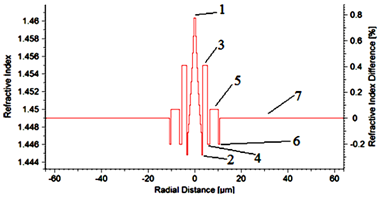
is the normalized mode field pattern. We have started our study by employing the profile of an optical fiber which was used to achieve a high negative dispersion in a DCF.14 Since our first purpose was to design a positive dispersion NZDSF, we have changed the core profile into an exponential function. There are some literatures that showed the exponential profile would decrease the loss level.15,16 Further, we have used two silica–based dopants with refractive index of 1.44–1.45 in the cladding region. To increase the density of the silica glass, Germanium dioxide (GeO2) is added to the substrate glass, while for decreasing the density, Fluorine (F) is used. Our designed profile is shown in Figure 1.

Figure 1 Exponential refractive index profile.
The core with a radius of
has a refractive index changing linearly from 1.4615 to 1.44692, marked as region 1. Regions 3, 5, and 7 have refractive indices of 1.455, 1.45, and 1.449 with the radius of 2, 3.7, and
, respectively. The refractive index of Regions 4 and 6 are 1.45 with radii of 1.0 and
, respectively. Also, Region 2 is formed with refractive index of 1.4448 and radius of 0.02
.
We have found that the minimum latency of
is obtained at the wavelength of 1352 nm. Using Equation 3, the group index of the above profile is found as 1.46888. Replacing this amount in Equations 1 and 2, the estimated latency is obtained as
. So, we have
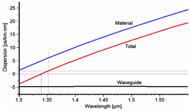
tolerance between the estimated and practical latencies. Figure 2 shows the dispersion of the designed profile. As it’s noted, total dispersion and dispersion slope are 1.10625 ps/nm.km and
, respectively, at the wavelength of 1352 nm.

Figure 2 Dispersion at the wavelength of 1352nm.
The effective area of the profile is calculated as
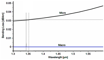
. Because of the large effective area, there will be a limitation in bending condition. The corresponding macro–and micro–bending losses are depicted in Figure 3. The macro–and micro–bending losses in this profile are obtained as
and 0.031 dB/km, respectively, at the wavelength of 1352 nm.

Figure 3 Bending loss at the wavelength of 1352nm.
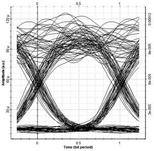
For the next step, we have employed our designed NZDSF in an optical network to evaluate how far the light will be transmitted and can be detected with desirable quality without using EDFA and DCF. For this aim, we have designed an optical network based on an optical transmitter and a receiver with the bit rate of 10 Gb/s. The received signal at a distance of 50 kmwas monitored by using the eye–diagram, as shown in Figure 4. The quality factor and minimum bit–error rate of the received signal are 8.17 and  , respectively, which are desirable amounts for this transmission distance.17–19

Figure 4 Eye–diagram of the received signals at a distance of 50km.
In this study, we have designed an NZDSF with core refractive index of 1.46888 which had a minimum latency at 1352 nm. In comparison to Corning NZDSF, the latency has improved by 0.002
. The effective area is found to be
and macro bending loss is
. The dispersion of this fiber is 1.10625 ps/nm.km which is comparable to Corning NZDSF fiber.
In addition, we have presented an optical fiber network in order to evaluate the quality of the received signals from 50 km of our designed fiber. The results have shown that without using optical amplifier and DCF, the quality factor and minimum bit–error rate are obtained as 8.17 and
respectively.


![]() , respectively, which are desirable amounts for this transmission distance.17–19
, respectively, which are desirable amounts for this transmission distance.17–19