Optical Fiber as a transmission medium is now playing a major role in communication industry. A low latency is a vital element for any network design. Optical path optimization is the key to designing a network with low latency. Group delay coefficient is a fiber design variable used to optimize the propagation time. Dimensions, material composition and refractive-index profile, dispersion, and non-linearity of the fiber should be carefully selected to provide a satisfactory design for a given program. In this paper, several refractive index profiles are designed, using the OptiFiber software. Different refractive index profiles with triangular core, exponential core and ring, with exponential core and parabolic ring, and two-segmented core are considered to design SMFs for low latencies transmissions. Among other designed SMFs, two-segmented core fiber with core profile transformation is compared to the commercially available product, whose latency is improved by 0.73% with macro- and micro-bending losses of 3.29592e+2 dB/km and 0.0532336 dB/km, respectively, total dispersion of 16.7981 ps/nm.km, and mode field diameter (MFD) of 11.9422 µm at the wavelength of 1550 nm.
Keywords: design, low latency, refractive index profile, dispersion, optical transport network
The latency in optical networks has recently attracted a lot of attentions among researchers and industries. This is especially evident in financial and commercial firms that are critical to the speed of transactions. A latency of a fraction of a second in trade can turn into millions of dollars losses or lost opportunities.1,2 A latency in the optical fiber communication systems (OFCS) explains how much time it takes to transmit data from a sender to a recipient. The latency of the physical layers in optical fibers networks consists of three main parts: fiber, optical components, and optical-electrical components. In the OFCS, the lag time is obtained by dividing the fiber length by the speed of light in the fiber core.3 In addition to fiber-induced latency, there are other building blocks that affect the total data transmission time.1,2 These elements include optoelectronic conversions, switching and routing, signal reconstruction, amplification, dispersion compensation, polarization dispersion compensation, data packet, digital signal processing, protocols, and forward error correction.1 Therefore, some companies use a logical diagnosis for low latency networks solutions.4
From one of the fiber parameters, i.e., the group index, is used as a fiber design variable to optimize the low propagation latency time.5 The lower refractive index means more speed and hence lower signal latency, depending on the fiber waveguide, material system, design, signal wavelength, spectral properties and the surrounding environmental parameters, such as temperature and pressure. Some optical fibers have lower group index coefficient, such as photonic crystal fibers (PCFs) can have a lower refractive index and can let light propagate much faster than standard single-mode fibers (SMF).6 For example, hollow core fiber (HCF) may provide up to 31% reduction in latency than older fibers.7,8 But there is a problem that the attenuation in HCF fibers is much higher compared to the SMFs of a previously used fabrication (for SMF and HCF fibers, the losses are 0.2 dB/km and 3.3 dB/m at wavelength 1550 nm), respectively.9
The chromatic dispersion (CD) occurs due to the different wavelengths of light propagating in optical fibers, which can be compensated using the dispersion compensating module (DCM) made of dispersion compensating fibers (DCF) or Bragg grating fibers (FBG).10 To avoid the need to compensate for chromatic dispersion or to reduce the length of the DCF fiber, use of fiber optics with a small amount of CD required. For example, non-zero dispersion shifted fibers (NZDSFs) are available to simplify dispersion compensation when constructing a wideband channels. The NZDSF fiber parameters are defined in Recommendation ITU-T G. 655.11 The DCM with the FBG can provide some compensation for a 100 km or so without any sign of latency, effectively eliminating all additional latency that a DCF-based network add to it.12 In FBG, when these spectral components are combined, the pulse is compressed and the effects of fiber dispersion are eliminated.13 A solution to avoid excessive latency in case of a need for amplification, the Raman amplifier with/without EDFA is used. This combination boosts the maximum signal with a minimum latency. Raman amplifiers use a variety of optical features to amplify the optical signal.5,14 There are a few advanced fiber optics technologies to reduce group delays. For example, with regard to fused silica as a fiber optic material, the refractive index decreases with wavelengths.
The signals with a wavelength longer than 1550 nm in fiber experience a lesser group delays. At the same time, the varying absorptions of SiO2 lattice at these wavelengths increases the loss and requires an amplifier that in turn increases the network latency. Another approach is the use of glasses that exhibit low refractive index characteristics with proper transmission at these wavelengths. The samples of these glasses are based on fluoride material, including ZBLAN glass.15 A final option is to reduce the signal latency is use of photonic crystal fibers. In these fibers, compared with Germanium silica fiber, high loss of 1.2 dB/km is reported.16 In addition, the equipment and methods for connecting and splicing PCF fibers have not yet been developed. Recently, we have reported designs of a non-zero dispersion shifted fibers (NZDSF) used as the transmission medium with minimal latency in an optical network. The latency were improved by 0.01 μs17 and 0.002 μs.18 A literature survey has revealed that much academic research works on the latency and IoT networks have not been reported till date. In this paper, by using OptiFiber software, attempts are made to reduce the pulse propagation latency by modifying the profile of the core refractive index and the cladding of a sample of commercially available optical fibers, by taking into account the parameters such as bending losses, dispersion, fiber MFD, while assuming the designed fiber to remain single-mode.
Group delay, dispersion, attenuation, and MFD
In this section, the parameters to be considered in our design are presented as follows.19
By considering propagation constant, angular frequency of the light, and the propagation length, the group delay time is then calculated as follows:
(1)
where is the refractive index,
denotes the wavelength of light,
shows the velocity of the light in a vacuum, and
represents the wave number, therefore, we can write:
(2)
The dispersion causes the pulse to spread along the transmission line and thus limiting the transmission capacity of the optical communication networks.20,21 The dispersion coefficient is defined as:
(3)
In general, the dispersion in an optical fiber is determined using the following procedure:22
(4)
where
is the optical wavelength. The second derivative of the propagation constant with respect to the angular frequency of the light is equal to:
(5)
where
is the core effective index,
represents the cladding index,
denotes the effective relative index difference between the core and the cladding, and
. The total disperesion, due to the material and the the waveguide dispersions, is obtained as follows:22
(6)
where
is the attenuation coefficient of fiber in the transmission line due to the bending radius, which is large compared to the diameter of the fiber:23,24
(7)
where
is the field radius of the principle mode,
bending radius, fiber core radius,
normalized frequency, and f, W
are given as follows:
(8)
where
represents the refractive index profile,
, and
, denote the maximum and minimum refractive indices, respectively. The parameters
and
are expressed as follows:
(9)
The macrobending loss is defined by considering the attenuation coefficient as follows:
(10)
where L is the length of the transmission line in km, Pin denotes the input power and Pout represents the output power at the end of the transmission line. The mode field diameter (MFD) is referred to as the intensity distribution width, which is an important parameter associated with the field of light. The MFD provides useful information on cabling, including large losses and fine-tuning. The effective area of the fibers is directly related to the nonlinearity of the fiber. The mode field diameter (MFD) of the near-field, known as Petermann-I, is the intensity of the near-field
close to
times the maximum intensity. The light intensity on the core axis, that is, at the radius r=0 in SMFs, has the highest value. The near-field
and the far-field
, known as Petermann-II, are expressed, respectively as follow:25
(11)
where
represents the far field distribution of the light state.25
Triangular Core and Ring profiles
Figure 1 shows the refractive index of the fiber that is designed with structural data of a commercial fiber with a triangular core of four regions by using Optifiber software. The region #1 is the fiber core with a radius of 1.3 and a refractive index varying from 1.446692 to 1.4684. The cladding of the fiber is divided into regions #2, #3, and #4, having widths of 1, 1.8, and 56.6
, respectively. The total fiber diameter is 125 . The refractive index of the ring (region #3) is 1.45247 with triangular shape. The wavelength of 1550 nm has been selected.26 The designed fiber profile shown in Figure 1 is single-moded. The group delay diagram of the fiber is shown in terms of wavelength in Fig. 2, where the group delay decreases with increasing wavelength and its value at 1550 nm is 4.93275
/km. For the design of a fiber with lesser latency, one can modify the core and cladding geometries. In the original fiber shown in Figure 1, the shape of the core and the ring are made triangular. By changing the shape of the core and the cladding to exponential, parabolic, and triangular, by keeping the value of other parameters of the designed fiber unchanged, we have determined the fiber parameters including latency, material dispersion, bending losses, and MFD at 1550 nm, as given in Table 1.
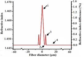
Figure 1 Refractive index profile of the designed fiber with triangular core and cladding.
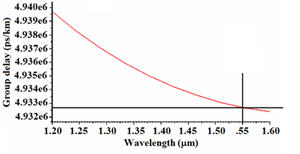
Figure 2 Group delay (Latency) in terms of wavelength.
Profile types |
Latency (Group delay)
|
Dispersion (ps/nm.km) |
Bending losses (dB/km) @1550 nm |
MFD
|
|
|
Material |
Total |
Macro |
Micro |
|
Triangular core and ring (Ref.) |
4.93275 |
20.397 |
-7.46203 |
4.99E-28 |
0.014563 |
6.09748 |
Table 1 The calculated parameters of the fiber with triangular core and ring
Exponential core and ring profile
Of course, given the fact that the fiber has to remain single-moded, we have come to an intermediate conclusion that if the fibers and rings are exponential (Figure 3), the latency will be less than that of the original fiber in Figure 1. As compared to the fiber of Figure 1, the dispersion value has decreased by -8.63014 ps/nm.km, but, the value of material dispersion has increased to 20.7912 ps/nm.km, the macrobending loss to 1.1638e-12 dB/km, microbending loss to 0.0353171 dB/km, and finally MFD to 6.940 as shown in Table 2. The latency for this fiber is obtained as 4.92090.
Profile types |
Latency (Group delay)
|
Bending losses (dB/km) @1550 nm |
Dispersions (ps/nm.km) |
MFD
|
|
|
Macro |
Micro |
Material |
Total |
|
|
|
|
|
|
|
|
Exponential core/ring |
4.9209 |
1.16E-12 |
0.035317 |
20.7912 |
-8.63014 |
6.9402 |
Table 2 Parameters values of the designed fiber with exponential core/ring
Exponential core and parabolic ring profiles
Another approach for the profile variation of the fiber in Figure 3 is to use a depressed ring, where the fiber structure will have four regions, as shown in Figure 4. The region #1 constitutes the fiber core with a radius of 3.1 and a refractive index ranging from 1.446692 to 1.4684. The cladding of the fiber is divided into regions #2, #3, and #4, having a width of 1, 1.8, and 56.6 μm, respectively, which is the same as that of the reference fiber (Figure 1). The refractive index of the ring (region #3) is 1.44 and depressed. In this design, it is also intended that the fiber remains in single mode regime. In this design, the fiber with exponential core and depressed parabolic ring has the least latency of 4.92590
, which is, of course, lower than the latency of the reference fiber. Worthy to note that other parameters such as the dispersion has increased to -4.2269, microbending loss to 0.744189 dB/km, macrobending loss to 4.98261e-9 dB/km, and MFD to 6.14963
as listed in Table 3.
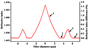
Figure 3 Profile of the designed fiber with exponential core and ring.

Figure 4 Profile of the designed fiber with exponential core and parabolic ring.
Profile types |
Latency (Group delay)
|
Bending losses (dB/km) @1550 nm |
Dispersions (ps/nm.km) |
MFD
|
|
|
|
|
|
|
|
Macro |
Micro |
Material |
Total |
|
|
|
|
|
|
|
|
Exponential core/depressed parabolic ring |
4.9259 |
4.98E-09 |
0.744189 |
20.7541 |
-4.2269 |
6.14963 |
Table 3 Parameters values of the designed fiber with exponential core/depressed parabolic ring
Two-segmented core profile
To further obtain a fiber profile with a lower latency level, we can design a different core shape in the form of Figure 5, whose two-segmented core is divided into two regions #1 and #2. The region #1 is 0.6 with an exponential refractive index in the range of 1.468 to 1.452 and total core size of 3.1
which is equal to the reference fiber size. The region #2 is 2.5
in size with a refractive index of 1.45. The distance between the ring and the core of the region #3 is 1
with a fixed refractive index of 1.446692. The width of the ring #4 is 1.8
and exponential with a refractive index of 1.446692 to 1.4524. The radius of the cladding of the fiber is the fifth region of size 56.6
with a refractive index of 1.446692.
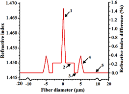
Figure 5 Refractive index profile of the designed fiber with two-segmented core.
The fiber parameters of the designed two-segmented core are presented in Table 4. By comparing Tables 1 and 4, fiber with two-segmented core has a lower latency of 4.89988 but other parameters such as dispersion, bending losses, and its MFD relative to fiber in Figure 2 has increased. The latency (group delay ps/km) in terms of the distance between the core and the ring (width of region #3 in Figure 5) is plotted in Figure 6. We note that latency is directly related to this width, thus, by reducing the width, the latency will increase and the MFD value crosses the single-mode value. In our final attempt, we have tried to modify the structural parameters to bring back the designed two-segmented core fiber to operate in single-mode regime with the following profile alteration, as shown in Figure 7. The profile includes the region #1 of width 0.6 with exponential refractive index from 1.4684 to 1.452, the region #2 of width 2.5
with a constant refractive index of 1.45, the region #3, i.e., the distance between the ring and the core of width 0.2 (minimum size) with a constant refractive index of 1.446692, and the region #4 of width 1.8 with refractive index exponentially changing from 1.446692 to 1.4524. Finally, the fifth region, i.e., the cladding region with a width of 57.4
and refractive index of 1.446692. The characteristic parameters of this designed SMF are listed in Table 5. In this case by changing the width of the region #3 from 1 to 0.2
the single-mode operation is achieved. As we can note from the Table 5, in two-segmented core profile, by reducing the distance between the core and the ring, among other profiles, a minimum latency of 4.89805
is obtained. However, it should be noted that other calculated parameters such as bending losses, dispersion, and the MFD, with respect to the reference fiber, have increased.
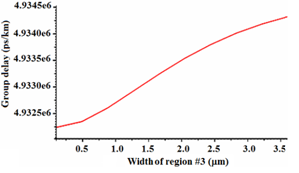
Figure 6 The group delay versus the distance between the core and the ring.
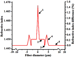
Figure 7 Refractive index profile of the designed fiber with two-segmented core for 0.2 width of region #3.
Profile types |
Latency (Group delay)
|
Bending losses (dB/km) @1550 nm |
Dispersions (ps/nm.km) |
MFD
|
|
|
Macro |
Micro |
Material |
Total |
|
Two-segmented core |
4.89988 |
1.95E+03 |
0.115935 |
21.4066 |
17.0987 |
13.0499 |
Table 4 Parameters of the designed fiber with two-segmented core
Profile type |
Latency (Group delay)
|
Bending losses (dB/km) @1550 nm |
Dispersions (ps/nm.km) |
MFD
|
|
|
|
|
|
|
|
Macro |
Micro |
Material |
Total |
|
|
|
|
|
|
|
|
Two-segmented core |
4.89805 |
3.30E+02 |
0.053234 |
21.3442 |
16.7981 |
11.9422 |
Table 5 The parameters of the designed SMF with two-segmented core with width of the region#3 = 0.2
In an optical networks, fiber is not always tracked along the direct path between two locations, so the cost of deployment of the fiber can be very high. Some operators have created low-latency fiber paths between major financial centers, and have used low-latency systems to run these links. This is an expensive measure and is likely to be possible only in the core financial services where the willingness to pay is high enough to support the business flow. In most cases, the fiber path and the latency are fixed with complexity and cost. The proper choice of passive optical components, such as optical cables and dispersion compensation approaches, one can further reduce network latency. The large effective area increases the MFD in optical fibers; and high-MFD fibers make the fiber more susceptible not only to bending loss,27 but also leads to the polarization mode dispersion (PMD).26 Considering the results of fiber design, if we consider a 100-km route, the latency for the reference fiber will amount to 0.493275 and for the designed fiber will be 0.489805 . Therefore, the latency of 100 km distance is decreased by almost 0.73%. As stated, a one-millisecond reduction in the transmission paths of financial institutions can bring back million dollars profit. It should be noted, however, that the reference fiber has a dispersion of -746.20 ps/nm.km along 100 km path, but the designed two-segmented core fiber has dispersion of 1679.81 ps/nm.km. As it is observed, the amount of dispersion has significantly increased. Regarding total loss, it should be noted that direct network routing can minimize the amount of losses caused by the optical path. Therefore, there should be a trade-off between the latency and the total loss in an optical fiber network.
In Table 6, we have compared the two-segmented designed fiber to a commercial fiber, which has been selected as design reference. The latencies of the two-segmented core fiber and the reference fiber are plotted in Figure 8 for a comparison. We note that over almost all the designated wavelengths, the latencies of the designed SMF are less than that of the reference fiber. The minimum latency of the designed optical fiber is obtained as 4.89775 at wavelength of 1465 nm, whereas that of the reference fiber is 4.93360 , i.e., 0.73% improvement of latency. Above wavelength 1550 nm, the latency of the reference fiber at the lowest of 4.9325 is obtained at wavelength 1600 nm, whereas that of the designed fiber is 2.8985.
Refractive index profile |
Designed two-segmented core SMF |
Reference fiber26 |
Wavelength (nm) |
1550/1465 |
1550/1465 |
Latency (Group delay)
|
4.89805/4.89775 (min) |
4.93275/4.9336 |
Total dispersion (ps/nm.km) |
16.7981 |
-7.462 |
Material dispersion (ps/nm.km) |
21.3442 |
20.397 |
MFD
|
|
11.9422 |
6.09748 |
Bending loss (dB/km) |
Macro |
3.30E+02 |
4.99E-28 |
|
Micro |
0.053234 |
0.014563 |
Table 6 Comparison of parameters values of the designed two-segmented core fiber with the reference fiber
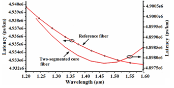
Figure 8 The comparison of the group delay of the designed two-segmented core fiber and the reference fiber versus wavelength.


