The use of the multi-layer longitudinal piezo engine for nano- and micro displacements is promising in nano biomedical research for the compensation of gravitational and temperature deformations, precise alignment,1−10 Nano pumps, microsurgery, scanning microscopy, adaptive optics, interferometers.8−38
Increasing the range of displacement to tens of micrometers is achieved by using the multi-layer longitudinal piezo engine in the form the composite, stack or block piezo engine.1−8
At present the use of the multi-layer longitudinal piezo engine with parallel and coded control is relevant, which requires determining the characteristics of this piezo engine. The application of the multi-layer longitudinal piezo engine at coded control makes it possible to effectively use electromechanical digital-to-analog conversion proportional to the control code for nano- and microdisplacements.11−34
In contrast to the simple piezo engine the multi-layer longitudinal piezo engine in static without load has the range of the movement increased in n times, where n – the number of the piezo layers. The characteristics of the multi-layer longitudinal piezo engine for parallel and coded control are calculated by applied method of mathematical physics.
Characteristics multi-layer longitudinal piezo engine at parallel control
Structurally the multi-layer longitudinal piezo engine, depending on the manufacturing technology, can be made in the form: the composite piezo engine made of individual elastically pressed piezo plates; packaged or block piezo engine made of piezo plates sintered using silver paste; the composite piezo engine made of the piezo packages with elastic reinforcement; the glued multi-layer piezo engine made of the piezo plates; the multi-layer piezo engine with the layers by using thick-film or thin-film.1–18
The equation3−6 of the inverse longitudinal piezo effect has the form
here
− the relative displacement, the electric field stress, the mechanical stress, the piezo module, the elastic compliance with
, index 3 for 3 axis.
We have the equation of the mechanical characteristic at parallel control in the form
and after the transformation we have the equation of the mechanical characteristic
here
− the length,
− the rigidity of the of the multi-layer longitudinal piezo engine,
− the displacement,
− the force. Let us consider the mechanical characteristic on Figure 1 of the multi-layer longitudinal piezo engine at parallel control from ceramic PZT.
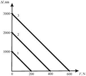
Figure 1 Mechanical characteristic of multi-layer longitudinal piezo engine at parallel control.
The measurements of the mechanical characteristic were made on the Universal testing machine UMM-5 Russia in the range of working loads under mechanical stresses in the multi layered longitudinal piezo engine up to 100 MPa. At
= 0.4 nm/V, n = 50,
= 2×10⁸ N/m for 1) U = 50 V; 2) U = 100 V; 3) U = 150 V the parameters of the multi-layer longitudinal piezo engine from ceramic PZT are determined on Figure 1 in the form 1)
= 1000 nm,
= 200 N; 2)
= 2000 nm,
= 400 N; 3)
= 3000 nm,
= 600 N. The discrepancy between the experimental data and the calculation results is 10%.
The displacement of the multi-layer longitudinal piezo engine at parallel control and elastic load on Figure 2 has the form
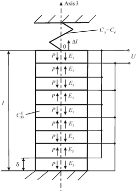
Figure 2 Multi-layer longitudinal piezo engines at parallel control and elastic load.
Here
− the force of initial compression by the elastic element;
− the mechanical stress of the initial reinforcement in the piezo engine;
− the rigidity of the reinforcing element;
− the load rigidity.
Consequently, the equation for the adjustment characteristic of the multi-layer longitudinal piezo engine at parallel control and elastic load has the form
For
and
the equation the adjustment characteristic on Figure 3 of the multi-layer longitudinal piezo engine at parallel control and elastic load has the form
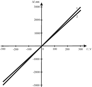
Figure 3 Adjustment characteristic at parallel control and elastic load.
The adjustment characteristics on Figure 3 are determined by using electronic measuring system of displacement Model 214 Russia for the multi-layer longitudinal piezo engine from PZT for parallel control and elastic load at
= 0.4 nm/V, n = 25,
= 4×10⁸ N/m,
for 1)
; 2)
= 0.4×10⁸ N/m with error 10%.
Characteristics multi-layer longitudinal piezo engine at coded control
The length of the multi-layer longitudinal piezo engine at coded control has the form
The maximum displacement of the multi-layer longitudinal piezo engine at coded control has the form
here
is the number of the piezo layers.
In static conditions at the force
and the binary code
we have displacement of the multi-layer longitudinal piezo engine at coded control in the form
Therefore, its displacement has the form
We have the mechanical characteristic at coded control11−34 in the form
after transformation, the normalized mechanical characteristic has the form
here
.
Consequently, the equation for the adjustment characteristic of the multi-layer longitudinal piezo engine at coded control and elastic load on Figure 4 has the form
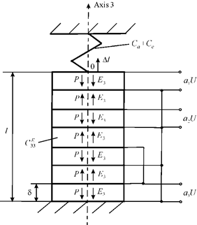
Figure 4 Multi-layer longitudinal piezo engines at coded control and elastic load.
Therefore, the displacement of the multi-layer longitudinal piezo engine elastic load has the form
here
is the coefficient
The measurements of the parameters mechanical characteristic were made on the Universal testing machine UMM-5 Russia for the multi-layer longitudinal piezo engine from PZT for coded control at
= 0.4 nm/V, n = 7,
= 8×10⁸ N/m, and U = 200 V for 1)
= 1,
= 0,
= 0; 2)
= 1,
= 1,
= 0; 3)
= 1,
= 1,
= 1. The maximum displacements and the maximum forces on Figure 5 are obtained 1)
= 80 nm,
= 64 N; 2)
= 240 nm,
= 192 N; 3)
= 560 nm,
= 448 N with error 10%.
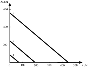
Figure 5 Mechanical characteristic at coded control.
Thus, the adjustment and mechanical characteristics of the multi-layer longitudinal piezo engine at parallel and coded control are found.


