Mini Review Volume 4 Issue 6
Lodz University of Technology, Poland
Correspondence: Jerzy Zajaczkowski, Lodz University of Technology, 116 Zeromskiego Street, 90-924 Lodz, Poland
Received: August 10, 2017 | Published: November 19, 2018
Citation: Zajaczkowski J. Mathematical modelling of direct drive of card machine drum. J Textile Eng Fashion Technol. 2018;4(6):364-366. DOI: 10.15406/jteft.2018.04.00166
The paper is concerned with the mathematical modelling of a directly driven card machine drum. The equations of the motion are derived taking account of an interaction of a drum and the electric motor.
The problem of vibration of cylindrical shells is technically important. The equations of the motion can be found in works.1–6 The natural vibrations have been studied in papers.7–9 The vibrations of rotating shells have been investigated in papers.10,11 The phenomena of bifurcation and chaos in externally excited circular cylindrical shells have been reported in work.12 The stress and transverse deflection of a card machine drum, in a form of a cylindrical shell with wound wire, have been calculated in.13 The purpose of this work is to formulate a mathematical model of a direct drive of a card machine drum.
The rotating shell of mean radius r is shown in Figure 1. Here, m denotes unit mass, g - gravity acceleration and t - time. The rotation angle of shell is denoted as α, the longitudinal and the angular co-ordinates of shell elements are denoted as x and φ. The longitudinal, circumferential and radial components of the shell surface deflection are denoted as u, v and w respectively.
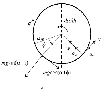
The components of the acceleration of the shell element have the form
av=∂2v∂ t2−2dαd t∂ w∂ t+d2αd t2(r−w)−(dαd t)2vav=∂2v∂t2−2dαdt∂w∂t+d2αdt2(r−w)−(dαdt)2v
aw=∂ 2w∂ t2+2dαd t∂v∂ t+d2αd t2v+(dαd t)2(r−w)aw=∂2w∂t2+2dαdt∂v∂t+d2αdt2v+(dαdt)2(r−w)(1)
Taking into account the inertia, damping and gravity forces, the loading of an element can be written as
qx=−c1∂u∂t−m∂2u∂t2qx=−c1∂u∂t−m∂2u∂t2
qϕ=−c2∂ v∂ t−m(∂2v∂ t2−2dαd t∂ w∂ t+d2αd t2(r−w)−(dαd t)2v)+mgcos(α+ϕ)−qsδ(−α)qϕ=−c2∂v∂t−m(∂2v∂t2−2dαdt∂w∂t+d2αdt2(r−w)−(dαdt)2v)+mgcos(α+ϕ)−qsδ(−α)
qz=−c3∂ w∂ t−m(∂ 2w∂ t2+2dαd t∂v∂ t+d2αd t2v+(dαd t)2(r−w))−mgsin(α+ϕ)+qnδ(−α)qz=−c3∂w∂t−m(∂2w∂t2+2dαdt∂v∂t+d2αdt2v+(dαdt)2(r−w))−mgsin(α+ϕ)+qnδ(−α)(2)
Here, (c1, c1, c1) are coefficients of damping. The internal forces are assumed to be of the form
N'ϕ=m(dαdt)2r2
N'x=Nx1+Nx2cosϕ
N'xϕ=0(3)
The internal torque is
Ms(x)=mx∫02π∫0(∂2v∂ t2−2dαd t∂ w∂ t+d2αd t2(r−w)−(dαd t)2v)(r−w)rdϕdx(4)
The integration over entire length L of the shell gives the driving torque Ms. The angular acceleration is found as
d2αd t2=Msmr−L∫02π∫0((∂2v∂ t2−2dαd t∂ w∂ t−(dαd t)2v)(r−w))dϕdxx∫02π∫0(r−w)2dϕdx(5)
The components of the shell surface deflection can be expressed in the form
u(x.ϕ,t)=UTu, v(x.ϕ,t)=VTv, w(x.ϕ,t)=WTw (6)
Where
Tu=[T(0)un(t)T(CN)un(t)T(SN)un(t)], Tv=[T(0)vn(t)T(SN)vn(t)T(CN)vn(t)], Tw=[T(0)wn(t)T(CN)wn(t)T(SN)wn(t)],(7)
U=[U(0)n(x), U(CN)n(x)cosNϕ , U(SN)n(x)sinNϕ] ,V=[V(0)n(x), V(SN)n(x)sinNϕ, V(CN)n(x)cosNϕ ] ,W=[W(0)n(x), W(CN)n(x)cosNϕ , W(SN)n(x)sinNϕ] ,(8)
Un(x)=[U1(x), U2(x), . . . , Un(x)] ,Vn(x)=[V1(x), V2(x), . . . , Vn(x)] ,Wn(x)=[W1(x), W2(x), . . . , Wn(x)] , (9)
For n=1,2,3,...nmax, N=1,2,3,...Nmax.
Substituting (6-9) into equation (5) and carrying out the integration (5), one obtains
d2αd t2=(Msmr−ˉVd2Tvd t2r+2dαd tˉWdTwd tr+(dαd t)2ˉVTvr+〈¯VTW,d2Tvd t2TTw〉−2dαd t〈¯WTW,dTwd tTTw〉−(dαd t)2〈¯VTW,TvTTw〉)2πLr2−2rˉWTw+〈¯WTW,TwTTw〉,
L∫02π∫0( )dϕdx=¯( ), 〈A,B〉=∑r∑cArcBrc.(10)
The partial differential equations governing the motion of shell element will now be replaced by ordinary differential equations using Ritz-Galerkin. Let’s pre-multiply those equations4,5 by the transposition of functions (8) and then integrate of the resultant expressions by parts with the use of the forces-displacement relationships and boundary conditions
2π∫0l∫0UT(∂Nx∂x+1a∂Nϕx∂ϕ−Qx∂2w∂x2−Nxϕ∂2v∂x2)dxdϕ+
2π∫0l∫0UT(−Qϕa(∂v∂x+∂2w∂x∂ϕ)−Nϕa(∂2v∂x∂ϕ−∂w∂x)+qx)dxdϕ=0,
2π∫0l∫0VT(1a∂Nϕ∂ϕ+∂Nxϕ∂x+Nx∂2v∂x2−Qxa(∂v∂x+∂2w∂x∂ϕ))dxdϕ+
+2π∫0l∫0VT(Nϕxa(∂2v∂x∂ϕ−∂w∂x)−Qϕa(1+∂va∂ϕ+∂2wa∂ϕ2)+qϕ)dxdϕ=0,
2π∫0l∫0WT(∂Qx∂x+1a∂Qϕ∂ϕ+∂∂x(Nxϕ(va+∂wa∂ϕ))+∂∂x(Nx∂w∂x))dxdϕ+
+2π∫0l∫0WT(Nϕa+∂∂ϕ(Nϕa(va+∂wa∂ϕ))+∂∂ϕ(Nϕ xa(∂w∂x))+qz)dxdϕ=0. (11)
As a result of the integration, we obtain a set of three ordinary differential equations of second order
K11Tu+K12Tv+K13Tw+K(1)12(dαdt)2Tv+K(1)13(dαdt)2Tw+C11dTudt+M11d2Tudt2=F1,
K21Tu+K22Tv+K23Tw+K(1)22(dαdt)2Tv+K(2)23d2αdt2Tw+C23dαdtdTwdt++C22dTvdt+M22d2Tvdt2+M24d2αdt2+F2ccosα+F2ssinα+F2(α)=0,
K31Tu+K32Tv+K33Tw+K(1)32(dαdt)2Tv+K(1)33(dαdt)2Tw+K(2)32d2αdt2Tv++C32dαdtdTvdt+C33dTwdt+M33d2Twdt2+F3ccosα+F3ssinα+F3(α)=0.(12)
Introducing matrices of three times higher order, than the matrices in equations (12), these set can be rewritten as one equation
Md2Tdt2+CdTdt+KT+(dαdt)2K(1)T+d2αdt2K(2)T+C(1)dαdtdTdt+Fccosα+Fssinα+F(α)=0(13)
Where T=[Tu,Tv,Tw].
Adding now equation governing the driving torque of the motor
dMsdt=1Ts(Cs(Ωs−dαdt)−Ms)(14)
We obtained the set of three equations (10,13,14) from which angle of drum rotation α, components of elastic deflection T (7-9)and driving torque Ms can be found through numerical integration. Similar calculations were performed by the author for a spindle directly driven by three-phase electric motor.14
None.
Author declares there is no conflict of interest.
©2018 Zajaczkowski. This is an open access article distributed under the terms of the, which permits unrestricted use, distribution, and build upon your work non-commercially.