Review Article Volume 3 Issue 3
1Department 804 of Probability Theory, Moscow Aviation Institute, Russia
2Department FN-3 of Theoretical Mechanics, Bauman Moscow State Technical University, Russia
Correspondence: Aleksander Ya Krasinkiy, Department 804 of Probability Theory, Moscow Aviation Institute MAI Moscow, Russia
Received: April 24, 2017 | Published: October 20, 2017
Citation: Krasinkiy AY, Krasinkaya EM. Modeling of dynamics of manipulators with geometrical constraints as a systems with redundant coordinates. Int Rob Auto J. 2017;3(3):300-305. DOI: 10.15406/iratj.2017.03.00056
Earlier, a method was developed for modeling the dynamics of systems with geometric constraints using the analytical mechanics of systems with redundant coordinates and the theory of nonlinear stability. In the present paper, the previously obtained results are applied to the construction of a mathematical model and to the solution of the stabilization problem of steady motion for the simplest manipulator with one positional, one cyclic and one dependent coordinate. The analysis is carried out taking into account the dynamics of the drives. For steady motion, the solvability of the problem of determining the stabilizing control (additional voltage on the executive motors) by solving the linearly quadratic problem by the method of NN Krasovskii is proved. Asymptotic stability in a complete nonlinear closed system follows from the previously proved theorem on asymptotic stability in the presence of zero roots of the characteristic equation corresponding to redundant coordinates. However, for the manipulator design under consideration, stable operation modes can be distinguished even with constant voltage on the drive motors. These voltages play the role of program controls, ensuring the implementation of this mode of operation. The results of numerical simulation are presented.
Keywords: stability, geometrical constrains, redundant coordinates, critical case, linear–quadratic stabilization problem
Ensuring the stable implementation of the given mode of operation has always been the main problem determining the operability of any automatic device. One of the most widespread classes of controlled mechanical systems is manipulative mechanisms with geometric constraints.1–4 In these systems containing microcontrollers, control algorithms of almost any complexity can be implemented. There are many ways to ensure the stability of a given operating mode. The proposed method is aimed at the maximum possible use of the properties of own (in the absence of control) motions (modes of operation) of the object to determine the minimum necessary interference in its behavior, which ensures a stable implementation of the given mode of operation. This approach reduces the dimensionality of the control vector (the number of actuators involved), the amount of the measuring data (the number of measuring sensors), simplifies the structure of the control loop, thereby increasing the probability of failure–free operation (reliability) of the device. Therefore, the development of such way to ensure the stability becomes particularly topical.
The proposed method is based on the complex application of analytical mechanics, the theory of critical cases of stability theory, and the theory of mathematical control with incomplete information. The success in studying complex multidimensional systems is determined by the simplicity and rigor of the model used. This success of the investigation depends not only on the form of the equations, but also on the type of variables (Lagrange, Routh, Hamilton, pseudo–velocity or quasi–coordinate) in which these equations are written. Each type of variables has its own peculiarities, which, when using a fully defined type of variables for some tasks, can give advantages over using other types of variables, and for other problems it is completely unprofitable. The main operation of the proposed approach is the construction of a nonlinear mathematical model that best corresponds to the nature of the problem under consideration. The consideration of only the linear approximation cannot give a reasonable answer for systems with geometric constraints4–6 in general case.
The standard method for analyzing the dynamics of a controlled system is the following: for a nonlinear system, control is defined (the so–called program control,7) in which there is a specified operating mode. Further perturbations (deviations of actual behavior from the prescribed motion) are considered and nonlinear equations of disturbed motion are obtained. Further, the linear approximation is distinguished in the neighborhood of the unperturbed motion. For this linear system, a linear stabilizing control (additional to the program one) is determined, which ensures the asymptotic stability of the required motion. This linear stabilizing control ensures that the perturbations for linear approximation of non–linear equations are small. But a fair conclusion about the smallness of the perturbations can be obtained for a nonlinear closed–loop system by this stabilizing control only if the real parts of all the roots of the characteristic equation are negative.7–10 This is the simplest case of stability, but such a situation in stability problems for systems with geometric constraints is impossible.4–6,11,12 For such systems the problems of stability and stabilization are much more complicated. Here, for any control method, the number of zero roots of the characteristic equation of the first approximation system is not less than the number of geometric constraints imposed on the system. Stability of steady motions of systems with geometric constraints is possible only in critical8–10 cases. Consideration of problems of this kind is always very difficult, it must be based on the theory of critical cases and requires the use of nonlinear models obtained by rigorous methods. Therefore, the problem considered in this paper is relevant both from the point of view of abstract theoretical research and from the engineering point of view. It belongs to those complex problems that are NOT still fully explored theoretically, but, due to the rapid development of controlled devices and information technologies have already become the tasks of modern technical practice. Complex for such systems.
For the investigations of dynamics of mechanical systems is used traditionally the most universal formalism, that on the introduction of generalized coordinates is based. The generalized coordinates are independent parameters in minimal number, which the system configuration uniquely defines. The procedure for introducing such coordinates is by no means a simple problem. In practice, it is necessary to consider mechanical systems that are constrained by certain constraints (they can be Holonomic or non–Holonomic in the general case). This is the situation that occurs in many control tasks for multi–link manipulators under geometrical constraints. One of the principal difficulties in constructing mathematical models of manipulators is due to the need to take into account complex nonlinear geometric constraints. In this case, the coordinates describing the state of the system are not independent, which makes it impossible to use Lagrange equations of the second kind. It makes sense1,4–6,11–13 to introduce parameters to describe the system configuration with m geometrical constraints. The number of such parameters is more as minimal necessary n–number of degrees of freedom. Then m of these n+m parameters is named redundant coordinates. The analysis of various ways of constructing mathematical models of the dynamics of systems with geometric constraints shows,4–6,11–13 that it is convenient to consider such systems as systems with redundant coordinates. The using of redundant coordinates for modeling the dynamics of systems with geometric constraints was developed in detail by the authors of this work.4–6,11,12 The results of these studies are based on the systematic application of nonlinear vector–matrix equations of perturbed motion. The vector–matrix equations of disturbed motion used widely14–22 in the stability and stabilization problems of motions of complex Holonomic and nonholonomic mechanical systems. It should be noted, that the systematic application of such a form of equations to study the dynamics of nonholonomic systems has already begun15–18 (compare14,19–21 with a far incomplete list of bibliographic references).
In the method developed by the authors of this work, in contrast to,14,19–21 the equations have a form that allows one to analyze in detail the structure of the linear and nonlinear terms of the perturbed equations of motion after replacing the theory of critical cases. The use of vector–matrix equations obtained by the authors in the Shulgin form gave an essential development of the method22 with respect to systems with geometric constraints. It should be noted that equations in the Shulgin form can be considered as the equations of motion of nonholonomic systems in the Voronetz form in the case of integrable constraints. Therefore, systems with geometric constraints, when viewed as systems with redundant coordinates, occupy, in a certain sense, an intermediate position between Holonomic and non–Holonomic systems. The study of the stability and stabilization of this class of systems is far from complete. Based on rigorous methods of the theory of nonlinear stability using the equations derived by the authors, sufficient conditions for the stability of equilibrium positions and steady motions of mechanical systems with geometric constraints are obtained.4,5 After this, a stabilization procedure5 was developed for the equilibrium positions of such systems. Forth stabilization problem of steady motions, a theoretical study was carried out.6,11,12 The solution of the stabilization problem for a concrete steady motion has not yet been considered. In the present paper, the previously obtained results are applied to the construction of a mathematical model and to the solution of the stabilization problem of the steady motion for simplest manipulator with one positional, one cyclic and one dependent coordinate. The consideration was made taking into account the dynamics of the actuators. The results of numerical simulation are presented.
The algorithm of investigation of stabilization problems steady motions is developed here for the systems with geometrical constraints. We consider the problem of stabilizing stationary motion for as simple as possible manipulator model with a geometric constraint. As is (generally) known, the Holonomic system has the steady motion, if this system has at least one cyclic coordinate. For simplicity consider the system with one positional coordinate, one cyclic coordinate and one redundant coordinate. Moreover the geometrical constraint equation has such form, which in detail5,10 previously were investigated. The manipulator (Figure 1) has two freedom and two actuator P1 and P2 Configuration of the mechanical part of this system can be determined by three parameters: a–angle of deflection of manipulator link OM from the axis OX, b–angle of rotation of the manipulator link with actuator P1 round axis KK, p–turning angle of the drive shaft. The aerograph ore one instrument such as with the mass m is held on the mechanical gripper M. As an operating duty, we select a rotation with a constant angular velocity b about the KK axis for a given angle of deflection a0 of the OM link. The masses of the link OM and of the connecting rods OC and AB are negligible for simplicity of the model. Assume the centers of masses of drive mechanisms are located on the axis KK. The equivalent moment of inertia for the axis KK is Jb. The equivalent moment of inertia for the axis actuator P2 is Jp.
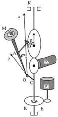
The flat hinges are in joints A,B,O. The rigid joint is in the junction point C. Introduce the notations for the lengths D=OA, h=MA, l=AB=OC, d– radius of the drive shaft. The commutator motors of direct current with indirect excitation are brought in the actuators. The Kirchhoff’s second law for such motors can be written as (1):
Ibdibdt+Rbib+kb1˙b=ebIbdibdt+Rbib+kb1˙b=eb (1)
Ipdipdt+Rpip+kp1B(a,p)˙a=epIpdipdt+Rpip+kp1B(a,p)˙a=ep
Whereepep ,ebeb is voltage ebeb voltage of counter-emf, kb1kb1 , kp1kp1 - coefficient of voltage of counter-emf, k3k3 motor constant IbIb , IpIp - inductance, RbRb , RpRp - resistance. The geometric constraint equation (the distance l between the points A(XA, YA) and B(XB, YB) is constant) is specified as
(XA−XB)2+(YA−YB)2= l2(XA−XB)2+(YA−YB)2= l2 (2)
Ibdibdt+Rbib+kb1˙b=ebIpdipdt+Rpip+kp1B(a,p)˙a=epIbdibdt+Rbib+kb1˙b=ebIpdipdt+Rpip+kp1B(a,p)˙a=ep (3)
(D(cosa−1)+d(1−cosp))2+(Dsina+l−dsinp)2=l2(D(cosa−1)+d(1−cosp))2+(Dsina+l−dsinp)2=l2 (4)
The Lagrange function of the system is
L={m2[l+(D+h)sina]2+Jb2}˙b2+Jp2˙p2+m(D+h)22˙a2−mg(D+h)cosaL={m/2[l+(D+h)sina]2+Jb/2}˙b2+Jp2˙p2+m(D+h)2/2˙a2−mg(D+h)cosa (5)
The system is acted on by the no potential force
˜Qp=−fp˙p+kp2ip;˜Qb=−fb˙b+kb2ib˜Qp=−fp˙p+kp2ip;˜Qb=−fb˙b+kb2ib (6)
Where k2- electromechanical constants of the electric drives, fp ,fb coefficients of rotation resistant. The redundant coordinate velocity can be expressed as a function of all variables and independent velocities after differentiating (5) with respect to time.
˙p=D[dsin(a−p)+(D−d)sina+lcosa]d[Dsin(a−p)+(D−d)sinp+lcosp]˙a=B(a,p)˙a˙p=D[dsin(a−p)+(D−d)sina+lcosa]d[Dsin(a−p)+(D−d)sinp+lcosp]˙a=B(a,p)˙a (7)
If the depended velocities were eliminated taking (7) into consideration, then
L*=12{m[l+(D+h)sina]2+Jb}b2+12{m(D+h)2+JpB2(a,p)}˙a2−mg(D+h)cosaL∗=1/2{m[l+(D+h)sina]2+Jb}b2+1/2{m(D+h)2+JpB2(a,p)}˙a2−mg(D+h)cosa
The prescribed steady motion can be defined by
a−a0=const;˙b=˙b0=consta−a0=const;˙b=˙b0=const (8)
Using systems (3) and (4) it is possible to calculate values of systems at the prescribed steady motion (8): p=p0=const;p=p0=const;
c1sinp0+c2cosp0−c3;c1sinp0+c2cosp0−c3;
c1=dcosa0−d+d2D;c1=dcosa0−d+d2/D;
c3=D+d2D−cosa0(D−d)−d+lsina0;c3=D+d2/D−cosa0(D−d)−d+lsina0;
c2= dsina0+dlD; ib−ib0 = fb˙b0kb2= const;c2= dsina0+dl/D; ib−ib0 = fb˙b0/kb2= const; (9)
ip=ip0=−1B(a0,P0){mg(D+h)sina0+b20m[l+(D+h)sina0](D+h)cosa0}=const;ip=ip0=−1/B(a0,P0){mg(D+h)sina0+b20m[l+(D+h)sina0](D+h)cosa0}=const;
ep=ep0=Rpip0;eb=ebo=Rbibo+kb1˙b0ep=ep0=Rpip0;eb=ebo=Rbibo+kb1˙b0
The next step is analyzing perturbed motion equations in the form (3), Give the coordination:
a=a0+x1; ˙a=x2; ˙b=b0+x3; ib=x4;a=a0+x1; ˙a=x2; ˙b=b0+x3; ib=x4;
ip=ip0+x5;p=p0+x6;ep=ep0+uip=ip0+x5;p=p0+x6;ep=ep0+u
There are two actuators in the considered system and both motors can be enabled. In the system under consideration, only a constant voltage is applied to the motor armature of the actuator P2, at which stationary motion8,9 takes place in the device. The voltage of the counter-emf plays the role of a dissipative force of a special structure11 and has a stabilizing effect. The first approximation is separated and the equations are transformed to the normal form (We pay attention to the terms (∂B∂a)0,(∂B∂p)0(∂B/∂a)0,(∂B/∂p)0 in the expansion of the coefficients in the differentiated geometric constraint):
y1=(x1,x2,x3,x4,x5,z);y1=(x1,x2,x3,x4,x5,z);
˙y=M1y+N1u;˙y=M1y+N1u;
y′=(x1,x2,x3,x4,x5,z);
˙y=M1y+N1u (10)
M1=[010000m1m2m30m4k0m5m6m70000m8m9000m1000m1100B(a0.p0)00000];
N′1=(0,0,0,0,n,0);
w1=m(D+h)2+JpB2(a0,p0);
w2=m[l+(D+h)sina0](D+h)cosa0;
w3=mg(D+h)sina0;
w4=JpB(a0,p0)[(∂B∂a)+B(a0,p0)(∂B∂p)];
w5=m[l+(D+h)sina0]2+Jb
w6=2m[l+(D+h)sina0](D+h);
m1=1w1{b20m[−(D+h)sina0+(D+h)2cos2a0]+mg(D+h)cosa0+kp2ip0(∂B∂a)0};
m2=−B2(a0,p0)fpw1;
m3=2˙b0w2w1;
m4=1w5B(a0,p0)kp2;k=1w5kp2ip0(∂B∂a)0;
m5=1w52˙b0w2;
m6=−fbw5;
m7=kb2w5;
m8=−kb1Ib;
m9=−RbIb;
m10=−kp1B(a0,p0)Ib;
m11=−RpIp;
To determine the variable corresponding to the zero root of the characteristic equation, we use the linear non singular substitution1,2,5,6
x6=z+B(a0,p0)x1 (11)
The matrix M in (10) results the from after (11)
˜M1=[010000˜m1m2m30m4k0m5m6m70000m8m9000m1000m110000000]
˜m1=m1+kB(a0,p0) and the system (11) will take so-called special form of the theory of critical cases.7-8 It gives the possibility to separate controlled subsystem,1,2,6,9 which can be written as
˙x=Mx+Nu;x′=(x1,x2,x3,x4,x5); (12)
M=[01000˜m1m2m30m40m5m6m7000m8m900m1000m11]; N=[n0000].
The controllability condition is satisfied for the system (12);
rank(NMNM2NM3NM4N)=5 .
For the unique determination of the coefficients of the stabilizing control
u=l1x1+l2x2+l3x3+l4x4+l5x5
Optimal criterion is introduced
I=∞∫t0(x21+x22+x23+x24+x25+u2)dt→min
The coefficients of the control laws can be found by solving linear-quadratic problems using N.N. Krasovsky8 method. Computational solution can be found by Repin-Tretyakov8 procedure.
This approach allows stabilizing any steady motion of this manipulator. However, for the manipulator design under consideration it is possible to distinguish stable operating modes even at constant voltages on drive motors. They here play the role of program controls, ensuring the implementation of a given mode of operation. Numerical modeling was carried out in this problem. With the following parameters, the following graphs of transient processes were obtained (Figures 2–11). As follows from these graphs, the system returns to the given motion in over time. At the same time, in Figures 2–6, on which the dynamics are simulated for 50seconds, oscillations near a given operating mode are clearly noticeable, but not all reversible ones show the return of the disturbances to zero. Therefore, for the same initial disturbance, Figures 7–11 show that within 1000seconds the perturbations in all variables have practically returned to zero. Numerical results were obtained with the following parameters: x=[0.01 0 0 0 0] – Initial perturbation D= 0.6; d= 0.2;l=0.3; a=0.1; m=1; g=9.8; h=0.3; Jp=0.5; Jb=0.5; b0=10; k1p=0.2; k2p=0.2; k1b=0.02; k2b=0.02; fp=0.02; fb=0.02; Ib=0.002; Ip=0.002; Rb=10; Rp=10;
In the work the stabilization problem of steady motions for the mechanical systems with the geometrical constraints is investigated. The general method for mathematical modeling of dynamics for these class systems is obtained by the consideration such systems as Holonomic systems with redundant coordinates. The accurate nonlinear mathematical model was constructed, using the motion equations in Shul’gin’s13 form. Using rigorous methods of analytical mechanics,13,23,24 nonlinear stability theory,8–10 Krasovsky7 method and previously obtained results4–6,11,12,22 is developed the procedure for the unique determination of the coefficients of the stabilizing control. For the practical calculation of the coefficients can be applied Repin–Tretyakov procedure.7 The proposed method is used for stabilization problem of steady motion of the manipulator with geometrical constraints. In conclusion, the authors thank Rukavishnikova A.S. for carrying out a computational experiment.
No financial exists.
No conflict of interest exists.
©2017 Krasinkiy, et al. This is an open access article distributed under the terms of the, which permits unrestricted use, distribution, and build upon your work non-commercially.