Dynamic model
The control problem of the crane during the horizontal transportation phase is addressed in this section. The rope has constant length, and the system has two DOFs. The following assumptions are established to obtain the dynamic model of the system:
- the payload is considered a point mass;
- the mass and stiffness of the hoisting rope are neglected;
- the effects of wind disturbances are not considered. Based on the Lagrangian formulation,23 the dynamic model of a 2D overhead crane system is represented by the following:
, (1)
Where denotes the system state vector with as the trolley displacement and as the payload swing angle (Figure 1). ,, and represent the inertia matrix, centripetal-Coriolis matrix, damping matrix, a term derived from potential energy, input control matrix, and force acting on the trolley, respectively. These variables are explicitly defined as follows:
,
, ,
,
whereandrepresent the trolley mass and payload mass, respectively; denotes the length of the rope;is the gravitational acceleration;is the damping coefficient on the trolley,. The forcesummarizes the actuating forces and coulomb forcesas the following:
(2)

Figure 1 Overhead crane model.
The coulomb friction in this study is modeled by the tanh function instead of the sign function:
,
where is the magnitude of the coulomb friction on the trolley.
Eq. (1) can be rewritten as follows:
, (3)
. (4)
By solving from Eq. (4) and integrating this variable into Eq. (3), we obtain the following:
, (5)
, (6)
with
. (7)
The following assumptions are made from the practical application of an overhead crane: i) the cable length is always positive (i.e., ), and ii) the swing angle of the payload during the transportation process always remains in the interval between and , []. The dynamic expression in Eq. (1) has the following important properties: (i) the inertia matrix is positive definite and symmetric, ; (ii) the matrix is skew symmetric, for .
Open-loop system passivity
Consider that the energy-storage functionconsists of the kinetic and potential energies of the system:
, (8)
With
The energy-storage function derivative regarding time is calculated as follows:
(9)
Substituting the term from Eq. (1) and using the skew-symmetric property of produces the following:
(10)
The term denotes the power supplied by the actuators for the trolley. The inequality in Eq. (10) shows that the system is passive. Integrating both sides from zero toyields the following:
or. In case of a zero input, that is, the system will have a stable equilibrium, where the total energy is minimized after taking the zero value.
Energy-based control design
The control design aims to bring the trolley from an initial condition to a desired position while the payload swing angle is suppressed and vanishes completely at the load destination. This objective indicates that the state variables should reach their desired valuesafter a short time. The forceis derived initially by using an energy-based approach. The friction force is then added to obtain the actuating forces from Eq (2):
(11)
Controller design
The passivity property of the system allows us to exploit the energy of the system, or, in the controller design. The following Lyapunov candidate function is proposed:
, (12)
Wherecan take the values of one or two, , and The second and third terms inare considered additional kinetic and potential energies that are related to the motion of the actuated coordinates, respectively. By differentiatingwith respect to time, one obtains the following:
. (13)
By substituting Eq. (10) into Eq. (13) and accounting for Eq. (5), the following is obtained:
(14)
Eq. (14) suggests choosing the following control law:
, (15)
with,
, (16)
. (17)
By defining the controller via Eqs. (15) to (17), the derivativebecomes the following:
. (18)
The variable is independent of, whereas is dependent on not only but also its derivative (Eq. (17)). The parameterappears only in one term in Eq. (15). The system energy appears in the controller (Eq. (15)) only if because leads to .
The parametercan be chosen arbitrarily provided that it is non-negative, thus leading to. The three cases for these choices are as follows:; ; with . The part in Eq. (17) that corresponds with the chosen is expressed as follows:
, (19)
, (20)
. (21)
The term in Eq. (21)s written in detail as follows:
.
The five controllers obtained from Eqs. (15) and (17) by the combination of and the three cases of are presented in the following.
Controller 1. The simplest case is produced by and . For this case, Eq. (15) becomes a proportional-derivative (PD) controller.
. (22)
Controller 2. By choosing , and , one obtains the following:
, (23)
where is defined in Eq. (16), and is defined in Eq. (20).
Controller 3. By choosing , , and ,
, (24)
where is defined in Eq. (16), and is defined in Eq. (20).
Controller 4. By choosing and ,
, (25)
where is defined in Eq. (16), and is defined in Eq. (21).
Controller 5. By choosing and ,
, (26)
where is defined in Eq. (16), and is defined in Eq. (21).
Remarks:
1) The controller in Eq. (22) is the simplest and does not require the swing angle and swing angle derivative for feedback. Other controllers require swing-angle sensors.
2) The controllers in Eqs. (24) and (26) require a longer time than the controllers in Eqs. (23) and (25) in calculating the total energy E of the system.
3) The term can be chosen as a function of provided that is positive and definite. For example, in the case of the PD controller, one can write the following:
. (27)
4) All five controllers can be extended and applied to overhead cranes with three, four, or five DOFs.
Stability analysis
Theorem 1. The system in Eq. (1) with one of the controllers from Eqs. (22) to (26) are asymptotically stable at the equilibrium point:
. (28)
Proof. The stability analysis of all five controllers is almost similar; thus, only the stability of the controller in Eq. (25) is proven. The proof of the stability of the equilibrium point or the desired position is based on LaSalle invariance theorem (e.g., see24). From Eq. (18), the invariant set W can be defined as follows:
. [in W].
This expression denotes that, can take any values, the constant in W is the equilibrium point, and. The proof is obtained by contradiction. Assuming that, that is, these variables have constant values that are different from the equilibrium, and by considering the control law in Eq. (25), the following expression is obtained:
. (29)
Eq. (5) with deduces the condition for as :
After simplifying the aforementioned equation, we obtain the following:
. (30)
From Eq. (6), we obtain the following in W:
. (31)
From Eq. (31), if or , then in W yields the following;
. (32)
1) If , then from Eq. (30) causes from Eq. (29).
2) If , taking from Eq. (32) then placing it into Eq. (30) obtains the following:
,
or
. (33)
From (33), . This constant must be zero because leads to in Eq. (31). This case leads to. However, leads to ; hence, the assumption that is invalid. Based on the previous analysis, the largest invariant set W includes only the equilibrium point of
.
We conclude that the system states asymptotically converge to the desired values by invoking LaSalle invariance theorem.24
Numerical simulations and experiments
Numerical simulations are conducted by using MATLAB software to verify the validity and efficiency of the five controllers. Experiments are also conducted by using an overhead crane test bed to validate the control approach. The control objective of the overhead crane is to move the trolley to its destination while complementing the load anti-swing.
Numerical simulations
In the simulation, the system parameters are set as follows: , , Ns/m, m, and . The target position of the trolley is set as m. The controllers in Eqs. (22) to (26) are implemented in the simulation. The parameters of these controllers are chosen as follows:
, , , .
In the simulations, the fourth-order Runge–Kutta method with a time step of 0.01s is applied. The simulation results for the trolley displacement, load swing angle, and control input are shown in Figure 2-4. The simulation results show that the energy control scheme controls the trolley to reach the desired destination while implementing anti-sway control. In all cases, the desired positions of the trolley and payload are reached after approximately 15s to 18s. During this time, the payload swing angle increases from zero at the starting time and damped oscillation. The maximum swing angle is approximately 4°. In addition to the maximum swing angle, the settling time maximum control forces, and “energy consumption” (defined by ) are considered in comparing controller performances. The performance indices of each case are presented in Table 1.

Figure 2 Trolley displacements.
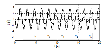
Figure 3 Cable swing angle.

Figure 4 Trolley moving force.
Controller |
|
|
|
|
1. (22) |
3.47 |
15 |
10 |
29.05 |
2. (23) |
2.38 |
19 |
4.21 |
22.88 |
3. (24) |
3.32 |
16 |
7.01 |
28.26 |
4.(25) |
2.62 |
19 |
5 |
24.13 |
5.(26) |
3.8 |
15 |
10 |
31.32 |
Table 1 Performance indices of the controllers
Remarks:
- The swing angle caused by the controllers in Eqs. (24) and (26) are relatively larger than that by other cases. The swing angle decreases slowly. These two controllers are derived from the square of the system energy, whereas the controllers in Eqs. (22), (23), and (25) are derived from. The swing angles by the controllers derived from decrease significantly faster than those by controllers derived from.
- Table 1 shows that the swing angle and energy consumption of the controllers in Eqs. (23) and (25) are smaller than those of other controllers. However, the settling time of the trolley from the controllers in Eqs. (23) and (25) is longer than that from other controllers.
- The simulation results show that the trolley position is reached. However, the swing angle is still vibrating and decreasing slowly.
- The choice of control parameters, namely, and, is an ad hoc problem. The choice of optimal parameters for the controllers is not addressed in this paper.
The controllers based on the energy approach guarantees that the system reaches the desired position. However, choosing the control parameters is not easy, and the swing angle is still large when the trolley reaches its desired position. To overcome this difficulty, a linear state feedback controller is applied in conjunction with the controllers in Eq. (15). The linear state feedback controller is designed based on the linearized model of the system around the desired position. The linearized model is determined to be controllable. Thus, the pole placement technique or linear quadratic regulator (LQR) can be applied to determine the feedback gain matrix, K.25 The command control is then defined as follows:
(34)
Where .
The linearized model around the desired position is given as follows:
Matrices and are chosen to obtain the feedback gain:
,
The matrix K is given by the LQR command in MATLAB as the following:
.
The aforementioned nonlinear controllers in Eqs. (22) to (26) guarantee the stability of the desired position; thus, the state variable and are small around the end position. Therefore, the stability of the closed-loop system is still guaranteed by switching from the nonlinear controllers to the LQR controller in Eq. (34). In the following simulation, the LQR controller is switched on when the trolley reaches 80% of its path. The simulation results by the combination of nonlinear (25) [] and linear controllers (34) [], as well as (26) [] and (34) [], are shown in Figure 5-7. Figure 5 shows that the time history of the trolley displacement is not changed significantly after switching to linear control. The advantage of switching to the linear controller is clearly shown by comparing Figure 6 & 3. The swing angle after switching time converges to zero in a short period.

Figure 5 Trolley displacement.
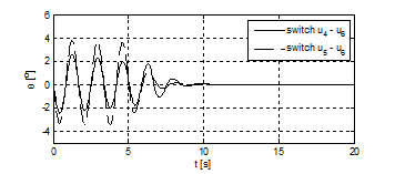
Figure 6 Cable swing angle.

Figure 7 Force on the trolley.
Experiments
The controllers given by Eqs. (25) & (26) combined with Eq. (34) are implemented on the laboratory crane (Figure 8). The trolley is driven by a direct current (DC) motor, and incremental encoders with 1024 counts per revolution are used to measure the trolley displacements and payload swing angle. The crane system is connected to a target personal computer (PC) with two interfaced cards. An NI PCI-6602 card is used to send pulse-width modulation signals to the amplifiers of the DC motor and acquire signals from the encoders. An NI PCI-6025E multifunction card is used to transfer the direction control signals to the motor amplifiers. The target PC is connected to a host PC through RS-232 ports. The overhead crane is controlled by the host PC, which integrates the presented controller designs based on MATLAB/SIMULINK with xPC target solution.
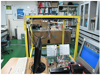
Figure 8 Laboratory overhead crane systems.
The parameters of the laboratory crane are as follows: , , 0.7 m, and . The target position of the trolley is set as m. The parameters of the controllers are chosen as follows:
, , , .
The experimental results are presented in Figure 9-11. The trolley reaches the set position after approximately 8s. The swing angle achieves the maximum value of approximately 5° and 10° by the controllers in Eqs. (25) and (26), respectively. The simulation and experimental results show that the controllers derived fromachieves better performances than the controllers derived fromin terms of maximum swing and maximum driving forces. Moreover, system stability is not affected by switching to the LQR controller.

Figure 9 Trolley displacement.
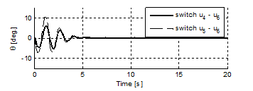
Figure 10 Cable swing angle.
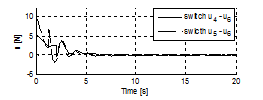
Figure 11 Force on the trolley.


