eISSN: 2574-8092


Research Article Volume 11 Issue 3
 Paulo Bueno Santos, Marcelo Campos Rebouças, Julio Cesar de Almeida Freitas, Rogério Adas Pereira Vitalli
Department of Robotics Engineering, Robotics Advanced Institute (IAR), Brazil
Correspondence: Edson Amado da Silva Junior, Department of Robotics Engineering, Robotics Advanced Institute (IAR), Brazil
Received: September 05, 2025 | Published: October 13, 2025
Citation: Junior EAS, Santos PB, Rebouças MC, et al. A comparative analysis between an industrial vision system and an open-source solution for vision-guided robotics (VGR). Int Rob Auto J. 2025;11(2):82-86. DOI: 10.15406/iratj.2025.11.00304
This work performs a comparative evaluation between an industrial vision system (Cognex) and a low-cost solution (Webcam/OpenCV) for a vision-guided robotics task, analyzing accuracy, repeatability, and robustness. The results demonstrate that, although the Cognex system exhibits higher numerical accuracy and repeatability under ideal conditions, the solution with Webcam/ArUco shows greater robustness to variations in illumination. Crucially, both systems proved to be functionally viable, allowing the robot to correctly grip the part in all trials. It is concluded that the choice of technology involves a trade-off between the numerical precision of the industrial solution and the robustness and low cost of the open-source alternative, with "sufficient accuracy" being a determining criterion for the application's viability.
Keywords: vision-guided robotics (VGR), cognex camera, openCV, ArUco, Kuka
CCD, charge-coupled device; PLC(s), programmable logic controllers; CMOS, complementary metal-oxide-semiconductor; EMA, exponential moving average; HD, High Definition; IP, internet protocol; ISM, in-sight micro; PC, personal computer; TCP, Transmission Control Protocol; USB, universal serial bus; VGR, vision-guided robotics
Vision-Guided Robotics (VGR) has established itself as one of the key technologies of Industry 4.0, enabling robots to perform manipulation, assembly, and inspection tasks in dynamic environments without the need for fixed fixtures. This approach enhances the flexibility of production systems by allowing the robot to adjust its trajectory based on real-time visual information, integrating perception and control within the same operational cycle.1
In the industrial context, proprietary solutions, such as Cognex cameras, offer direct integration with programmable logic controllers (PLCs), advanced image processing tools, and high reliability. However, such systems come with high costs of acquisition, maintenance, and updates. On the other hand, alternatives based on affordable hardware and open-source libraries, such as OpenCV combined with ArUco markers, have attracted growing interest in both academic and industrial settings for their combination of flexibility, low cost, and scalability.2,3 Furthermore, recent studies have compared vision tools and architectures in real-world scenarios—for example, performance analyses of measurement tools in the Cognex D900 system and evaluations of different vision systems applied to collaborative robotics—reinforcing the need for practical and quantitative comparisons like the one proposed in this work.4,5
Despite advances, technical challenges in VGR persist, such as hand-eye calibration, variations in illumination, processing latency, and robustness under adverse conditions.6 Moreover, the literature still lacks comparative studies that quantitatively evaluate, on the same real industrial robot setup, the performance differences between proprietary systems and low-cost solutions. This gap is particularly relevant in the context of digital twins and virtual commissioning, where the calibration of vision systems and their integration with robotic manipulators represent critical steps for the reliability of the virtual model.7,8
Given this scenario, the present work proposes a comparative evaluation between two vision systems applied to vision-guided robotics: (i) a Cognex ISM-1400 industrial camera, integrated with a KUKA KR6 R900 sixx robot via a Siemens S7-1200 PLC, and (ii) a Logitech C920 webcam with OpenCV/ArUco support, equally calibrated and integrated with the same robot. The objective is to analyze the accuracy, repeatability, and robustness to illumination of both systems, highlighting their potentials and limitations, and contributing to the discussion on the use of proprietary solutions versus open-source alternatives in academic and industrial applications.
The experimental setup was assembled on a test bench equipped with a KUKA KR6 R900 sixx industrial robot, as can be seen in Figure 1. This six-degree-of-freedom manipulator has a maximum reach of 901 mm, a nominal payload of 6 kg, and a repeatability of ±0.03 mm, according to the manufacturer's technical specifications.9 The robot was coupled with a Schunk PGN+125-1 pneumatic gripper, characterized by its robustness, adjustable gripping force, and a stroke of up to 25 mm, suitable for clamping blocks and metal parts in industrial environments. The test bench was configured to simulate real operating conditions, including the robot's positioning on a rigid metal base, with auxiliary position sensors and a pneumatic supply for gripper actuation. The communication of the robot controller (KRC4 compact) was established via a Profinet network, ensuring low latency and high reliability in data exchange with the programmable logic controller (PLC). The PLC used was a Siemens S7-1200, model 1212C, chosen for its native Profinet compatibility, which dispenses with additional modules and ensures direct integration with the robotic cell.
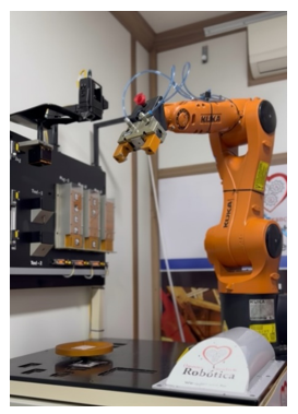
Figure 1 Experimental robotic cell for VGR tests. The KUKA KR6 R900 sixx robot, equipped with a pneumatic gripper, validates the camera's coordinates by manipulating the target block.
Two distinct vision systems were employed for the comparison.
Cognex In-Sight Micro 1400 (ISM-1400) industrial camera: Configured in the In-Sight Explorer software, with direct communication to the Siemens S7-1200 PLC via Profinet, as shown in Figure 2. This integration setup between a KUKA robot and a Cognex camera has been explored in previous works, validating its feasibility in industrial robotic cells.10
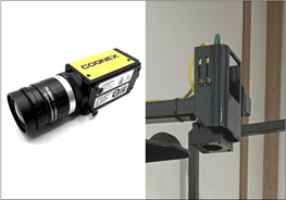
Figure 2 Cognex ISM-1400 industrial camera, configured to detect the target block through native edge and contrast analysis.
Logitech C920 Full HD webcam: The low-cost, open-source vision approach was implemented with a Logitech C920 Full HD webcam, Figure 3. A custom Python script, using the OpenCV library, was developed for the detection of ArUco fiducial markers affixed to the object. From the identification of the markers, the script estimated the object's position and orientation, calculated its coordinates in the workspace, and transmitted them to the PLC for the subsequent robot movement.
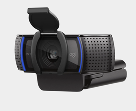
Figure 3 Logitech C920 webcam, used as the low-cost vision system for ArUco marker detection.
Both systems underwent intrinsic calibration using a printed checkerboard pattern. This procedure is widely recognized in the literature as a reliable method for estimating a camera's internal parameters, such as focal length and radial and tangential distortion coefficients. Recent studies consolidate the use of the checkerboard pattern, both in calibration with multiple boards in a single capture11 and in robust corner detection techniques using deep learning approaches.12
Once intrinsic calibration was completed, extrinsic (hand-eye) calibration was performed to establish the correspondence between the camera and robot coordinate systems. The approach consisted of defining a user frame in the robot with a known origin (0,0). The coordinates of this same origin point, when measured by the vision system, provided the translation (ΔX, ΔY) and rotation (Δθ) values necessary for correction. These values were applied as offsets to all subsequent measurements to ensure that the camera's coordinates were correctly mapped to the robot's reference frame. The precision of this mapping is critical, and the literature reinforces that the quality of hand-eye calibration is a determining factor for the success of VGR applications.6
The experimental procedure was conducted in 5 main steps:
Cognex camera calibration: The intrinsic calibration of the Cognex In-Sight Micro 1400 was performed in the In-Sight Explorer 6.5.1 software using a 24 x 14 checkerboard pattern with 10 mm spacing and the Grid method. This process allowed for the estimation of the camera's internal parameters, ensuring the reliability of the measurements. The process involved selecting the calibration type as Grid, the initial setup, and the automatic detection of reference points on the checkerboard pattern, as can be seen in Figure 4.
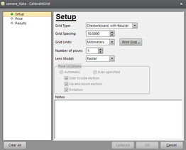
Figure 4 In-Sight Explorer software interface during Grid Calibration.
After the initial settings, the software automatically detects the checkerboard pattern by recognizing the intersections between the white and black squares, as illustrated in Figure 5. Next, the evaluation of the obtained intrinsic calibration is performed. For this analysis, a dimensionless scale from 0 to 5 is used, where values close to 0 indicate excellent calibration, while values close to 5 represent poor calibration. The obtained results are presented in Figure 6, showing a final value of 0.108, classified as excellent. Furthermore, an average error of 0.108 px and a maximum error of 0.287 px were observed, confirming the precision of the calibration process.
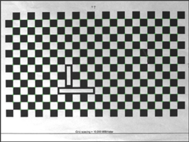
Figure 5 Automatic detection of the checkerboard pattern by the calibration software.
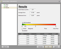
Figure 6 Calibration results in the In-Sight Explorer software, indicating an average error of 0.108.
Logitech C920 webcam calibration: The intrinsic calibration of the Logitech C920 webcam was performed via a Python script using the OpenCV library, employing an 8 × 6 intersection checkerboard pattern with 35 mm squares, which can be seen in Figure 7. To improve edge definition, a sharpen filter was applied during processing. Considering a magnification factor of 2.5, the procedure resulted in an average of 2.026 px/mm and an Exponential Moving Average (EMA) smoothed value of 2.022 px/mm; the data found during calibration can be verified in Figure 8. These values correspond to approximately 0.495 mm/px, ensuring consistency in the pixel-to-millimeter conversion and reinforcing the reliability of subsequent tests.
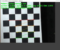
Figure 7 Checkerboard pattern (7 × 5, 35 mm squares) used in the intrinsic calibration process of the Logitech C920 webcam.
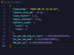
Figure 8 Calibration result for the Logitech C920 webcam, showing a scale of 2.026 px/mm (average value) and 2.022 px/mm (EMA smoothed value), corresponding to approximately 0.495 mm/px.
Camera-robot reference frame integration and coordinate calculation for Cognex camera: After intrinsic calibrations, extrinsic calibration was performed to align the reference frames. The run-time calculation process begins with the acquisition of an image, in which the vision system simultaneously detects the position of the reference point (the user frame origin) and the position of the target block, as illustrated in Figure 9. From these two raw measurements, the final coordinate mapping is performed through a two-step process:
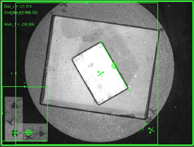
Figure 9 Detection of the user frame origin (reference) and the target block by the vision interface, providing the raw coordinates for the final position calculation. Step 1: Systematic Calibration by Change of Reference Frame.
First, the main mathematical relationship was established. This step consists of (a) calculating the block's position relative to the robot's origin through the correct vector difference (P_block - P_origin), (b) applying a sign inversion to the X-axis result to compensate for the opposite axis orientations between the camera (X positive to the left) and the robot (X positive to the right), and (c) calculating the relative orientation of the block by subtracting the measured orientation of the origin.
Step 2: Empirical fine-tuning and final control logic
After applying the systematic calibration, it was necessary to implement empirical adjustments and safety logic to ensure the system's precision and integrity. This process was divided to handle position and orientation.
Final position calculation (X, Y)
A small, constant residual positioning error was observed. To correct this deviation, an empirical fine-tuning vector was determined through physical measurement of the discrepancy. This correction vector, with values of (C_X = +7.3 mm, C_Y = +4.2 mm), was then added to the result of the first step, according to the final formula:
Final orientation calculation (θ) and collision prevention
For the angle, the logic implemented in the PLC included not only an empirical angular adjustment (Cθ) but also a safety validation. The process consists of:
Camera-robot reference frame integration and coordinate calculation for webcam
For the webcam-based system, the Python/OpenCV script implemented a coordinate calculation algorithm reflecting a two-step calibration. The camera's axis convention was defined with the X-axis positive in the vertical direction (down) and the Y-axis positive in the horizontal direction (right), with the reference frame origin fixed at the pixel point (92, 25). The final coordinates sent to the robot were obtained through the following equations:
where (CYbloco ,CXbloco) are the marker's centroid coordinates in pixels, (Oy ,Ox) are the origin point's coordinates in pixels, Smm/px is the scale factor, and (CX, CY) are the empirical fine-tuning vector constants (+3.15 mm and -5.15 mm, respectively).
Final orientation calculation (θ) and collision prevention for the webcam:
Where, θraw is the raw angle extracted from the ArUco marker, -90° is a base rotation for axis alignment, and Cθ is the empirical angular adjustment constant (+72.5°). This combined process ensures that each camera measurement is systematically corrected before being sent to the PLC. Figure 10 shows the detection of the block with the ArUco marker.
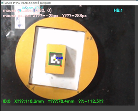
Figure 10 Interface of the vision script for the webcam, illustrating the real-time detection of an ArUco marker (ID=0). The system overlays the marker's contour and displays the final coordinates (X, Y) in millimeters and the orientation (θ) in degrees at the bottom.
Data collection and reference definition
For data collection, the test block was positioned at different locations on the bench. At each position, the coordinates were first recorded by the vision system under test. Then, to obtain the ground truth value, the robot was operated in manual mode, and its end-effector was moved with precision until the gripper was perfectly aligned to grip the block. The robot's exact position, read directly from its controller, was then recorded as the real coordinate. To isolate the planar orientation analysis, the B and C axes of the gripper were kept fixed, allowing only the A-axis (rotation in the plane) to vary, corresponding to the θ measurement (Table 1).
|
Characteristic |
Cognex ISM 1400 |
Webcam Logitech C920 |
|
Type |
Industrial camera |
General-purpose USB camera |
|
Sensor / Resolution |
Charge-Coupled Device (CCD), 640 × 480 px |
Complementary Metal-Oxide-Semiconductor (CMOS), 1920 × 1080 px (Full HD) |
|
Optics |
Interchangeable C-Mount lenses |
Integrated fixed lens (autofocus) |
|
Image Processing |
Embedded (In-Sight Explorer) |
Requires external PC (Python/OpenCV) |
|
Illumination |
Integrated illumination with intensity control. |
No built-in illumination for industrial use |
|
Communication |
Industrial Ethernet (Profinet, EtherNet/IP, Modbus TCP) |
USB 2.0 |
|
Cost |
High > $3500 USD |
Low ~ $150 USD |
Table 1 Presents a comparison between the two cameras in terms of hardware specifications, highlighting the differences in resolution, optics, processing method, and cost
Comparative analysis of the characteristics of the industrial vision solution (Cognex ISM-1400) and the low-cost solution (Logitech C920) used in the study.
The presentation of the quantitative results begins with the validation of the calibration processes. The intrinsic calibration of the Cognex camera resulted in an average reprojection error of 0.108 pixels, classified by the software as "Excellent." For the Logitech C920 webcam, the procedure determined an average scale factor of 2.026 px/mm, used for the metric conversion of measurements. With the systems duly calibrated, the comparative performance was evaluated. Table 2 presents the detailed statistical analysis of the measurement errors for both systems, measured under ideal lighting conditions. The data quantitatively demonstrate the superior performance of the Cognex system across all metrics. The average error of the industrial camera was consistently lower, as observed in the X-axis (1.13 mm vs. 2.22 mm for the webcam). Additionally, the repeatability of the Cognex system was superior, indicated by a lower standard deviation (0.14 mm in X vs. 0.28 mm for the webcam). The analysis of the minimum and maximum values further reveals a smaller error range for the industrial camera, with error peaks reaching 1.33 mm in X, while the webcam reached errors of up to 2.77 mm. Beyond the statistical analysis, the robustness of the systems to variations in luminosity was evaluated. Under low illumination, the Cognex system, which relies on edge and contrast analysis, experienced detection failures, failing to consistently identify the target block. In contrast, the webcam/OpenCV system, based on the detection of the high-contrast pattern of the ArUco marker, demonstrated greater robustness, maintaining the ability to provide the object's coordinates. With the application of supplemental illumination, both systems operated successfully. Finally, a functional validation test demonstrated that, despite the numerical accuracy differences, the coordinates from both the Cognex and the Webcam allowed the robot to successfully and correctly grip the part in all attempts, confirming the functional viability of both approaches for the proposed task.
|
Metric |
Mean |
Standard Deviation |
Minimum |
Maximum |
|
Cognex X (mm) |
1.13 |
0.14 |
0.77 |
1.33 |
|
Cognex Y (mm) |
1.89 |
0.20 |
1.47 |
2.36 |
|
Cognex θ (°) |
1.50 |
0.16 |
1.21 |
1.84 |
|
Webcam X (mm) |
2.22 |
0.28 |
1.52 |
2.77 |
|
Webcam Y (mm) |
2.80 |
0.22 |
2.49 |
3.30 |
|
Webcam θ (°) |
2.87 |
0.30 |
2.17 |
3.57 |
Table 2 Statistical analysis of the measurement errors for the Cognex and Webcam, presenting the mean, standard deviation, and minimum and maximum errors under ideal illumination
The results reveal a fundamental balance between the numerical accuracy of the industrial solution and the robustness of the low-cost alternative. The superiority of the Cognex camera in accuracy and repeatability under ideal conditions (Table 2) can be attributed to its proprietary algorithms optimized for edge and contrast analysis. However, its failure in low illumination exposes a critical dependency on the scene's conditions, a vulnerability that the webcam/ArUco system overcame due to the intrinsic high-contrast nature of its markers. The most pragmatic finding, however, is that of the functional validation, where both systems ensured the correct gripping of the part. This was possible due to the extrinsic calibration, which, through the application of empirical offsets, compensated for mechanical misalignments and validated the webcam for the task, reinforcing the importance of a precise mapping between reference frames, as highlighted in the literature. It is concluded, therefore, that the choice of VGR technology should not be based solely on maximum precision, but rather on a balance between cost, environmental robustness, and the functional requirements of the application.
This work comparatively evaluated an industrial vision system (Cognex) and a low-cost alternative (Webcam/OpenCV) for a VGR task. The numerical superiority of the industrial solution in accuracy was confirmed, but also the greater robustness of the open-source alternative to variations in illumination. The main contribution of this study is the empirical demonstration that, for the proposed manipulation task, the "sufficient accuracy" that guarantees functional viability is a more relevant design criterion than the pursuit of maximum precision. This finding validates the use of more accessible VGR solutions in industrial and academic contexts where functionality prevails over nanometric tolerance.
The authors would like to thank the Advanced Institute of Robotics – IAR for the support provided during the development of this work. They also extend their gratitude to their colleagues who assisted in the tests and practical validation of the robotic cell.
The authors declare that there are no conflicts of interest related to the publication of this research.

©2025 Junior, et al. This is an open access article distributed under the terms of the, which permits unrestricted use, distribution, and build upon your work non-commercially.