Journal of
eISSN: 2574-8114


Research Article Volume 1 Issue 4
1Minjiang University, China
2Jiangnan University, China
Correspondence: Yonggui Li, Fujian Engineering Research Center for Textile and Clothing, Minjiang University, Fuzhou, Fujian, 350108, China, Tel 8659183761611
Received: March 27, 2017 | Published: April 17, 2017
Citation: Li Y, Wei M, Ke H. Numerical simulation analysis of influence of jet orifice structure on fluid field in yarn suction gun for fully drawn yarn. J Textile Eng Fashion Techno. 2017;1(4):135-139. DOI: 10.15406/jteft.2017.01.00024
Software CFX 12.1 was employed to conduct simulation of the fluid field inside yarn suction guns that possess different jet orifice structures and the relation between fluid field distribution and yarn suction performance was analyzed. The effect mechanism of jet orifice structure on properties of yarn suction gun was clarified, achieving reasonable structural parameters: orifice number N was 3, orifice diameter d was 2.0mm, and orifice angle was 75˚. The results indicated that increment of jet orifice number led to the increase of free diffusion of ejected airflow and enhancement of directivity, meanwhile, the air density near tube wall inside the gun and the circumferential velocity component of air were improved, thereby the yarn suction force was increased. The conflict among ejected airflows was increased by the superabundant jet orifice number, leading to the decreased yarn suction force. Reasonable orifice diameter was beneficial to the formation of strong swirling flow, and can prevent the occurrence of normal shock, resulting in the increased yarn suction force. The angle of jet orifice mainly controlled the circumferential velocity component value of air that causing the change of swirling flow strength thus changed the yarn suction force. The yarn suction efficiency was closely relative to the distribution of airflow; especially the influence of the circumferential velocity component of air was the most significant. The occurrence of normal shock was not beneficial to the enhancement of yarn suction force, which should be avoided as much as possible.
Keywords: yarn suction gun, nozzle, airflow, numerical simulation, spinning process, spinning efficiency, fluid dynamics software, geometrical parameters, yarn inhalation tube, jet orifices, gas path, ambient atmosphere, velocity vector, axial component, swirling flow
The yarn suction speed of traditional yarn suction gun, whose impetus is based on compressed air 1−3 or high pressure water,4,5 does not exceed 6000m/min. During the ultra high-speed (winding speed is 6000-12000m/min) spinning process, the only method is to reduce the winding speed to conduct string-ups or spooling, and then back to normal speed, which reduces the spinning efficiency and affects the quality of filaments. Thus, it is eager to exploit novel ultra high-speed yarn suction guns.
In order to provide technical support for preparing high-performance yarn suction guns with strong yarn suction and low-energy consumption, Iemoto and Li etc. systematically studied the influence of the main structural parameters of FDY yarn suction gun on yarn suction efficiency,6 flow field7,8 and the yarn movement.9,10 Li etc. further designed the structure of yarn suction gun11−13 achieving more reasonable nozzle structure.12 However, the mechanism of the effect of jet orifice structure parameters in nozzles on the properties of yarn suction guns is still not clarified. In this work, computational fluid dynamics software CFX 12.1 was employed to conduct numerical simulation for the flow field inside yarn suction guns with different geometrical parameters of the jet orifice. Through analyzing the relationship between flow field distribution and yarn suction properties, the mechanism of the effect of geometrical parameters of the jet orifice on the properties of yarn suction guns was clarified, which offered theoretical basis for further improving the properties of yarn suction guns.
Structure of yarn suction gun and structural parameters of jet orifice
Figure 1 shows the structural representation of the yarn suction gun used in this work. Compressed air entered the yarn suction gun and jets from the jet orifices to the yarn channel of the nozzle ②. The axes of the jet orifices had the circumferential and axial components of the yarn channel of the nozzle. The compressed air issued from the jet orifices expanded, passed spirally through the yarn propulsion tube, which was composed of de Laval tube ③ and straight tube ④, and flowed out from the exit of the yarn suction gun. The running yarn sucked from the entrance of yarn inhalation tube ① was given high propulsion in the yarn propulsion tube by the air issued from the jet orifices and blown out from the exit of the air suction gun together with the compressed-air(Table 1).6
Parameter |
value |
Jet orifice number N |
1、2、3、4、5 |
Orifice diameter d / mm |
1.6、1.8、 2.0、2.2、2.4 |
Orifice angle ø/ ˚ |
50、60、70、75、80 |
Table 1 Structural parameters of jet orifice
Because the diameter of yarn is much less than that of yarn path, which produces negligible effect on fluid field, numerical simulation was conducted in the case that assuming there is no yarn in gas path, simplifying computational process. Figure 2 shows the three-dimensional computational domain of yarn suction gun. Because 0.6MPa (absolute pressure, the following contents all using absolute pressure) of supply pressure was employed in literature,12 to facilitate comparison, the supply pressure of compressed air and the kelvin temperature in this work are P0=0.6013MPa and T0=293K, respectively.
Due to relatively small jet orifice diameter, supercritical state will be achieved in jet orifice,14 so critical condition was adopted as boundary condition of spray orifice entrance. The ambient atmosphere, i.e. atmospheric pressure Pa=0.1013 MPa and absolute temperature Ta=293K. Air was assumed to be viscoelastic ideal gas. Three-dimensional unsteady compressible Navier-Stokes equation was chosen as the governing equation, k-e model was chosen as turbulence model. Air was high-speed running in yarn suction gun, hardly conducting heat exchange with environment. Thus, this airflow was assumed to be adiabatic flow. Calculating and simulating the fluid distribution using this method possess superior accuracy, and the simulation results were basically consistent with experimental result.7−8
Software CFX 12.1 was employed to conduct numerical simulation in this work. The used computer was Dell T5500 (two CPU (Intel & Xeon E5630, 2.53 GHz); RAM (12.0 GB). For instance, for yarn suction gun (N=3, d=2.0mm, ø=75˚), the grid number was 9685143, needing 8 hours to complete calculation.
Effect of jet orifice number N on the fluid field of yarn suction gun
To compare the effect of different orifice numbers on yarn suction strength, under the condition of guarantee that keeping air intake area (12.56 mm2) stable, we changed N and d, set ø=75˚.
Figure 3 shows the Laval tube inside the yarn suction gun with different jet orifice number N and the contours of air density r and air velocity v on xz plane. As shown in Figure 3, when N=1, the distribution of r and v is quite disordered, no distinct high-density and high-speed area were formed near the tube wall of Laval tube, and no vacuum space was formed near the center axis of the Laval tube. Especially, this phenomenon was more obvious in the upstream region of Laval tube, which does not keep characteristics of high-speed swirling flow. So, when N=1, there was no strong swirling flow occurring inside yarn suction gun. Due to space limitations, the velocity vector distribution was not displayed in this paper. When N=1, air was ejected from jet orifices, quickly expanding and diffusing to around, which led to airflow disorder inside nozzles, and the direction of the airflow became unstable, strong swirling flow cannot be achieved. Hence, when N=1, the swirling flow was very weak, the zone of negative pressure inside Laval tube was small, which cannot produced enough suction force. This is the main reason why the yarn suction gun cannot achieve suction of yarn reported in literature.12

(a) Density ρ (b) Velocity v
As shown in Figure 3, when N£3, the vacuum region near the throat of Laval tube was increasing as N increased, and the airflow was also gradually concentrated to the tube wall, forming high-density and high-speed airflow layer. Moreover, the r and v were gradually increasing, i.e. the vortex intensity was gradually increasing. When N³3, with the increment of N, slight decline happened in the upstream high-speed zone of Laval tube, i.e. the vortex intensity reduced slightly. Through analyzing the airflow velocity vector diagram near the exit of jet orifice which was not given in this paper, we can find the following phenomenon happened. As N increased, d decreased, the diffusion caused by expansion of airflow sprayed from jet orifices was decreased, and the directivity of airflow was enhanced; In addition, because the mutual restriction of sprayed few strands of airflow was increased, the directivity of airflow also kept well; making the formed vortex intensity enlarged finally. However, when the spray orifice number was superabundant (e.g. N>3), the mutual conflict of sprayed airflow was enlarged, and the kinetic energy loss was increased, which led to decrease of airflow velocity and vortex intensity. This may be one of main reasons why the yarn suction force F was highest when N=3.12
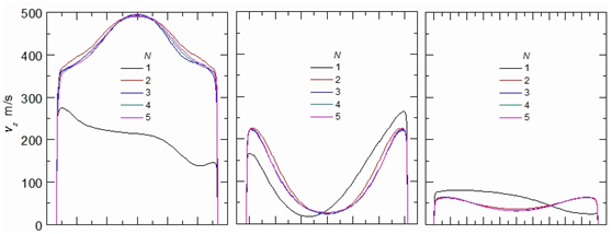
Figure 4 shows radial velocity distributions of axial component vz and circumferential component vc of airflow velocity in throat of yarn suction gun with different N, middle of Laval tube and straight tube. Radial component of airflow velocity was very small in comparison with vz and vc, which can be ignored, so it was not discussed in this paper. When N=1, vz in throat part was slow see Figure 4(a) & (d) and the distribution was disordered although vc near tube wall was superior, while it did not possess characteristics of high-speed swirling flow; in the straight tube, the swirling flow became very weak see Figure 4(c) & (f).


As shown in Figure 4, when N³2, vz and vc near tube wall of Laval tube and straight tube were all much larger than those in center part, so the stronger swirling flow was formed. The influence of N on vz was much less than that on vc, which even can be neglected. Hence, the yarn suction properties of yarn suction gun were more depended on vc rather than vz. Near the tube wall, as N increased, vc increased at first then decreased, reached to the largest value when N=3. In straight tube, the distribution of vz and vc was almost not affected by N see Figure 4(c) & (f).
The suction force of yarn suction gun F to yarn can be calculated by the following equation:7
Cf is frictional resistance coefficient; r is air density; v’ is airflow velocity; v is yarn speed; d is yarn diameter; L is the length of yarn in airflow. Thus, when v’ maintains stable, F is affected by v, r and L. F is easier affected by v rather than by r.
Along with the increase of N, strong swirling flow was formed in yarn suction gun, most airflow conducted spiral movement along with tube wall of yarn promotion tube, forming high-speed and high-density district. High-speed rotation of airflow led to that the sucked yarn moved in high-speed swirl along with tube wall. When N=3, F was improved by relatively high v and p districts Figure 3 near the tube wall. In the state of helical motion, the contact area between yarn and air was much larger than that in the state of rectilinear motion. Significant increase of L was caused by the helical motion of airflow, as can be seen from the equation, the greater L, the greater F. L was mainly decided by vc. As vc increased, screw pitch of yarn in helical motion was reduced, L was enlarged. Near the tube wall, vc reached to the largest value when N=3, this is one of the main reasons why F achieved the largest value when N=3.12
In conclusion, according to the simulation and experimental results, jet orifice number N=3 was reasonable; simulation results were consistent with experimental results (experimental methods and results see literature),12 can be used to explain the yarn suction mechanism of yarn suction gun; Through controlling the diffusion and directivity of ejected airflow, variation of N caused the variation of r and vc, further affecting F.
Influence of jet orifice diameter on the flow field
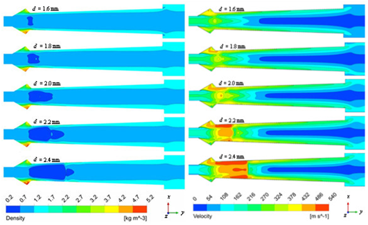
Figure 5 is the contours of air density ρ and air velocity v at different d (N=3,ø=75˚). As shown in Figure 5, the vacuum region near Laval tube throat and supersonic region near pile wall gradually enlarged with the increment of d. v was increased as well, namely the vortex intensity was gradually improved. This was because that the air flow increased with the increment of d. Thus, v was increased according to the law of conservation of mass. Normal shock wave occurred up the Laval tube when d≥2.2 mm, and transferred to the downstream with the increment of d. The occurrence of normal shock wave made parts of kinetic energy converted into heat energy,14 which had no action on yarn suction.

(a) Density ρ (b) Velocity v
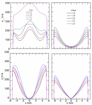
Figure 6 is the radial distributions of vz and vc at different d (N=3, ø=75˚). As shown inFigure 6, the vz and vc near the pipe wall increased with the increment of d. Theoretically, high speed high density area Figure 5 and vc Figure 6 evidently enlarged with the increment of d, which will lead to increase of F. However, F increased at first then decreased with the increment of d, and reached the peak value when d=2.2mm. The yarn suction efficiency (ratio of F to air mass flow rate) reached the peak value when d=2.0mm.12 This might be caused by the normal shock wave occurred when d≥2.2mm, which broken down parts of kinetic energy. As a result, F decreased.

(a) Near throat (b) Middle of Laval tube
Influence of jet orifice angle on the flow field
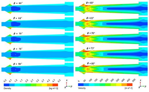
Figure 7 is the contours of air density ρ and air velocity v in xz plane at different ø (N=3, d=2.0mm). As shown in Figure 7, the air density ρ and air velocity v increased with the increment of ø, namely the vortex intensity was gradually improved.

(a) Density ρ(b) Velocity v
Figure 8 is the radial distributions of vz and vc at different ø (N=3, d=2.0mm). As shown in Figure 8, the vz and vc near the pipe wall increased with the increment of ø. However, the influence of ø on vz was small, and it could be ignored. This was because that the increment of ø led to the increase of circumferential velocity components. Consequently, vc rise up. When ø>75˚, the increasing range of vc was small. However, as shown in the velocity vector diagram which was not shown in this paper, much more turbulence and backflow occurred around the contraction part of Laval tube when ø is increased to a certain degree, such as ø=80˚. This impeded the increase of air speed inside yarn push pipe and vc, which resulted in the decrease of F.

(a) Near throat (b) Middle of Laval tube
The reasonable increase of ø will leads to increment of vortex intensity and vc, as well as the decrement of helix pitch. Thus, the length of yarn inside propulsion tube increased while F decreased. The occurrence of turbulence and backflow lead to the decrement of F. Therefore, there is no need to design a high value ø. Experiments proved (experiments methods and results see reference)12 that ø reached the peak value when ø=75˚ then went down with the increment of ø.
The influence of jet orifice structure on the flow field distribution inside the suction guns was analyzed in this paper. Results showed that the number of jet orifices controlled the flow diffusivity and directivity, which leads to the change of air density ρ and circumferential velocity components vc inside the yarn suction gun, and resulted in the change of yarn suction strength F. Appropriate diameter of jet orifice d was benefit for the formation of strong vortex, while avoiding normal shock wave. Thus, the best yarn suction efficiency could be achieved. The increase of ø enhanced the vortex intensity and vc, resulting in rise of F. Overlarge ø will produce turbulence and backflow, leading to decrease of F. The appropriate structure of jet orifice is: N=3, d=2.0mm, ø=75˚. F was closely related to the distribution of air speed, especially the vc. Normal shock wave was not benefit for improving the properties of suction gun, which should be avoid.
This research was financially supported by the Fujian Provincial Department of Science & Technology [2015H0030] and the Education Department of Fujian Province [No. JK2014042].
None.
Author declares there is no conflict of interest in publishing the article.

©2017 Li, et al. This is an open access article distributed under the terms of the, which permits unrestricted use, distribution, and build upon your work non-commercially.