Journal of
eISSN: 2574-8114


Research Article Volume 2 Issue 5
Fujian Provincial Key Laboratory of Functional Fiber Materials, Minjiang University, China
Correspondence: Yonggui Li, PhD, Fujian Provincial Key Laboratory of Functional Fiber Materials, Minjiang University, Fuzhou, Fujian, 350108, China, Tel 8659183761611, Fax 8659183761611
Received: July 13, 2017 | Published: August 18, 2017
Citation: Li Y, Ke H, Zhang M. Laval tube design of yarn suction gun for fully drawn yarn. J Textile Eng Fashion Technol. 2017;2(5):481-484. DOI: 10.15406/jteft.2017.02.00073
In order to demonstrate the effect of Laval tube structure of yarn suction gun on the yarn suction performance, throat diameter and throat length of the Laval tube were determined by theoretical analysis of the fluid field in the gun. 12 Laval tubes were designed, and yarn suction force (F) and mass flow rate of compressed air (G) were determined. Thereafter, yarn suction efficiency (η) was analyzed, where η=F/G. The rational geometrical parameters were obtained: converging angle of Laval tube α=90˚ and diverging angle of Laval tube β=6˚. The results indicated that there was a benefit to the airflow acceleration in the converging part of Laval tube and the formation of strong swirling flow by choosing the proper α, finally resulting in the improvement of η. The increase of super-sonic swirling airflow in the diverging section of Laval tube and the decrease of running resistance between the airflow and the yarn could be found when the reasonable β was selected, which also improved η. However, normal shock wave appeared in advance, the kinetic energy lost and the acceleration of airflow stopped due to the over-large β, leading to the decrease of η.
Keywords: yarn suction gun, laval tube, spinning machinery, yarn suction efficiency
The yarn suction gun (YSG), which is an indispensable part of the spinning machine for the production of fibers, is used to pick up a running yarn at the beginning of spinning or yarn breakage and take it to a bobbin, and also to transfer a yarn from a full bobbin to an empty one during the bobbin exchange step. The YSG is also used for producing nonwoven fabrics.1
In general, the compressed air is selected as the working fluid of the YSG. Some researchers proposed the YSG based on the idea of utilizing pressurized water instead of compressed air.2,3 A fine YSG should exhibit excellent properties such as providing powerful suction of a yarn with high energy efficiency and low consumption of the compressed fluid.
Miller reported the first patent of the YSG.4 Moreover, the improvement of Miller’s type YSG was also reported by Ashby5,6 and Bunting.7 This YSG had airflow geometry similar to that of an air-jet loom by virtue of Bernoulli’s principle, thus it could be used to handle the polyester yarn moving at a speed of 2700 m/min.8 Richter9 Vanderip10 used an air vortex to increase the capacity of the YSG, which was used to handling a yarn at a speed of 4500 m/min. The Miller’s and Richter’s type YSG were also synthesized to make a new one with less noise by McFall.11 Tseng12 carried out an improvement by adding an accelerator in the YSG, which was similar to the present YSG.
The super-high-speed spinning refers to the wind-up speed of 6000 to 10000 m/min or more. Usually, this spinning method is used for the production of fully drawn yarn (FDY) because partially oriented yarn (POY) and drawn textured yarn (DTY) are processed at relative low speed. However, the speed of the yarn sucked by the conventional YSG is less than 6000 m/min. For introduction of the super-high-speed winder, the rotation speed of the winding roller has to be slowed down so that the running yarn could be captured by YSG. Then the winding roller is sped up to the regular speed after threading. This result in the fact that the performance of the super-high-speed winder cannot be fully displayed and the available high speed is wasted in this case. Therefore, it is necessary to develop a new YSG with the super-strong suction capacity.
In order to provide the technological support for structural design of the YSG with high performances such as strong suction of yarn and low consumption of compressed air, the systematical studies on the effects of four geometrical parameters of YSG for polyester FDY on the yarn suction performance, flow field and yarn motion have been reported by researchers.13-18 The nozzle of the YSG was also improved by Li and coworkers.18 The jet orifice structure in the nozzle has a great effect on the fluid field in the YSG, and therefore affects the yarn suction efficiency.19 The yarn suction efficiency of the YSG also depends on the production conditions and yarn regularity.20
However, according to the literatures, there was no report about the effects of the Laval tube structure such as the diverging angle on the yarn suction performances of the YSG. Therefore, in this paper, the effects of the Laval tube structure on the yarn suction performances of the YSG for polyester FDY were investigated for improvement of the YSG with high suction performance.
Experimental apparatus and method
The schematic diagram of the experimental apparatus is shown in Figure 1. The compressed air flowed from the compressor to the rectification tank, and then went through the valve and flow meter. The air came from the rectification tank was regulated to the set pressure by the pressure adjuster. After that, it was supplied to the YSG. Yarns were sucked into the YSG from the yarn inhalation tube because of the vacuum region produced in the YSC. Finally, the air flowed out into the atmosphere with the yarns. These sucked yarns were collected to a waste box as the waste yarn and used for other end uses or producing regenerated yarn. The tension and speed of the yarns released from the bobbin were adjusted by the tension adjuster and feed roller, respectively. The yarn tension was measured by the YG2301A type tension meter produced by Changzhou Kejian Textile Instrument Co. Ltd. The yarn suction force (yarn tension) was used to illustrate the performance of the yarn suction. The mass flow rate of compressed air (G) was measured by an air flow meter. The yarn speed was tested by the Y007B type yarn speed tester produced by SDL Atlas Ltd.
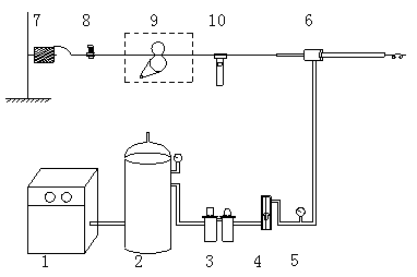
Figure 1 Schematic diagrams of the experiment apparatus: (1) compressor, (2) rectification tank, (3) valve, (4) flow meter, (5) pressure adjuster, (6) yarn suction gun, (7) bobbin, (8) tension adjuster, (9) feed roller and (10) tension meter.
Geometry of yarn suction gun
Figure 2 illustrates the structure of the YSG. It consisted of a yarn inhalation tube, nozzle including three jet orifices and yarn propulsion tube consisting of a Laval tube and a straight tube. The basic working mechanism has been described in the previous research paper.13 The two geometrical parameters of the Laval tube such as converging angle of Laval tube (α) and diverging angle of Laval tube (β) were investigated in this paper. Table 1 lists the values of these two geometrical parameters. In order to compare the results with the data reported in the previous research paper,13 the polyester yarn (166.7 dtex/48 f) was chosen, which a representative yarn was. And the feed speed of the yarn and supplied air pressure were set at 600 m/min and 0.5 MPa (gauge pressure), respectively.
Evaluation of yarn suction performance
The yarn suction force, speed of the sucked yarn and pressure at the inlet of yarn inhalation tube are the key indicators to evaluate the yarn suction capacity of the YSG. In order to determine the suitable geometry of the YSG from the viewpoint of energy efficiency, the performance of the YSG was investigated by yarn suction efficiency (η=F/G), defined as the ratio between the yarn suction force (F) to the mass flow rate of compressed air (G). This evaluation method has been used in the literatures.13-18
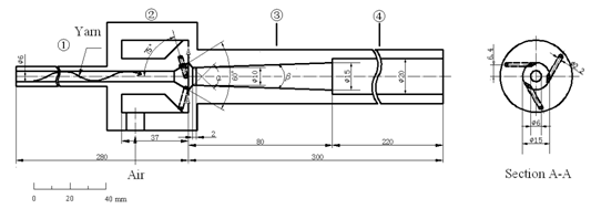
Figure 2 Illustration of the yarn suction gun (the number of jet orifices N=3) : (1) yarn inhalation tube, (2) nozzle, (3) Laval tube, (4) straight tube.
Geometry Parameter |
Value |
Converging angle of Laval tube α(˚) |
60, 75, 90, 105, 120, 135, 150 |
Diverging angle of Laval tube β(˚) |
2, 4, 6, 8, 10 |
Table 1 Geometry parameters of the Laval tube.
Design of the throat dimension
The airflow was accelerated by the Laval tube in the YSG. It is possible to attain the supersonic velocities in the diverging section when the sonic flow exists in the throat of the YSG. In this case, the air will continue to expand in the diverging section, the pressure decreases and the velocity increases.21
It is assumed that the airflow in the Laval tube is adiabatic and the fluid friction is negligible, thus the process is isentropic. Velocity of the airflow in the throat must be not less than sonic velocity when the supersonic flow is required in the diverging section. The condition of sonic flow at the throat is assumed (Mach number=1). The ratio of the cross-sectional area of the outlet to that of the throat is obtained as follows:22
Where A is the cross-sectional area of the outlet (m2), A* is the cross-sectional area of the throat (m2), d is the outlet diameter (m), d* is the throat diameter (m), M is the Mach number at outlet, k is the specific heat ratio (for air k =1.4). In this paper, d is equal to 15×10-3m. For the supersonic flow through the outlet of Laval tube, the M=2~2.5 was substituted into the above equation, from which d*= (9.24~11.50)×10-3m. This is the rational range of throat diameter.
The dimension of the throat is important for airflow field distribution in this transitional region, which is easily distorted due to the irrational throat dimension. The throat diameter was fixed at 10mm, which have been proved to be optimal value in the previous study.13
Theoretically, the smooth transition is required on the surface of the throat to make the airflow smooth transferring from the converging section to the diverging section. In other word, the throat length should be zero in theory, but it is very difficult to make the Laval tube with the throat length of 0 mm due to the high requirement of machining accuracy. Therefore, the throat length was set at 2 mm in this paper.
Converging angle of laval tube
The inlet diameter of the Laval tube is equal to the outlet diameter of the jet nozzle (i.e., 15 mm) for the connection between them. Variation of the converging angle of Laval tube (α) was obtained by changing the position of the throat and the length of the diverging section of Laval tube. The diverging angle of Laval tube (β) was fixed at 4˚. This value has been used in the previous studies.13,18
Figure 3 shows the effects of α on the yarn suction performances of the YSG. The yarn suction force (F) increased and then decreased with the increase of α, and it reached up to the maximum value when α was 90˚, as shown in Figure 3A. The converging section of Laval tube was designed to accelerate the airflow based on the law of conservation of mass. The value of the ideal α should match the value of the jet orifice angle, which would allow the injected compressed air to flow smoothly along the inner wall of the converging section of Laval tube and then go through the throat. It is very difficult to steer the injected airflow through the converging section when the value of α was too small, leading to the fact that the strong swirling flow cannot be formed and the F decreased. Otherwise, the backflow was formed due to the too large value of α, resulting in the decline of F.
Figure 3A reveals that there was no significant effect of the change of α value on the flow rate of compressed air (G). The yarn suction efficiency (η) showed the same change trend with the F with the variation of α. The η also reached up to the maximum value at α=90˚, as shown in Figure 3B. We concluded that the rational value of α was about 90˚ based on the values of η and F.
Diverging angle of laval tube
The Effects of the diverging angle of Laval tube (β) on the yarn suction performances were investigated by changing β and fixing α at 90˚. It is worthwhile to note that the length of the diverging section of the Laval tube was changed with the change of β. Therefore, the length of the straight tube was adjusted, while the length of the yarn propulsion tube was set at 300 mm.
The changes of the yarn suction force (F), the mass flow rate of the compressed air (G) and the yarn suction efficiency (η) as a function of β are shown in Figure 4. Figure 4A reveals that the F value increased with the increase of β value when β≤6˚. The value of F was reached up to the maximum when the β was 6˚, but it decreased with the further increase of β value. In the Laval tube, the airflow was accelerated to the velocity of sound in the converging section and then further accelerated to the supersonic velocities in the diverging section.21
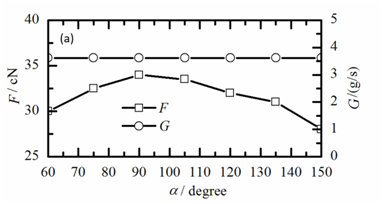
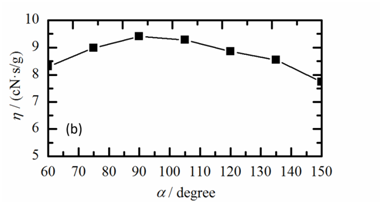
Figure 3 Effects of the converging angle (α) of the Laval tube on the performance of the yarn suction at β=4˚: (a) yarn suction force (F) and mass flow rate of compressed air (G), (b) yarn suction efficiency (η).
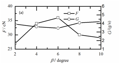
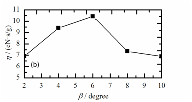
Figure 4 Effects of the diverging angle (β) of the Laval tube on the performance of the yarn suction at α=90˚: (a) yarn suction force (F) and mass flow rate of compressed air (G), (b) yarn suction efficiency (η).
The sucked air was transferred to the high-speed airflow in the helix in the yarn propulsion tube. The density of the air near the wall was higher than that of air near the centerline in the yarn propulsion tube. In other word, the airflow was biased toward the vicinity of the wall. The length of the diverging section of the Laval tube became over-large when the β was too small, which could led to the enlargements of the both of the length and the thickness of the supersonic flow area along the Laval tube wall. Therefore, the loss of kinetic energy increased with the increasing of the moving air resistance. Additionally, the friction force between the yarn and the tube wall also increased, resulting in the decrease of F.
The normal shock wave with the larger intensity moved upstream in the diverging section of Laval tube when the value of the β was too large, which caused that the acceleration of air stopped early and the air flow extremely expanded. There was no contribution to the increase of F because of the conversion of the kinetic energy to thermal energy. The flow through a shock wave is not isentropic, since part of the kinetic energy is converted into heat.21 The flow rate of the compressed air exhibited the opposite distribution compared with that of the F. Moreover, the change value of the G was too small, which can be neglected. Figure 4B indicates that the change curve of the η was similar to that of the F due to the negligible change of G. A large yarn suction force could be obtained by using the Laval tube with the appropriate diverging angle of β=6˚. Therefore, the results of the experiments suggested that the optimum value of β was 6˚ based on the consideration of the η and F values.
Comparison with the results of the previous studies
According to the previous researches,13,18 there was no report about the influence of the diverging angle of Laval tube on the values of the η and F when α and β were set at the 90˚ and 4˚, respectively. The results indicated that the optimum geometrical parameters of α and β were 90˚ and 6˚, respectively, and the η was improved about 10.6 %.
In order to improve the performances of the YSG, the twelve Laval tubes were made and the relationships between the Laval tube geometry and the performance of the YSG were discussed. The results suggested that the Laval tube processed the optimal performances when the geometrical parameters of the converging angle of Laval tube (α) and the diverging angle of Laval tube (β) were set at 90˚ and 6˚, respectively. Additionally, choosing the proper value of α was benefit to the acceleration of the airflow and the formation of the strong swirling airflow, leading to the improvement of the yarn suction efficiency. The super-sonic swirling airflow in the diverging section of Laval tube was easily accelerated and the running resistance between the air and the yarns significantly decreased by setting the reasonable value of β, thus the η was enhanced. However, when the value of the β was set at the large one, the normal shock wave happened in advance because the acceleration of the air was stopped and the kinetic energy was dramatically lost, which results in the low η.
This research was financially supported by the Fujian Provincial Department of Science & Technology [2015H0030] and Minjiang University [MJY14004].
None.
Author declares there is no conflict of interest in publishing the article.

©2017 Li, et al. This is an open access article distributed under the terms of the, which permits unrestricted use, distribution, and build upon your work non-commercially.