Journal of
eISSN: 2574-8114


Research Article Volume 3 Issue 4
1Defence Bio-Engineering & Electro Medical Laboratory, India
2EIS, Tata Consultancy Services, India
3Department of Nanoscience and Technology, Kuvempu University, India
4Lecturer, Acharya Institutes of Graduation Studies, India
5Assistant Professor, Ramaiah University of Applied Sciences, India
6Lecturer, Govt. Institute of Textile Technology, India
7Central institute of plastics engineering and technology, India
Correspondence: Indu Shekar R, Defence Bio-Engineering & Electro Medical Laboratory, CV Raman Nagar, Bengalure-560 093, India
Received: December 03, 2017 | Published: December 14, 2017
Citation: Indu SR, Raghu TS, Sanal F, et al. Investigation on the influence of fiber orientation on sliding wear and frictional characteristics of glass-carbon and twaron-carbon hybrid composites. J Textile Eng Fashion Technol. 2017;3(4):696-703. DOI: 10.15406/jteft.2017.03.00109
An experimental investigation was carried out to study the influence of fiber orientation on the wear and frictional characteristics of hybrid-epoxy composites. Unidirectional and bidirectional glass-carbon epoxy(GC) and Twaron-carbon epoxy (TC) composites were prepared using conventional wet hand-layup technique followed by vacuum bagging using an amine and an anhydride based curing agents. Wear and frictional tests were carried out with configuration of a pin on a rotating disc at normal loads of 30, 50 and 80N under dry sliding speed of 3 and 8m/s. It was found that hybrid composites containing bidirectional yarn systems have better wear resistance, lower wear loss and higher frictional coefficient compared to the unidirectional hybrid composites independent of the load, speed, nature of the fibers and hardener. TC composites were also found to exhibit better mechanical properties compared to GC composites. Scanning electron microscope (SEM) examination revealed that the fiber orientation has considerable effect on the wear, friction properties of hybrid composites and failure mode initiation.
Keywords: electron microscopy, friction, hardness, hybrid composites, sliding wear, two-body abrasion
UD, unidirectional; BD, bidirectional; MD, multidirectional; PPS, polyphenylene sulfide; SEM, scanning electron microscope; GC, glass-carbon; TC, twaron-carbon
Thermo-set based composites using epoxy resin systems currently dominate the composite industry. Glass-reinforced epoxy composites are extensively used in the structural composites of aircraft industry due to low shrinkage, ease of fabrication, chemical resistance, and higher mechanical and electrical properties. The above characteristics coupled with techno-economic considerations are mainly responsible for their extensive use in aerospace, automobile and marine engineering applications. The fiber reinforced epoxy composites offer high strength, stiffness, corrosion resistance, long fatigue life besides their ability to form complex shapes has also widen the scope of structural applications.1-3 However, the advent of high performance fibres (Carbon, aramids) has enhanced the scope of advanced structural composites as the above composites outperform the conventional glass-epoxy composites due to their superior mechanical properties. In recent years, more research work is being directed towards exploring the potential advantages of high performance fibres using hybrid concept. High temperature and high performance fibres based on Carbon, aramid fibers and their hybrids are extensively used in various configurations to meet wear and friction properties for specific applications.4 Lhymnhas reported that the orientation of the carbon fibers can significantly alter the abrasive wear performance of polyphenylene composites independent of the applied load and speed.5 Theoretically, it was predicted that the composites containing carbon fibers in the parallel direction and aramid fibers in the normal direction would be an ideal option for high wear performance.6,7 Bidirectional orientation of fibers, among the different orientations like unidirectional (UD), bidirectional (BD) and multidirectional (MD), provides unique solutions and enhances the functional performance to meet critical requirements of ever increasing demands on advanced materials. The concept of hybrid composites using high performance fibres has enhanced the scope of structural composites and can be suitably engineered to meet the desired performance besides offering reduction in weight and cost thereby enhancing the scope and capability of a designer to meet specific functional requirements in biaxial directions. The use of hybrid fibre systems will also address some of the important aspects related to drapability, strain to failure ratio while fabricating critical and irregular shaped components and provide conformability to highly complex contours. The typical characteristics exhibited by the hybrid composites are essentially a function of nature of fiber, structure induced parameters and the stacking sequence in addition to the process parameters followed during manufacturing. Most of the investigations carried out on biaxial fabrics for damage assessment have revealed that cracks initiate in the weft bundles. Hybrid fabrics encompassing different fibre systems is expected to offer better resistance to damage than the composites made out of single fiber in both warp and weft direction.
Wear is one of the most commonly encountered engineering problems in the industry leading to replacement of assemblies and components very often. There are five different types of wear; abrasive, adhesive, fretting, erosion and fatigue. Abrasive and adhesive wear often leads to replacements due to changes in the dimensions of mating parts. There are four different mechanisms in abrasive wear, viz., micro ploughing, micro cutting, micro fatigue and micro cracking. Hence, there is increasing interest to obtain optimal wear rate in polymer composites without compromising on the inherent properties of the matrix resin. Wear characteristics can be controlled substantially by optimum selection of volume or weight fraction of fibre, microstructure, morphology of the reinforcing phase, and the interface between fiber and matrix. With the increasing importance demanded by end users to enhance the lifetime of tribological components, data generated by wear studies have been found to play a major role. In fact, in many industrial and aerospace applications, many components for example, conveyor belt, shuttle, tillage tools and wind blades are subjected to two-body abrasive wear. Two-body abrasive wear is caused by the displacement of material from a solid surface due to hard particles sliding along the surface or when rigidly held over the solid surface.
The wear characteristics of carbon/epoxy composites were investigated by Lee et al.8 at different working conditions. Suresha et al.9 investigated the friction and wear loss of the carbon-epoxy and glass-epoxy composite by using pin-on-disc. Quintelieret al.10 investigated the friction and wear behavior of carbon fiber reinforced polyphenylene sulfide (PPS), and found that the wear behavior is essentially a function of orientation of fibre. It was observed that 0 and 90˚ disc position and the 0˚ disc position orientation have an earlier wear through the top layer of PPS than 45˚ disc positions, and perpendicular to the weft direction has an earlier wear through than the parallel 90˚ disc position.
Vishwanath et al.11 studied the tribo performance of three types of BD reinforcements (E glass, high strength carbon and Kevlar 49). For a given matrix, it was found that Kevlar composites exhibited better performance than glass fibre reinforced composites. Friedrich4 studied adhesive wear performance of three different types of reinforcements (glass, carbon and aramid fabrics) in epoxy resins and reported that Carbon and aramid based composites exhibit better performance in parallel and normal orientation respectively. It has also been reported12 that the co-efficient of friction and the wear rate of reinforced polymer depends on the fiber orientation; with superior wear resistance observed when the axis of the fibers is normal to the plane of sliding. This is attributed to the fact that orientation of fibers in the above direction are in the best position to support the load and effectively resist detachment from the matrix. In continuation to our ongoing efforts to develop a fiber reinforced epoxy composites with improved wear and friction performance13-17 an effort has been made in the present work to investigate the effect of fiber orientation on wear and frictional characteristics of hybrid composites (glass-carbon and twaron-carbon reinforced epoxy composites) under different conditions of applied load and speed. The effect of high and low temperature hardener system is also briefly investigated.
Materials used
E-Glass, Carbon (TC33) and Twaron (2200) were obtained from Toray and Teijin respectively. Glass-carbon (GC) and Twaron-carbon (TC) hybrid fabrics were woven on rigid Rapier loom at M/s Arun Fabrics, Bangalore. Glass yarn was used as warp & carbon yarn as weft in GC variety and Twaron yarn as warp and carbon yarn as weft in TC variety. Huntsman LY 556, with a viscosity of 10000-12000 cP at 25˚C and specific gravity 1.15-1.20 at 25˚C was used as resin system along with anhydride based hardener (HY 917) and amine based hardener (HY 951). Constructional particulars of hybrid fabrics used for fabricating composites are given in Table 1. The plies were dried in hot air oven for about 1hr to remove the moisture present in it. The prepared composites were characterized for their tribological and mechanical characteristics.
Properties |
Sample GC |
Sample TC |
Weave |
Plain |
Plain |
Warp |
E-Glass |
Twaron |
Weft |
Carbon |
Carbon |
Warp count, Tex |
300 |
127 x 2 |
Weft count, Tex |
TC-33 6K (400) |
TC-33 6K (400) |
Warp threads per dm |
60 |
60 |
Weft threads per dm |
47 |
31 |
Weight of warp |
180 |
152.4 |
Weight of weft |
192 |
128 |
Mass per unit area, g/m2 |
372 |
280 |
Table 1 Constructional particulars of hybrid co-woven fabrics used for fabricating composites
Procedures
Fabrication of composites laminates and samples: Conventional wet hand layup technique with vacuum bagging technique was used for the fabrication of the fiber reinforced composites. The smooth surface of mold plates was impregnated with a releasing agent to aid the release of laminates. Epoxy resin and hardener mixture in the ratio of 100:10 by weight was used as a matrix. A unidirectional (0˚ and 90°) and bidirectional (0˚ &90˚ and 90˚ & 0˚) hybrid fabrics cut as per the required dimension were used. The fiber loading in the composite was kept at 60 + 2 %. The individual fabric layers were impregnated with resin and stacked one over the other to obtain the desired thickness. A spacer layer and mould releasing layer was used in the process. The laminates were pre-cured and post cured at 80˚C and 120˚C for 4hrs and 2hrs respectively. Test specimens of required dimensions were cut using a water jet cutting machine.
Abrasive wear and mechanical studies: Two-body abrasive wear test was conducted by using a pin-on-disc machine as per ASTM D 3039. The surface of the sample (6 mm × 6 mm × 4 mm) glued to a pin of dimensions 6 mm diameter and 25 mm length, was kept in contact with metal disc. The surface of the samples is cleaned with a soft paper soaked in acetone before the test. The specimen weight is recorded using an electronic balance (A&D GR-300, 0.1 mg accuracy). The abrasion wear test was conducted on a track of 100 mm diameter. The composite specimens were abraded against a metal disc at a load of 30, 50 and 80N at an abrading distance of 1800m for 10 minutes at speeds of 3 and 8m/s. The difference between the initial and final weight of the specimen was measured as the wear loss. A minimum of three tests were conducted for each specimen was recorded to ensure repeatability of test data. Wear volume (ΔV) and specific wear rate (Ks) were calculated from the following equations18
(1)
(2)
Where, Δ mis the mass loss in gms, ρ is the density of the test material in g/cm3, ΔVis the volume loss in m3, L is the load in Newton and d is the sliding distance in meters.
The density of the composites was determined by using a high precision electronic balance using the Archimedes principle.
Hardness (Shore-D) of the samples was measured as per ASTM D2240, by using a Hiroshima make hardness tester (Durometer). Five readings at different locations were noted and an average value is reported.
Tensile properties were carried out on a fully automated Lloyd LR-20 kN Universal testing machine connected to a computer with DAPMAT software in accordance with the ASTM D-3039 procedure at a crosshead speed of 5 mm/min and a gauge length of 50 mm. Six samples were tested in each set and an average value is reported. All the tests were conducted at room temperature and 65 ± 5% RH.
The surface morphology of the specimens was examined by scanning electron microscope (SEM) JEOL JSM-6480LV. The samples were impregnated with a thin layer of gold by sputtering unit before being examined for morphology.
Wear loss
The wear test was carried out with the objective to analyze the influence of fiber orientation, nature of the fiber, applied load and sliding speed on wear loss of Glass-Carbon (GC) and Twaron-carbon (TC) epoxy composites (Figure 1).
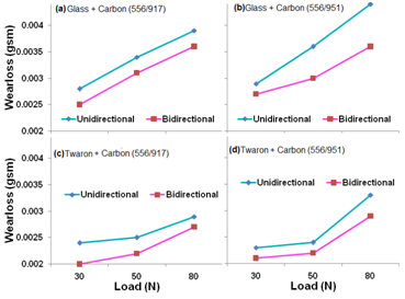
Figure 1 Wear loss of GC and TC hybrid composites as a function of load at a constant abrading distance, abraded against metal surface at sliding velocity of 3 m/s for different hardener systems in the matrix.
The wear loss results as a function of applied load at a constant abrading distance abraded at a sliding velocity of 3 m/s is shown in Figure 1. Figure 1 reveals that the hybrid composites containing bidirectional fibers have better abrasion wear resistance and lower wear loss as compared to the unidirectional hybrid composites. Further it is obvious from the figure that the wear loss of the composites increases with increase in applied load irrespective of the nature of fiber, fiber orientation and hardener due to micro cracks in the resin followed by wearing out of a certain amount of epoxy matrix and micro-fracture of fibers. GC composites show higher wear loss compared to TC composites. Between the anhydride (HY 917) and amine (HY 951) based epoxy resin curing agents (hardeners), anhydride cured resin shows better abrasion resistance and lower wear loss than the amine cured epoxy resins. The possible reason for the above behavior is due to the rigidity imposed by high temperature anhydride hardener (HY 917). It is also observed that the rate of wear loss is gradual in the case of TC composites and is attributed to the high inherent abrasion characteristics of aramid fibres compared to that of glass and carbon fibres.
Figure 2 shows the wear loss of GC and TC hybrid composites as a function of load at a constant abrading distance abraded against a metal surface at a higher sliding velocity of 8 m/s. Similar trend was obtained as observed at 3 m/s, but with the higher wear loss compared to those observed at 3 m/s speed.

Figure 2 Wear loss of GC and TC hybrid composites as a function of load at a constant abrading distance abraded against metal surface at sliding velocity of 8 m/s.
This result clearly shows that the wear loss increases with increase in load and speed irrespective of the fiber orientation and the nature of the fibers. The wear loss essentially depends on the initial resistance offered by matrix followed by micro cracking of the matrix. Subsequently, the load is transmitted on to the reinforcement fiber either on to the single fiber or bundle of fibers. In the case of yarn wherein the fibers are held together by frictional forces, the extent to which the material undergoes wear depends on the cohesive energy of the fiber bundle and the resistance offered to disassociate them. The cohesive energy between the fibers in the case of para-aramid fibers like Twaron is expected to be high compared to carbon fibers due to hydrophilic nature of the fibers. Further the torsional forces acting between the fibers effectively contribute to higher wear resistance as is observed in the case of TC composites. The effect of weave coupled with an amplitude of projection of longitudinal (warp) and transverse (weft) fiber system determines the extent to which the material offers resistance. Glass-carbon based hybrid composites, wherein both the fibers are susceptible to abrasive wear show higher wear loss compared to TC based composites. In case of TC hybrid composites, Twaron fibers are expected to control the wear loss due to its known higher abrasion resistance and the higher level of crimp amplitude of Twaron resulting as a result of the load imposed by glass due to its higher density. Glass-roving generally exerts a higher load on weft with a corresponding increase in weft crimp. The Twaron roving used as weft in the present case exhibits higher crimp amplitude and hence has contributed to the lower wear loss.
Specific wear rate
The variation of specific wear rate with applied load (30, 50 and 80 N) at different sliding speeds (3 and 8 m/s) under dry sliding conditions is depicted in (Figure 3) (Figure 4). Figure 3 reveals a drastic reduction in specific wear rate with an increase in applied load irrespective of the nature of the fiber, fiber orientation, hardener and sliding speed. This is because after initial abrasion of epoxy matrix, the exposed fibers and some of the worn particles clog the abrasive paper and slow down further wear loss. The specific wear rate of unidirectional epoxy composites is higher compared to the bidirectional composites. TC composites have shown higher specific wear rate compared to GC composites.
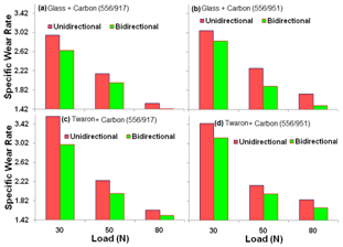
Figure 3 Specific wear rate of GC and TC hybrid composites as a function of load at a constant abrading distance abraded against metal surface at sliding velocity of 3 m/s.
Figure 3 reveals a drastic reduction in specific wear rate with an increase in applied load irrespective of the nature of the fiber, fiber orientation, hardener and sliding speed. This is because after initial abrasion of epoxy matrix, the exposed fibers and some of the worn particles clog the abrasive paper and slow down further wear loss. The specific wear rate of unidirectional epoxy composites is higher compared to the bidirectional composites. TC composites have shown higher specific wear rate compared to GC composites. Between the anhydride (HY 917) and amine (HY 951) based epoxy resin curing agents, anhydride cured resin system has shown higher specific wear rate compared to amine cured epoxy resins. The variation of specific wear rate with varying loads from 30 N to 80 N follows a linear behavior. This can be attributed to the following reasons:
At lower load with varying velocity, low modulus polymer matrix was exposed to abrasion and hence, the higher specific wear rate is observed. At higher loads, with varying velocity, high modulus fabric was exposed to abrasion, which showed lower specific wear rate. This is due to high modulus values of fibres (70 to 200 GPa) which exhibit better resistance against abrasion. This in turn necessitates that the abrasive particles have to work more to facilitate failure in the fibers (i.e., much higher amount of energy is required to facilitate fiber failure). Thus, the rate at which the material is removed with respect to the load decreases (Figures 2a-2d). This data indicates that the specific wear rate is a combined effect of applied load, abrading distance and velocity (Figure 4).
Figure 4 shows specific wear rate of GC and TC hybrid composites as a function of load at a constant abrading distance abraded at sliding velocity of 8 m/s. In this speed also, similar trends were obtained as observed at a sliding velocity of 3 m/s, but with higher specific wear rate than that observed at 3 m/s speed. This clearly shows that specific wear rate increases with an increase in load and speed irrespective of the fiber orientation and the nature of the fibers. During sliding wear, the long fibers orientated against the abrading wheel offer less resistance to micro-cracks as compared to the fibers in the parallel orientation. Due to sliding stress, the fiber-matrix bonding is weakened and releases the fibers as small strands (debris). With an increase in load, the micro cracking of resins followed by micro cutting process of fibres into small strands also increase proportionately, but the presence of debris on abrading surface hinders further abrasion. Hence a decrease in wear rate is observed with an increase in the load.
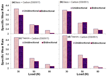
Figure 4 Specific wear rate of GC and TC hybrid composites as a function of load at a constant abrading distance abraded against metal surface at sliding velocity of 8 m/s.
Co-efficient of friction
The variation of co-efficient of friction of GC and TC hybrid composites with applied loads (30, 50 and 80 N) at different sliding speeds (3 and 8 m/s) under dry sliding conditions is shown in Figures 5 & 6. From the observations of these graphs, it can be seen that coefficients of friction decrease with increase in applied load. The increasing applied load increases the temperature at the interface.
The 'co-efficient of friction' (µ), is the measurement of resistance to friction as related to the effect of how smooth or rough a surface is to prevent material to “slip” across the surface. It is a dimensionless scalar value and it is the ratio of the frictional force between two bodies and the force pressing them together and is a strong function of the nature of materials used. Figure 5 reveals that the coefficient of friction of bidirectional composites is higher compared to unidirectional composites irrespective of the applied load, nature of fiber and hardener and decreases with increase in applied load. TC composites show higher co-efficient friction than that of the GC composites. Between the anhydride (HY 917) and amine (HY 951) based epoxy resin curing agents, anhydride cured resin has shown higher coefficient of friction as compared to amine cured epoxy resins (Figure 6).
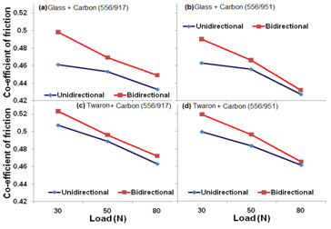
Figure 5 Coefficient of friction of GC and TC hybrid composites as a function of load at a constant abrading distance abraded against metal surface at sliding velocity of 3 m/s.
Figure 6 shows the coefficient of friction of GC and TC hybrid composites as a function of load at a constant abrading distance abraded against a metal surface at sliding velocity of 8 m/s. In this speed, also, similar trends are obtained as observed at 3 m/s, but with lower co-efficient of friction than that observed at 3 m/s speed. It is also observed that the co-efficient of friction decrease with increase in applied load and speed and is attributed to higher temperature gained at the interface under dry sliding conditions. The rise in temperature weakens the matrix-fiber interface due to transfer of thermal energy. As a consequence of above heat transfer, the fibers become loose in the matrix and shear easily due to axial thrust. GC composites exhibits a lower co-efficient of friction compared to TC composites. This improvement helps in the anti-frictional behavior of the hybrid composites. Our views in this regard are in accordance with the conclusions reported by other researchers.19-24

Figure 6 Coefficient of friction of GC and TC hybrid composites as a function of load at a constant abrading distance abraded against metal surface at sliding velocity of 8 m/s.
Worn Surface examination with SEM
The worn surface features of the composite specimens were examined using a scanning electron microscope (SEM). The SEM images of the worn surfaces of GC and TC composite samples subjected to applied loads of 30, 50 and 80 N at 8m/s velocity are shown in Figures 7-10. Matrix wear, fiber wear, fiber fracture and the fiber-matrix interfacial deboning are the four steps in the wear of polymer composites. The worn-out surface features of GC unidirectional composites (556/917) and (556/951) are shown in Figures 7ia-c and Figures 7iia-c respectively. The SEM images show more damage to the matrix and fibers subjected to higher loads Figures 7i(b) & 7i(c) and Figures 7iib & 7ii(c) than that compared samples subjected to lower loads Figures 7i(a) & 8ii(a). Figure 7i(b) & 7ii(b) also shows micro-cracking, chip formation, exposure of fibers, and less fiber breakage. As seen in Figure 7ic & Figure 7iic, fiber cutting and void formation due to chip coming out of matrix is seen predominantly perpendicular to the wear direction. There is evidence of matrix removal and deep furrows in the matrix as shown in the Figure 7ic & Figure 8iic. Furthermore, severe damage to the fibers, crushed and fragmented fibers, and delamination between fiber and matrix were also noticed at higher loads as shown in the Figures 7ib-c & Figures 7iib-c.

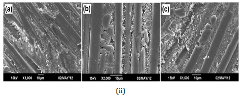
Figure 7 SEM photo micro graphs of worn surface of GC (556/917) – (i) and GC (556/951)- (ii) unidirectional composites abraded at loads (a) 30, (b) 50 and (c) 80N.
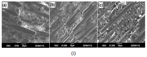
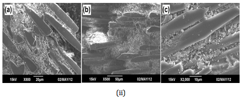
Figure 8 SEM photo micro graphs of worn surface of GC (556/917) – (i) and GC (556/951) – (ii) bidirectional composites abraded at loads (a) 30, (b) 50 and (c) 80N.

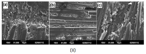
Figure 9 SEM images of worn surface of TC (556/917) – (i) and TC (556/951) – (ii) unidirectional composites abraded at loads (a) 30, (b) 50 and (c) 80N.
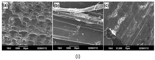
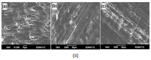
Figure 10 SEM photomicrographs of worn surface of TC (556/917) – (i) and (556/951) – (ii) bidirectional composites abraded at loads (a) 30, (b) 50 and (c) 80N.
The worn-out surface features of GC bidirectional composites (556/917) and (556/951) abraded at 30, 50 and 80N loads are shown in Figures 8ia-c & 8iia-c. The abrasive wear loss of GC bidirectional composites (556/917) and (556/951) is less as compared to GC unidirectional composites of (556/917) and (556/917), because of the directional orientation effect of fibres in one specific direction. This results in higher wear rate causing increased wear which further increases with increase in load and velocity. The GC bidirectional composites (556/917) and (556/951) showed less matrix failure, because both glass and carbon fibers are in stacked in two directions (Figure 8).
SEM images of the worn surface of GC bidirectional composites (556/917) and (556/951) for 30 and 50N showed less matrix damage as shown in Figure 8ia-b & Figure 8iia-b, whereas SEM images at higher loads Figure 8i(c) & Figure 8ii(c) reveals fiber-matrix failure followed by breakage of fibres and form voids due to small strands of individual fibres removed from the matrix. The SEM images clearly suggest the role of fibre orientation on the abrasive wear.
The worn-out surface features of TC unidirectional composites abraded at 30, 50 and 80N are shown in Figures 9ia-c (556/917) and Figures 9iia-c (556/951). SEM images of TC composites shows very less wear loss as compared to GC composites. The surface features of worn surfaces of TC bidirectional composite of (556/917) and (556/951) abraded at 30, 50 and 80N are shown in Figures 10ia-c & 10iia-c respectively.
SEM images of TC composite shows very less damage as compared to unidirectional composites. At 80N load, the wear damage is more compared to lower load condition and fibers cracks are seen which result in the formation of voids between the fibers. From the morphological behaviors and tribological results observed it can be concluded that the TC composites exhibits less wear and can be explored for applications where anti-wear properties are of prime importance.
Mechanical properties
The mechanical properties of uni and bidirectional oriented GC and TC composites are presented in Table 2. From the data generated, it can be observed that the bidirectional composites exhibit higher tensile strength, tensile modulus; tensile elongation and surface hardness compared to unidirectional composites and is attributed to the presence of two competent yarn systems in both the directions which impede the propagation of failure along the loading direction. The density of bidirectional composites were found to be slightly less owing to the density differential of different fibre systems used and the absorption characteristics of matrix. Although the presence of voids due to different nature of fibres used is expected to lower the mechanical properties, the same is not observed in the bidirectional composites possibly due to the fact that the inherent properties of fibres have dominated over the small variation observed in the density results. Table 2, further shows that GC composites exhibit higher tensile strength, higher tensile modulus and lower tensile elongation irrespective of the fiber orientation and hardener. It is interesting to note that mechanical properties of composites cured by amine hardener (HY951) have better tensile strength and hardness but less tensile modulus and tensile elongation compared to anhydride hardener (HY917) irrespective of the fiber orientation and nature of the fiber. In tensile strength tests, the fibers in a composite fail at different stress levels as the applied load increases. In bidirectional composites the presences of two competent yarn systems effectively support one another to withstand the load resulting in increased tensile strength than that of unidirectional reinforced composites.
Composition of Composites |
Density, (g/cm3) |
Surface Hardness (Shore D) |
Tensile Strength (MPa) |
Tensile Modulus (MPa) |
Elongation at Break (% ) |
GC(917) (0 &90˚) |
1.5132 |
86 |
204.6 |
2411 |
15.5 |
GC(917) (0˚&90˚ ) and (90˚& 0˚) |
1.4727 |
89 |
288.4 |
2510 |
17.7 |
GC(951) (0 &90˚) |
1.5472 |
92 |
252.7 |
2100 |
19.2 |
GC(951) (0 &90˚)and (90˚&0˚) |
1.5463 |
93 |
319.4 |
2410 |
20.9 |
TC(917) (0 &90˚) |
1.1698 |
92 |
194 |
2177 |
18.4 |
TC(917) (0 &90˚) and (90˚&0˚) |
1.1487 |
94 |
223.6 |
2212 |
19.4 |
TC(951) (0 &90˚) |
1.2049 |
93 |
247.4 |
2097 |
19.3 |
TC(951) (0 &90˚) and (90˚&0˚) |
1.123 |
95 |
269.9 |
2268 |
23.8 |
Table 2 Physi-mechanical properties of uni and bi directional oriented glass-carbon and twaron-carbon hybrid composites
An effort has been made to demonstrate the wear and frictional properties of unidirectional and bidirectional oriented GC and TC hybrid composites. The studies were aimed at exploring the possibility of using hybrid composites for aerospace structural composite applications in which the temperature can reach up to 150˚C and where low friction and low wear are critical requirements. From the abrasive wear and frictional studies the following conclusions are drawn:
None.
Author declares there is no conflict of interest in publishing the article.

©2017 Indu, et al. This is an open access article distributed under the terms of the, which permits unrestricted use, distribution, and build upon your work non-commercially.