Journal of
eISSN: 2574-8114


Short Communication Volume 1 Issue 5
1Technische Universitaet Dresden (TUD), Germany
2Roma Strickstoff-Fabrik Rolf Mayer GmbH & Co. KG, Hertenwinkelstr, Germany
3Maschinenfabrik HARRY LUCAS GmbH & Co. KG, Germany
Correspondence: Eric Haentzsche, Institute of Textile Machinery and High Performance Material Technology (ITM) at Technische Universitaet Dresden, Hohe Strasse 6, 01069 Dresden, Saxony, Germany, Tel 49-351-46331635
Received: March 03, 2017 | Published: April 25, 2017
Citation: Haentzsche E, Wendler J, Ruder T, et al. Integration of additive threads in stitch wale direction of circular knitted fabrics for smart textile applications-add-on device with rotating yarn feeder for double-jersey and interlock machines. J Textile Eng Fashion Techno. 2017;1(5):165-170. DOI: 10.15406/jteft.2017.01.00028
In the context of a research co-operation as part of the Central Innovation Program for SMEs (ZIM), an innovative and cost-effective add-on device for large circular knitting machines (LCKM) has been developed and realized, with which an additional thread sheet can be knitted into right-right (RR) and interlock circular -knitted fabrics in stitch wale direction. In combination with weft yarns simultaneously incorporated in stitch course direction, this allows the production of lattice-like, interconnected panel heating elements in the fabric structure in a single production step. These can be used for textile heating sheet and sensor elements. Using a panel-heating element made of elastic and electrically conductive yarns in an interlock circular-knitted fabric as an example, the potential of the method is shown for an integrative manufacture of functionalized circular-knitted fabrics for heatable textile products in the field of home textiles.
Keywords: double-jersey fabrics, accessory equipment, additive thread, thread integration, smart fabrics, textile panel heating element, home textiles, needle cylinder, heatable textile structures, hybrid twisted yarn, heating blankets, rib needle system, knitting cylinder circumference, skipped rib needle, parallel resistance
LCKM, large circular knitting machines; RR, right-right; MHL, maschinenfabrik harry lucas gmbh & co; LTLS, loop-thread laying system; LTL, loop-thread layer
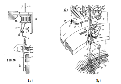
A number of special machines are available for the integration of additional threads in circular-knitted fabrics, for instance from Maschinenfabrik Harry Lucas GmbH & Co (MHL). Other approaches are documented in patents.1−7 These include primarily technical-constructive solutions for Single-Jersey machines Figure 1A with only a single needle bed, which allows an incorporation of additional thread material in stitch wale direction by overhead feeding to the vertically arranged cylinder needles, or extensive and sophisticated modifications of standard circular knitting machines with a standing needle cylinder and revolving creel Figure 1B.

Figure 1 Schematic of loop thread laying mechanism for Single-Jersey machines according to patent (a) and modified Double-Jersey machine with non-rotation knitting cylinder but rotating creel according to patent (b).
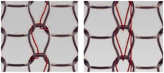
A novel method developed in co-operation with MHL, and roma Strickstofffabrik Rolf Mayer GmbH & Co. KG (ROMA), and a related add-on device conceptualized as an optional extension for existing Double-Jersey and interlock circular knitting machines allows the textile-technical integration of additional threads running in stitch wale or production direction. In particular, this concern electrically conductive thread constructions as conducting paths or routings for the functionalization of technical right-right-crossed or interlock knitted fabrics. The inclusion of such textile functional thread structures in right-right-crossed knitted fabrics on Double-Jersey and interlock circular knitting machines is not feasible at the current state of the art. With the so-called dynamic loop-thread laying system (LTLS), planar, heatable textile structures or sensor elements can be integrated in circular-knitted fabrics, which can be manufactured in a single run without interrupting the knitting process, owing to the loop-adapted integration of functionalized additional thread material in stitch wale direction offered by the LTLS, in combination with basic weft and loop threads inserted in stitch course direction Figure 2.

Figure 2 Schematic of tow embedding forms of an additive functional thread in stitch wale direction as loop (left) or pillar stitch (right) using the LTLS.
The presented approach of the knitting-in method of additional thread sheets in stitch wale direction is based on a loop-thread layer (LTL) that has been applied for patent.8 The add-on device described in the patent Figure 3 has been extended within this research effort: With each LTLS, up to five additional threads can be fed as plating into the rib needles, which are raised to pick-up or knitting position, and can be interlaced in stitch wale direction during the subsequent stitch formation.

Figure 3 Prototype of the loop thread laying system (LTL) device according to patent application [8] (l.) and assembly situation on a 14 in. Double-Jersey machine Mayer & Cie IV2.0 (r.).
A total of two LTLS prototypes are mounted on a passively driven carrier ring construction oriented concentrically around the knitting cylinder of a large circular knitting machine (LCKM) in order to evaluate their operability. By processing electrically conductive non-ferrous metal-textile hybrid twisted yarns made from elastane-copper filaments as the weft threads in stitch course direction, and by incorporating cabled and braided stranded copper wire in stitch course direction of a polyester (PES) circular-knitted fabric with the LTLS, elastic functional textiles with a resistive panel heating element have been produced. The stranded copper wire running in stitch wale direction serves as routing on both sides, allowing the electrical contacting of a panel heating element made of elastane-cupper hybrid twisted yarn, oriented in weft direction. This makes the previously necessary sewing application of woven stranded copper wires onto both sides of the circular-knitted fabric obsolete. ROMA currently offers circular-knitted fabrics with such functionalization as heatable mattress covers and heating blankets for horses.
Prototype of an add-on device for the incorporation of a single additive loop thread in circular knitted fabrics
A schematic for the LTL prototype with only a single additional thread being fed to a rib needle is shown in Figure 4. The purely mechanical add-on device is passively driven by the rotation of the knitting cylinder. The single sequences of the additional thread feeding to the rib needle system of a large Double-Jersey circular-knitting machine realizable with this device are shown in Figure 5.

Figure 4 Functional elements of LTL prototype of patent application [8]: cylinder needle (5), rib needle (6), support rail (13), raising cam (14), track rollers (25), contact wheel (15), guide needle (17), rotating finger (24), and mechanical linkage (10).
The LTL prototype, coupled with the knitting cylinder of the LCKM by a tension belt, is moved in a rotatory motion by the rotation of the knitting cylinder, using a support rail (13) and keeping the same rotational speed. The aligning orientation of the rotational axis of the rotating finger (24) is fixed to a longitudinal axis of a rib needle (6) and cannot be offset by needle gages for principle-inherent reasons. Raising cams (14) are mounted on the support rail according to the desired number of incorporation points of the additional thread material in stitch wale direction. These cams (14) are positioned in front of the cylinder needle (5) cam assemblies and adapted to the assembly curve with regard to their geometrical dimensions. This ensures that the feeding motion of the LTL can be synchronized with the raising motion of the rib needles. When crossing the raising cams, the vertical displacement of the contact wheel (15) drives the mechanical linkage (10), which causes a 220˚C rotational motion of the rotation finger (24) around the opened needle head of the rib needle raised into pick-up or knitting position, and inserts the loop threads into the needles Figure 5(2) . The rotational movement between the guide needle (17), mounted on the rotating finger, and the top edge of the fabric creates a balloon, which allows a secure feeding of the additional thread, as the guide needle is not dipped into the needle spaces between adjacent rib needles, thus reducing the risk of needle collisions. After the drawing-in movement of the rib needle, in which both loop and plated additional thread are stitch-formed together (Figure 5(3) & 5(4)), the rotating finger is reverted (24) by rolling the contact wheel (15) over the sloping edge of the raising cams (14).

Figure 5 Sequence of additive loop thread incorporation in stitch wale direction of a circular knitted fabric using the LTL prototype described in patent application [8].
Figure 6 show a circular-knitted fabric produced using the described method and the LTL prototype on a 14 in. Mayer & Cie IV2.0 machine. The illustration clearly displays the real, structural interlacing of the additional yarn in stitch wale direction, as opposed to filler and weft threads. Depending on the number of LTLs mounted on the knitting cylinder circumference, more of the additional thread sheets running in stitch wale direction shown in Figure 6 can be integrated. The distribution along the fabric circumference can be adjusted by the angular distance of the LTL. The incorporation density of the additional thread can be adjusted by the number of raising cams (14) mounted on the support rail (13). If no incorporation occurs at a particular cam assembly or a cam assembly sequence, the additional thread is floated over the number of stitch courses correlating with the number of skipped rib needle cam assemblies.

Figure 6 enmeshed 50 µm copper wires (material-no.2.0065, J.G. Dahmen GmbH & CO. KG) integrated in stitch wale direction of a circular knitted fabric produced on a 14 in. Double-Jersey machine with E20 machine gauge by usage of the LTL prototype.
Further development of an additive loop thread laying system (LTLS) and operating principle
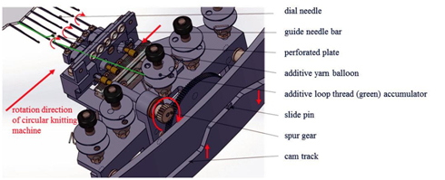
The innovative method for the incorporation of a sheet consisting of up to five additional threads in stitch wale direction of a Double-Jersey or interlock circular-knitted fabric based on further development of the functional principle described above is realized with the additive loop thread laying system (LTLS) shown in Figure 7. The system was constructed in the framework of BMWi research project ZIM KF2048939PK3, and manufactured in co-operation with MHL. It is conceptualized as a saleable add -on device for existing LCKMs regarding the feed able additional threads, and gives circular knitting factories an extension of their machine functionality at manageable additional costs and time expenditure. Two offset LTLSs are installed and tested on an interlock circular knitting machine of the knitted fabric manufacturer ROMA.

Figure 7 Schematic of the additive loop thread laying system (LTLS) for the integration of additive loop yarn sheets in stitch wale direction of designed as accessory equipment for large circular knitting machines.
Matching the desired floating length of the additional thread sheet in stitch wale direction over a certain number of stitch courses, cam track blocks are positioned on the circular knitting machine foundation in radial extension of the active rib needle cam assembly along the circumference of the planned circular knitted fabric. Each cam track block of the LTLS before a rib needle cam assembly feeds an additional thread into the rib needle and creates one intermeshing with the circular-knitted fabric per stitch course. If the number of additional thread ribbons along the circumference of the circular knitted fabric needs to be increased, additional LTLSs have to be mounted on the support rail. The length and slope steepness of the inlets and outlets of the cam track Figure 7 are adapted to the geometry of the rib needle rising curve.
The LTLS is mounted on a spur-cut drive ring. Figure 8 shows the coaxial assembly of the drive ring and its propulsion by means of an angular gear coupled to the main drive of the LCKM. This ensures the synchronous rotational movement of the knitting cylinder of the LCKM and the LTLS(s) moving along the cylinder circumference and mounted on the drive ring. In Figure 9, the assembly situation of both LTLSs on the circular knitting machine is shown.

Figure 8 CAD model of the drive ring acting as LTLS carrier (l.), top view during its installation onto the circular knitting machine with dismantled rib dial (m.) and mounted angular gear synchronized the LTLS drive ring with the knitting cylinders drive (r.).

Figure 9 Detailed view of non-rotating cam track carrier and LTLS mounted on drive ring and its bearing (l.); total view of two LTLS rotating with synchronized revolution in front of the knitting cylinder of interlock circular knitting machine (r.).
Due to the negative lifting of the slide pin at the downward slanted flank of the cam track and the rotation of the spur gear initiated by it, the guide needle bar of the LTLS completes a rotation around the longitudinal axis of the opened rib needle heads. The balloons created between the fabric top edge and the guide needles insert the additional thread sheet into five rib needles at the same time. After the stitch formation motion of the rib needles, the contact pin on the ascending slope of the assembly curve glides back into its initial position, and the guide needle bar rotates back.
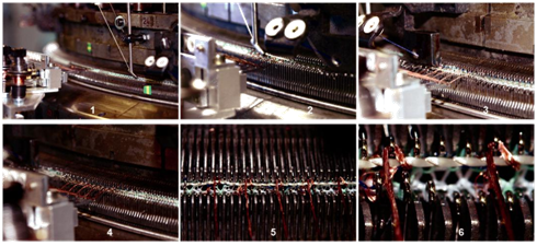
In first production tests, two additional thread ribbons consisting of five stranded copper wires are incorporated into a PES circular-knitted fabric by means of two separate LTLSs on the same LCKM. The additional thread ribbons connect an elastane-copper hybrid twisted yarn inserted in stitch course direction as the weft thread. Figure 10 shows the determined incorporation sequence over a total of six cam assemblies in rotation and production direction of the RR-LCKM.

Figure 10 Additive loop thread laying sequence using LTLS: rib needle clearance into pick-up position & additive loop thread laying (1), elastane-copper-hybrid twisted weft yarn insertion (2), pick-up position of rib needle and standard loop thread insertion (3), rib needle clearance into pick -up position & additive loop thread laying (4-5), standard loop thread insertion and stitch formation (6).
The weft thread is most securely contacted by the additional thread sheets if their insertion into the gripping rib needles is followed by the feeding of the weft thread under the rib needles and behind the cylinder needles at the subsequent cam assembly system, which is configured in the knitting position Figures 10(1)-(3). The additional threads located in the head of the rib needle are not formed into loops. Afterwards, the additional thread is inserted again with the LTLS (without stitch formation, i.e. half meshes and additional threads remain on the opened needle latch), using two additional modified dial cams in pick-up position. The incorporation of the additional thread sheet and the interlacing/contacting of the weft threads is completed by the loop formation (first simultaneous stitch formation of the additional threads with mesh thread) on the cam assembly system located after the modified dial cams. Figure 11 shows a section of a PES circular-knitted fabric structure with two additional thread ribbons consisting of five stranded copper wires each, which contacts the elastane-copper twisted yarns running in every sixth stitch course. The fabric structure was manufactured using the integration sequence described above. As two such routing ribbons are incorporated at the fabric circumference, a parallel resistance is created and can be utilized as a resistive heating element.
By using two novel LTLS add-on devices on a large circular knitting machine, and developed further on patent application DE102011003414A1,8 two additional copper thread sheets have been knitted into right-right circular-knitted polyester circular knitted fabric in stitch wale direction. In combination with elastane-copper hybrid weft yarns simultaneously incorporated in stitch course direction, the production of an interconnected panel-heating element in the fabric structure in a single production step has been successfully demonstrated.
The attainable contacting quality between the stranded copper wires in wale and stitch course directions, which is achieved by the binding pressure caused by the optimized incorporation sequence allows a consistent, even heating of the knitted fabric structure when an electrical power (I=6,78 A, U=10 VDC) is applied Figure 12. The achieved median heating field temperature is θ=140˚C, at a nominal heat output of 68 VA. The temperature of the stranded wires serving as electrical feed line, however, only reach median temperatures of θ=57˚C and thus fulfill the knitted fabric manufacturer's requirements. In a variation of the incorporation of stranded copper wires at identical dimensions of the heating panel, only about 50 % of the heating wires in stitch course direction can be contacted Figure 12, which decreases the nominal heating output to 30 VA. Notwithstanding the additional thread integration sequence described in Fig. 10, the threads are fed into rib needles raised into knitting position Figure 10(1)-(5).

Figure 12 IR thermal imaging of textile panel heating elements [LxB] = 315x135 mm2 with homogenous radiation of the heating copper-elastane hybrid wires aligned in course direction (horizontal) and their both-sited electrical interconnection in stitch wale direction (vertical) by the additive copper loop threads without any apparent thermal hotspots (l.) and with defective joints of the heating wires in course direction due to the suboptimal percentage crimp of the additive loop threads (r.).
The sub-projects KF2048939PK3, KF2136504PK3 (roma Strickstofffabrik Rolf Mayer GmbH & Co. KG) and KF2502904PK3 (Maschinenfabrik Harry Lucas GmbH & Co. KG) were funded through the AiF within the “Central Innovation Programme for SMEs (Zentrales Innovations program Mittelstand-ZIM)-Cooperation projects” from funds of the Federal Ministry for Economic Affairs and Energy (BMWi) by a resolution of the German Bundestag.
None.
Author declares there is no conflict of interest in publishing the article.

©2017 Haentzsche, et al. This is an open access article distributed under the terms of the, which permits unrestricted use, distribution, and build upon your work non-commercially.