Journal of
eISSN: 2574-8114


Review Article Volume 1 Issue 1
Institute of Textile and Clothing, Hong Kong Polytechnic University, Hong Kong
Correspondence: Hong Hu, Institute of Textile and Clothing, The Hong Kong Polytechnic University, Hung Hom, Hong Kong
Received: August 04, 2016 | Published: January 2, 2017
Citation: Hu H, Zulifqar A. Auxetic textile materials-a review. J Textile Eng Fashion Technol. 2017;1(1):1-15. DOI: 10.15406/jteft.2017.01.00002
Auxetic textiles are materials which possess negative Poisson’s ratio, this implies that in contrast to conventional textile materials if they are stretched in longitudinal direction, a marginal expansion will results in transversal direction. Auxetic textile materials have become a point of focus for many researchers in recent past years. This paper reviews the achievements in the area of auxetic textile materials including fibres, yarns, fabrics and textile reinforcements for composite applications. It is aimed that this review will be helpful for future advancement in the area of auxetic textile materials.
Keywords: auxetic, negative poisson’s ratio, textile structures, fibres, reinforcements
Auxetics are materials that have a negative Poisson's ratio. The term auxetic was derived from the Greek word (auxetikos) which means "that which tends to increase" by Evans K1 of the University of Exeter. In contrast to most conventional materials, auxetic materials possess the property that becomes fatter when stretched and narrower when compressed as shown in Figure 1. This occurs due to their hinge-like structures, which flex when stretched. It is claimed that auxetic materials have enhanced mechanical properties like shear modulus, energy absorbance, vibration damping, sound absorption and sync-elastic behavior.2−10
The Poisson’s ratio υ is calculated using the following equation 1.
(1)
Where is the axial strain and is the transverse strain.
The Poisson’s ratio is an elastic constant and is independent of the material scale. Therefore auxetic materials can be single molecules or a particular structure of macroscopic to micro level.11−17 The known naturally and manmade auxetic materials include metals, silicates, zeolites, laminates, gels, composites foams and polymers.18−35 These materials are incorporated as core materials to produce sandwich panels, to reduce creep buckling failure, drug release systems, vibration damping and energy absorbance textiles.36−40
Alderson K et al.19 produced a micro porous form of ultra-high molecular weight polyethylene (UHMWPE), capable of exhibiting large negative Poisson's ratios as low as -1.2 depending on the degree of anisotropy in the material. Liu P et al.32 developed liquid crystalline polymer (LCP). The arrangement of laterally attached rods in a main chain of LCP is shown in Figure 2a. The nematic field leads to orientation of the laterally attached rods parallel to the polymer chain axis. Under tensile stress as shown in Figure 2b, full extension of the polymer main chain forces the laterally attached rods normal to the chain axis leading to an expansion in the direction normal to the chain axis and hence to auxetic behavior. It is important to consider that the laterally attached rods should be sufficiently long, in order to increase the inter-chain distance and ultimately induce the auxetic behavior. Alderson A et al.36 produced polymeric monofilaments displaying auxetic behavior. The produced filaments had a microstructure of interconnected surface-melted powder particles. The structure and deformation mechanisms at the micro scale, rather than at the molecular level (as compared to conventional filaments extruded from a fully molten polymer) are responsible for enhanced mechanical properties, including the auxetic effect. In another study produced auxetic poly propylene fibres by using thermal processing technique.18 A large value of Poisson’s ratio (v = -0.6) was obtained when measured by using video extensometry. A novel method to produce auxetic polyester fibres have been reported by Ravirala N et al.41 The polyester granules were grinded by using an in-house cryogenic grinding and particles of less than 150µm were collected to carry out the extrusion. The extrusion was carried out at higher temperature (230 °C) profile and gradually decreased the temperature to 210°C until the viscosity of the powder bulk was too high to allow free flow through the die-zone. An important consideration for the production of auxetic fibres is maintaining the minimum draw ratio and viscosity of the powder bulk. Therefore, the viscosity, take up speed and screw speed are critical factors which influence the production of auxetic fibres. The take up speed during extrusion has direct impact on screw speed and optimum processing conditions for extrusion could only be achieved at a screw speed of 0.525rad/second with minimum take up speed of 0.075m/second. The fibres produced at 225 °C with screw speed 0.525rad/second and take-up 0.075m/second were found to exhibit auxetic behavior. They have an in-phase length–width data as shown in Figure 3. It can be observed that the width increased as the length increases in response to the applied force along the length of the fibre. Similarly, the width decreased as the length decreased on removal of the tensile load. Thus the fibre was confirmed to be auxetic.

Figure 2 Liquid crystalline polymer (LCP), arrangement of main chain 32.

Figure 3 Width–length data for polyester fibers processed at temperature of 225°C 37.
The auxetic fibres have great potential to be used in fibre reinforced composites. Unlike conventional fibre and matrix material which undergo lateral contraction in both the matrix and fibrous materials during axial loading, leading to failure at the fibre-matrix interface, auxetic fibres could maintain this interface at higher tensile loads provided that the radial expansion of the auxetic fibres to the radial contraction of the conventional matrix is carefully matched. Nevertheless, other mechanical properties like, strength and very high modulus are essential in order to replace conventional fibres with auxetic fibres in these and other applications. More advanced work is required in order to increase the range of the materials that can be finished in auxetic fibre form together with the development of predictive models to understand the deformation mechanisms leading to auxetic behavior in fibres.
Auxetic yarns
Lee et al.42 invented an auxetic yarn which not only responds to external force, but also responds to moisture by using moisture activated shrinking filament. The invented fibre is a combination of two components, one component is a moisture sensitive shrinking filament with relatively high modulus of elasticity such as modified cellulosic fibres e.g. cotton or rayon. The other component is an elastic material of lower modulus of elasticity for example siloxane. The fibre is straight in its dry state with no tensile load. When the fibre is in wet state the moisture sensitive shrinking component shrinks and a pulling force is applied along to the elastic component causing it to deform and form helices and pores are created as shown in Figure 4. When the load (tensile or due to shrinking in wet state) is applied along the length of the auxetic fibre the wrapped component gets straight and the diameter of helices formed by the elastic components is increased especially in areas where pores are created. The elastic component of auxetic fibres undergoes opposite displacement in y-direction as compared to the displacement of the elastic component of the adjacent auxetic fibre. These opposite displacements cause the thickness of material to be increased leading to auxetic behavior. The important consideration in development of such yarn is that there must be sufficient difference between the modulus of elasticity of the materials for two components. Further, the auxetic moisture sensitive yarn can only be produced by arranging two component sat different handedness.

Figure 4 The moisture sensitive auxetic yarn 42.
Hook et al.43 have used a technique in which a high-stiffness filament is wrapped helically around a comparatively thicker and low-stiffness filament. This construction exhibits auxetic behavior. When the filament is stretched the high-stiffness filament straightens itself causing the lower stiffness filament to helically wrap around it and a net increase in the width of the yarn can be achieved. Such type of multifilament auxetic yarn can be produced by using the conventional wrap spinning technology. Miller et al.44 produced an auxetic yarn known as double helix yarn (DHY). The yarn consists of two components; a relatively thin but stiffer fibre is wrapped helically around a compliant, thicker, initially straight elastomeric core fibre as shown in Figure 5a. The wrap material used was a twisted ultra-high molecular weight polyethylene (UHMWPE) fibre (220 dtex) and the core material used was a polyurethane (0.64 mm diameter) core with an approximate wrap angle of 70°. It was also reported that the wrap material must be of an order of magnitude stiffer than the yarn. When the longitudinal stretch is applied the stiffer wrap becomes a helix with zero pitch and the thicker core becomes a helix with internal diameter equal to the diameter of the stiffer wrap as shown in Figure 5b. The produced DHY yarn exhibited a PR of - 2.1. The thicker core performs two functions, when the stretch is applied it causes lateral deformation and on removal of stretch it acts as a return spring to resume the original helix in the wrap. Sloan et al.45 has suggested the use of Poly urethane as core fibre and Polyamide as wrap fibre to produce DHY. They have concluded that the starting wrap angle of the yarn has the greatest effect on auxetic behavior both in terms of the magnitude and strain range over which it may be observed. Wright et al.46 produced helical auxetic yarn(HAY) yarn as shown in Figure 6 and used them for production of narrow woven fabrics into ‘bandage- like’ fabrics, readily strained to above 20% by a human. Three HAYs were fabricated named A, B and C respectively.
The HAY yarn type A was consisted of a UK Sewing Services19 2mm diameter black covered rubber ‘shock cord’ core, while 6/110/34 textured nylon was used as wrap over a range of wrap angles. The HAY yarn type B was consisted of a UK Sewing Services EL/M128 1mm diameter covered rubber core, and a Rex H Perkins20 ring spun PET 16/1 (630dtex equivalent) wrap. The HAY yarn type C was consisted of Stretchline21 covered rubber 3-end (2 wrap, 1 core) 0.18mm core, with a 2/ 110/34 (2 ends of 34 filaments, 110dtex) textured nylon wrap. The wrap angle of 45 °C was used for type B and C. Tensile tests were performed using a Lloyd Instruments’ EZ20 testing machine. In order to determine strain at different extension intervals, images were captured at corresponding time intervals by using a high-resolution CMOS camera (Edmund Optics EO-5012C, 4.9M pixel) and Image J public domain image processing software. The effective diameter of the HAY at any given strain was determined by producing a negative binary image with help of Image J Line Width variable in conjunction with a calibrated pixel count. In that way the Poisson’s ratio of the HAY was estimated. Each yarn demonstrated different behavior as a function of design variables and by varying the initial wrap angle in manufacture an additional design freedom in order to vary the strain dependence of this behavior could be obtained. The lower the wrap angle, the lower the strain at which the auxetic mechanism activates. However, only yarn type C demonstrated dependence of Poisson’s ratio upon strain and achieved negative Poisson’s ratio value at 12.3% engineering strain and maximum negative value of -1.55 at 19.5% strain. The negative Poisson’s ratio value was observed up to 30% engineering strain. The critical design parameters to manufacture HAY are the stiffness of the component fibres and the initial helical wrap angle. The strain-dependent changes in cross-section must also be taken into consideration during the analysis. Although a number of applications can be explored using the HAY, some intrinsic structural drawbacks could be found. The first drawback is that the stiff wrap can easily slip along the surface of the core yarn, resulting in the difficulty to make very regular yarn in twist. The second one is its low yarns structural stability since the stiff wrap can easily get loose after extension. Bhattacharya et al.47 recently studied the effect of the interaction between the core and the wrap fibre on the auxetic behavior of the helical yarn, including the effect of their relative moduli, and found that an elevated difference in component moduli causes the wrap fibre embedding itself into the core fibre, thus decreasing the auxetic effect. Ge et al.48 developed novel auxetic plied yarn structure. They developed four kinds of yarn samples with two types of stiff yarns and two types of soft yarns using an especially built-up prototype. As shown in Figure 7, the manufacturing process of the auxetic plied yarn structure includes three steps. In the first step, two soft yarns and two stiff yarns are alternately arranged and fed from the bobbins fixed onto a rotating circular disc to the working area of the prototype. In the second step, the fed yarns are twisted together by rotating the circular disc and the auxetic plied yarn structure is formed at point A.
In the third step, the twisted yarn is taken away from the working area and is wound on a bobbin. The four types of auxetic yarns developed are shown in Figure 8. The curves of Poisson’s ratio as a function of the axial strain obtained from the experiment and calculation for four kinds of auxetic yarn samples are shown in Figure 9. It can be found that the Poisson’s ratio values of all four samples are negative. These results confirm that the proposed plied yarn structure has auxetic effect. It was found that the calculated results from the geometric analysis are close to the experiment ones, except in the initial extension stage where the variation trends between the experiment and calculation are opposite. The values of radial strain calculated are much higher than those from the experiment in the initial extension stage. The absolute Poisson’s ratio values calculated in the initial extension stage are much higher than those from the experiment. The reason may originate from yarn slippage effect taking place between the stiff yarns and soft yarns in the initial extension stage, which results in higher axial strains of the auxetic yarn structure in the experiment. As the yarn slippage effect could not be taken in consideration in the geometrical analysis, the axial strains of the auxetic yarn structure calculated are lower than those from the experiment. Although the geometric analysis can well predict the variation trend of the axial strain, it cannot well predict the Poisson’s ratio of the auxetic yarn structure in the initial extension stage due to yarn slippage effect. Therefore, a mechanical analysis by considering the yarn slippage effect is further required. Additionally, two important processing parameters which should be carefully controlled during the manufacturing process to assure the quality of the yarns are the twist and yarn tension. The twist of yarn can be adjusted by changing the rotation speed of the rotating disc and the taking-up speed of the auxetic yarn.

Figure 5 The double helix yarn 44.

Figure 6 Geometry of the helical auxetic yarn 46.

Figure 7 Manufacturing process of the novel auxetic yarn structure 48.

Figure 8 Photographs of the auxetic yarn samples fabricated 48.

Figure 9 Poisson’s ratio as a function of the axial strain 48.
Auxetic fabrics
Auxetic knitted fabrics: Ugbolue et al produced knit structures made of conventional yarns by using chain and filling yarn inlays. They combined the principles of geometry, fabric structural characteristics and conventional elastic yarn to engineer hexagonal knit structures with negative Poisson’s ratio.49 A low in stiffness and thick filament was used for open looped wales while, a high stiffness filament is inlaid around the under lap loops Figure 10a. Upon stretching the high stiffness filament get straight and becomes fully aligned causing the open loops of lower stiffness filament to wrap around the straightened high stiffness filament as shown in Figure 10b exhibiting the auxetic behavior. Auxetic properties can be observed in the resultant structure by mingling two or more of these wales in some suitable manner as shown in Figure 10c. The resultant functional auxetic knit structure is shown in Figure 10d.
Upon stretching the high stiffness filament get straight and becomes fully aligned causing the open loops of lower stiffness filament to wrap around the straightened high stiffness filament exhibiting the auxetic behavior. It is also necessary to employ a highly elastic yarn (polyester-covered Spandex) in the base structure. This yarn must be placed between the stitch wales in the knitting direction to insure that the fabric structure will retain the required configuration after relaxation. A 250denier polyester yarn manufactured by DuPont was used as ground and a 150 denier polyester yarn enclosed with one end of 40 denier Spandex supplied by Unifi Inc. was used as a high elastic inlaying element. It is also important to consider that yarn type is the most important factor which influences the auxetic effect. Stiffness ratio of two yarns is also an important parameter to be considered. To achieve the auxetic property, a high elastic yarn must be used in the base structure and filling yarn must be laid between neighboring wales to wrap the interludes of the ground loops and provide better stability in the fabric structure. Also, minimum of five or six guide bars are needed to produce such knit structure. The factor which influences the Poisson’s ratio is the displacement of core unit size that depends on chain course numbers and the Poisson’s ratio values decrease as the number of tricot courses increase. This is due to the fact that larger tricot courses lead to longer length of vertical rib values. Therefore, unit sizes with larger vertical rib can become broader during stretching.
Auxetic knitted fabrics developed based on foldable structures: A folded structure can be unfolded when stretched in one direction this principle was used to create a range of weft knitted auxetic fabrics. Recently, a range of auxetic knitted fabric has been produced by using weft flat knitting technology.50,51 The development was based on a geometrical analysis of a new three dimensional structure that can yield negative Poisson’s ratio (auxetic effect). They employed a three-dimensional structure formed with parallelogram planes of the same shape and size connected together side to side in a zigzag format as shown in Figure 11a. When stretched either in horizontal or vertical direction, each parallelogram changes its inclined position related to the surface plane of the structure, which results in an opening of the whole structure by increasing its dimensions in both the horizontal and vertical directions. Therefore, the auxetic effect is observed while the shape and size of the parallelogram planes remain unchanged. The yarn used was a 100% wool 2/28 Nm yarn provided by Novtex Woolen Spinners (Macau) Limited. When the fabric is extended along the course direction, the width in the warp direction increases. This auxetic effect comes from the opening of the folded structures in both course and wale directions, exactly like the structure shown in Figure 11a.
It is found that all of the fabrics have the auxetic effect, which decreases with increasing strain in the course direction. According to the experimental observation, the folded knitted fabrics are more difficult to open at the beginning of stretching. This difficult opening behavior can reduce the auxetic effect of the fabrics and increase their differences with the theoretical calculation results. In addition, the thickness of the fabrics also has a significant influence on the auxetic effect. However, this factor is not taken into consideration in the geometrical analysis. Therefore such kinds of fabrics are suitable for applications which require auxetic effect at higher strain values. Hong H et al.52 developed a series of weft knitted auxetic fabrics by using conventional yarns. They employed foldable structure, rotating rectangles and reentrant hexagons geometries to induce auxetic behavior in knitted fabrics by using conventional yarn types and computerized flat knitting machines. The combinations of face and reverse loops in alternate fashion were employed in rectangle form. The loop transfer method was used to change between the face and reverse loop. The knitting pattern is shown in Figure 12a. 15/1Nm 100% lamb’s wool yarn was used to knit the fabrics shown in Figure 12b (free State) and 12c (stretched state). The knitted fabric was in a planar form in on machine state which became folded in off machine state due to structural disequilibrium of the face loops and reverse loops. The auxetic effect was observed only in one principal direction in this development. It was also observed that the PR values firstly decrease and then increase with an increase of the axial strain (until 240%) because of very high folded effect and high strain is needed to totally open this folded fabric. It is necessary to point out that in a unit cell; the number of the courses and wales is not the same. This may affect the auxetic effect of the fabric. In this regard, when designing an auxetic fabric with this kind of structure, the number of courses and wales in a unit cell should be taken into consideration.
The second development of folded structure was an auxetic fabric based on arrangement of the face and reverse loops in horizontal and vertical stripes. The knitting pattern is shown in Figure 13a. 30/2Nm 100% mercerized wool yarn was used to knit the fabrics shown in Figure 13b (free State) and 13c (stretched state). For this development, the auxetic effect can be obtained in two principal directions. Unlike the first development the auxetic effect of this fabric was achieved in a smaller range of the axial strain (45% in the course direction and 62% in the wale direction) because of less folded effect produced in this fabric. It can be found that the auxetic effect when extended in the course direction is higher than that when extended in the wale direction. The reason is that the stripes along the wale direction are closer than in the course direction, which increases more transverse expansion effect when extended along the course direction. It can also be found that the auxetic effects decrease with an increase of the strain for both directions. This is because with an increase of loading, the axial strain increase is faster than in the transverse strain due to the yarn transfer from the transverse direction to the axial direction. Also, the number of the stripes in a unit cell can affect the auxetic effect of the fabric and must be taken into account during design of this kind of fabric.
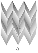
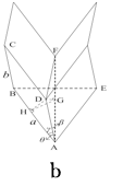

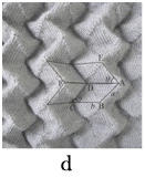
Figure 11 (a) Three-dimensional structure; (b) unit cell (c) Knit pattern (d) Stretched state of the knitted fabric.50

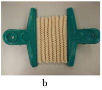

Figure 12 Auxetic fabric formed with the arrangement of face and reverse loops in rectangular forms. (a) Knitting pattern (b) fabric at the free state (c) fabric at the stretched state.52


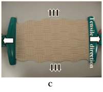
Figure 13 Auxetic fabric formed with the arrangement of face and reverse loops in horizontal and vertical stripes. (a) Knitting pattern (b) fabric at the free state (c) fabric at the stretched state.52
Auxetic knitted fabrics developed based on rotating rectangles: Several studies have revealed that an auxetic effect can successfully be induced by using rotating units such as squares,53 rectangles,54 triangles,55 rhombi56 and parallelograms.57 One such example based on rigid rectangles connected together at their vertices by hinges is demonstrated in Figure 14. Based on the same geometrical arrangement, an auxetic fabric was produced by Hong H et al.52 The knitting process is shown in Figure 14a. 15/2Nm 100% lamb’s wool yarn and Stoll CMS530 E3.5.2 machine was used to knit these fabrics shown in Figure 14b (free State) and 14c (stretched state). The knitting technique employed was partial-knitting to continuously knit individual rectangle units along the course direction and to make them connected together at their vertices. The partial knitting is a technique during which some needles are involved in knitting process, while others remain out of action but keep or do not keep the loops on them. The rectangle units were knitted in an interlock structure because an interlock structure has good structure stability. At the same time, the first knitting course on empty needles with an interlock structure can be easily carried out. In order to avoid unraveling and laddering, the binding-off technique was used to close the last course of each unit using a high power elastic rubber yarn. The elastic rubber yarn was also employed to knit the first course of each unit and to connect the neighboring units in the course direction. The use of elastic rubber yarn for connecting the rectangle units can increase the recovery capacity of the structure after release from extension. However, the fabric knitted only has the auxetic effect when extended in the course direction.
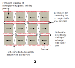


Figure 14 Auxetic fabric formed with rotating rectangles. (a) Schematic presentation of knitting process (b) fabric at the free state(c) fabric at the stretched state(d) Poisson’s ratio vs. strain 52.
It was also found that the trend for calculated and measurement Poisson’s ratio are totally opposite. Whereas the measured auxetic effect decreases with an increase of the strain, the calculated auxetic effect rises with increase of the strain and the auxetic effect calculated is much higher than that measured. As unlike in model the rectangles in knitted structures are not freely rotated around vertices under loading. The elastic yarns used to connect the rectangles can increase the axial deformation and the knitting yarn passing from one rectangle to the next rectangle limits the free rotation of the rectangles. In addition their shape can be easily changed to the parallelograms in knitted structure. Another problem is the slippage effect of the yarns in the knitted structure. All these lead to the different variation trends between the model prediction and measurement of the knitted fabric. Therefore, a simple geometrical model with rigid rectangles cannot be used to predict the auxetic effect of this kind of the fabric.
Auxetic fabrics developed based on reentrant hexagonal structure: A number of studies have revealed the potential of reentrant hexagonal geometries in order to induce the auxetic behavior. One such geometry is shown in Figure 15. When a reentrant hexagonal structure of this kind is stretched in the horizontal direction, the diagonal ribs 1–5, 5–2, 3–6 and 6–4 will move to the horizontal disposition, which leads to an increase of the distance between point 5 and 6 in transverse direction as a result, the auxetic effect in the whole structure is achieved. Hong H et al.52 successfully developed two kind of auxetic fabrics based on this geometrical arrangement. The first one was based on a real reentrant structure produced by using racking and intarsia techniques. The schematic of knitting process is shown in Figure 16a. 24/2Nm 100% acrylic yarn was used to knit the whole fabric structure shown in Figure 16b (free State) and 16c (stretched state). The zigzag shape for each pinstripe was realized through the racking process based on the Cardigan structure. The intarsia technique was used to knit each separated pinstripe with an individual yarn carrier. As explained previously, the interlock structure was used to connect the two neighboring pinstripes. The binding-off technique was used to close the last knitting course of each connecting band. The knitted fabric exhibited the auxetic effect when extended in the fabric forming direction.

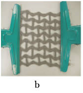

Figure 16 Auxetic fabric formed with real reentrant hexagonal structure. (a) Schematic presentation of knitting process(b) fabric at the free state(c) fabric at the stretched state.52
It was also found that the trend for calculated and measured Poisson’s ratio is totally opposite. Whereas the auxetic effect measured decreases with an increase of the strain, the calculated auxetic effect rises with an increase of the strain and the calculated auxetic effect is much higher than that measured. This phenomenon can be explained by the fact that in the calculation all sides of the re-entrant hexagon are assumed to be rigid and can be freely rotated around their connecting points. Conversely, in case of knitted fabric, the rotations around the connecting points are very limited due to loop connection. In addition, the length of each rib side of the fabric can be easily deformed under loading. All these lead to the different variation trends between the calculation and measurement of the real knitted fabric. The second auxetic fabric was a pseudo-reentrant hexagonal structure produced using sectional relief ridges in the combination with elastic yarn. The knitting process is shown in Figure 17a. The yarns used for the face side and back side were 24/2Nm 100% acrylic yarn and KN 20/70 DuPont Lycra yarn, respectively. The fabric is shown in Figure 17b (Free State) and 17c (stretched state). Unlike, the former reentrant hexagonal auxetic fabric, this fabric is a close structure. The reentrant hexagonal geometrical arrangement is achieved by both sectional relief ridges and float elastic yarns. While the section relief ridges form the upper and lower horizontal sides of each reentrant hexagon, two lateral sides effect is achieved due to shrinkage of the float elastic yarns on the back of the fabric. Different reentrant hexagonal geometrical forms could be obtained by changing the yarn float length and relief effect precisely. The knitted fabric exhibited the auxetic effect when extended in the wale direction only. It was also found that the trend for calculated and measured Poisson’s ratio is totally opposite. Whereas the auxetic effect measured decreases with an increase of the strain, the calculated auxetic effect rises with an increase of the strain and the calculated auxetic effect is much higher than that measured. This phenomenon can be explained by the fact that in the calculation all sides of the re-entrant hexagon are assumed to be rigid and can be freely rotated around their connecting points. Conversely, in case of knitted fabric, the rotations around the connecting points are very limited due to closed fabric structure. In addition, the length of each rib side of the fabric can be easily deformed under loading. The yarn slippage effect within the fabric structure can also increase the axial strain, which lowers the auxetic effect of the fabric. All these lead to the opposite variation trends between the calculation and measurement of the real knitted fabric.
Auxetic knitted fabrics developed based on double arrow head structure: Alderson K et al.58 developed auxetic warp knit textile structures using conventional wool yarn, based on triangular and double arrowhead geometries as shown in Figure 18a. The auxetic effect is produced due to hinging as shown in Figure 18a, leading to opening of the network of arrowheads. In order to realize the geometry of double arrowheads the fabrics were produced by employing two components, one as the auxetic component and the other as the stabilizing component. An 18-gauge machine was used Three types of fibres were used; two for the auxetic component were mono-filament PES (0.15mm) and mono-filament PES (0.25mm) and one for the stabilizing component was double coated lyrca and the stitch pattern was realized using four guide bars set. Firstly, the stabilizing component was knitted by using open loop stitches and the bases of the triangles knitted into the fabric using closed loop stitches as shown in Figure 18b. In another variation the first fibre of the stabilizing component was knitted in a tricot stitch with both closed and open stitches by using a set of four guide bars as shown in Figure 18c. This modification was aimed to produce a more isotropic fabric. It was reported that the stretching of the fabric is caused by the stretching of the stabilizing component and by rotation of the fibres of the auxetic component about their vertices. This rotation forces the re-entrant triangles of the auxetic component to take the shape of regular triangles, thus producing a negative Poisson’s ratio. The results for fabrics produced revealed that both fabrics exhibited conventional behavior, when tested in the x- and y directions but shown auxetic behavior when tested at_45° and +45° with values of (-0.02 and -0.13) for the first and (-0.22 and -0.13) for the second fabric. Second fabric with tricot stitches retains its auxeticity with all Poisson’s ratio values being negative. In addition, the fabric behaves linearly elastic up to the 10% of applied strain. The modulus of the fabric is defined by the modulus of the fibres of the stabilizing component and the resistance of the fibres of the auxetic component to the rotation about their vertices. The resistance is dependent on the knit pattern, the types of fibres used for the auxetic component and the relative properties of the fibres of the auxetic and stabilizing components. Therefore, modulus of the auxetic component and elasticity of the stabilizing components are critical considerations for this type of fabric. The modulus of the fibres of the auxetic component must be sufficiently high as compared to the resistance to rotation of that fibre about its vertices, which will force the shapes of the auxetic component to deform rather than stretching or buckling. Similarly, the elasticity of the fibres of the stabilizing component must be sufficiently high as compared to the resistance of the fibres of the auxetic component to rotation, which will make the stabilizing component to act as a return spring forcing the auxetic component back to its original shape when the stress on the fabric is removed. Therefore, the modulus of the fabric will be dominated by the modulus of the stabilizing component.
Glazzard M et al.59 had also translated double arrowhead auxetic geometry into a knitted fabric. They used weft knitting technology to produce auxetic knit structures that were a combination of several rows of face stitches and then several rows of reverse stitches. A 14 gauge Stoll CMS knitting machine and using multiple ends of Zimmermann Ultralastic 3772X-0010, a Lycra yarn with a single polyamide covering were used for this development. The knitting technique employed was a combination of relief and transfer structures as shown in Figure 19a. The relief pattern was chosen to impart three-dimensionality to the surface. As there are several rows of face stitch and then several rows of reverse stitch in the structure (purl rib). The V-shape was achieved by employing a transfer pattern, where a block of stitches was transferred one space to the right and on the next row another block of stitches was transferred one space to the left onto a central stitch between each block as shown in Figure 19b. This specific sample was chosen for repeat testing which showed interesting results exhibiting expansion in both X- and Y-axes. The images of produced samples were calibrated and measured to give the lengths of each transverse line as shown in Figure 19c as the vertical lines. The changes in each transverse measurement were observed. When the sample extended along Y-axis and transverse measurements were observed across the X-axis, the transverse measurement increases up to an extension of 50 mm and then the fabric starts to reduce in its transverse measurement again. Only an initial auxetic effect is achieved when the sample extended along the X-axis and expansion was measured along the Y-axis nevertheless, owing to the unfolding nature of the double arrow head stitch structure this becomes less capable of continuing to expand and, once unfolded completely it begins to behave as a conventional fabric.
Auxetic warp knitted spacer fabrics: Wang Z et al. adopted a novel geometrical structure that is based on parallelograms of same shape and size to engineer three-dimensional auxetic warp knitted spacer fabrics by using conventional yarn as shown in Figure 20a with negative Poisson’s ratio. In this 3D warp knitted spacer fabric two face layers are joined together by monofilament spacer yarns as middle layer.60−62 400D/96F non-auxetic polyester multifilament for face layer and 0.12mm non-auxetic polyester monofilament for middle layer were used to produce these auxetic warp knitted spacer fabrics on a double warp knitting machine equipped with six yarn-guide bars.
A post fabrication heat treatment process was also carried out in order to fix the geometrical configuration as designed. The fabric was based on the geometrical structure formed by linking together parallelograms of same shape and size to form a V as shown in Figure 20b. The repeating unit is shown in Figure 20c. It is formed with two parallelograms which are arranged in a V form. Each parallelogram was consisted of six ribs which are separated by connecting points of parallelogram with neighboring parallelogram. The ribs were named as short ribs and long ribs. Three geometrical parameters, i.e., length of the short rib l1, length of long rib l2, and angle formed between the short and long ribs ɵ, were used to determine the geometrical feature of the structure. Since the Poisson’s ratio is independent of material scale, therefore it was assumed that the fabrics with the similar geometrical configuration should have similar auxetic effect. Figure 21 shows that although the short and long ribs have different thicknesses, the geometrical configuration as above designed was successfully achieved in the structure of the face fabric layers. The auxetic effect of the structure mainly comes from the rotations of ribs around their connecting points when a tension is applied to the fabric structure. There is no doubt that under tension, the lengths of ribs could be changed. However, this change in auxetic effect is small if compared with the rotations of ribs. The geometrical parameters have an obvious effect on the auxetic behavior. The closer fabric structure will have the higher auxetic effect. The auxetic behavior of this auxetic warp knitted spacer fabrics depends on the tensile direction and value of tensile strain. The highest auxetic effect is obtained when stretched in the weft direction, and the lowest auxetic effect is obtained when stretched in the warp direction. The auxetic effect decreases with increase of the tensile strain. As one of the advantages of auxetic fabrics over conventional fabrics is their excellent shape fitting ability on a curved surface due to the formation of synclastic curvature under bending condition. This is very important for the fabrics to be molded into different shapes for garments or composite parts. In order to check this shape fitting ability, both non-auxetic and auxetic warp-knitted spacer fabrics were placed on a spherical surface formed with a diameter of 100mm. It was observed that the auxetic warp knitted spacer fabric perfectly covers the spherical surface due to the formation of the dome shape indicating that it has much better shape fitting ability than conventional spacer fabric which has a saddle shape. This ability makes them very suitable for various applications where shape fitting is highly required. One of the problems to be encountered by an auxetic fabric is the loss of its auxetic effect under repeating tensile loading due to imperfect elasticity of textile materials. That will affect its performance during repeated use. The auxetic effect of warp knitted spacer fabrics tends to be stabilize after the second tensile cycle and about 65% of its auxetic effect is retained even after 10 cycles of extension. One possible solution to increase the retention ability of auxetic effect of auxetic warp knitted spacer fabric might be the use of yarns with high elastic recovery ability to knit face fabric layers.

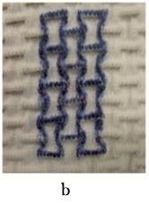
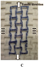
Figure 17 Auxetic fabric formed with pseudo-reentrant hexagonal structure. (a) Schematic presentation of knitting process (b) fabric at the free state (c) fabric at the stretched state.52
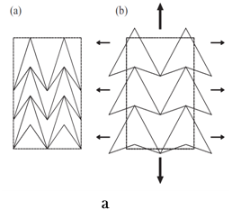
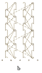
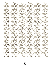
Figure 18 (a) Triangular or double arrowhead auxetic topology (b) stitch pattern for fabric with open and closed loop stitches (c) stitch pattern for fabric with tricot stitches.58
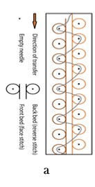
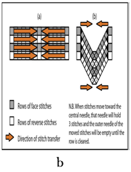
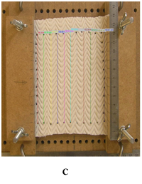
Figure 19 (a) Diagram showing stitch structures that can be altered to produce auxetic effects.(b) Diagram showing movement of the stitches in the pattern and the resultant deformation of the course shape to give the V-shped effect (c) Image showing sample in test frame and Cell^B software marking 11 transverse measurements.59

Figure 20 Sketch of geometrical structure.60
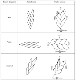
Figure 21 Realization of auxetic effect due to rotations of ribs.60
Auxetic woven fabrics: An auxetic woven textile structure to be used as reinforcement for composite was produced by Miller W et al.44 they used a double helix yarn. A twisted ultra-high molecular weight polyethylene (UHMWPE) fibre (220 dtex) was used as the wrap material and the core material used was a polyurethane (0.64 mm diameter) core with an approximate wrap angle of 70° for production of DHY. The textile structure was woven using a plain weave, with the weft being the DHY and the warp being a meta-aramid fibre (approx 475 dtex). The DHY yarn was woven out of register to maximize the auxetic behavior as shown in Figure 22. It was observed that the yarns in the woven fabric were able to overlap each other out of plane, causing an out of plane negative Poisson’s ratio and losing the in plane auxetic behavior.
However, on stretching due to the fibres overlapping the out of plane thickness of the sample increased. Therefore, an out of plane negative Poisson’s ratio but an in plane positive Poisson’s ratio of 0.06 was demonstrated. In order to prevent the out of plane overlapping the sample was retested whilst having the thickness constrained between two glass plates at constant separation. The extra constraint provided by the plates prevented the yarn from overlapping and a negative Poisson’s ratio of _0.1 was observed, as shown in Figure 23. The spike in the graph appeared is due to vibration of the camera equipment used in the video extensometry. The limitation of this fabric is that only out of plane negative Poisson’s ratio is achieved for this fabric. However, different woven structures which can provide thickness constraints (for example multilayered structures with outer layers as thickness constraints and central layer comprising of HAY yarns) can be investigated in order to achieve an in plane negative Poisson’s ratio. Additionally, woven structures other than plain weave can also be explored to observe the weave effect on the out of plain negative Poisson’s ratio. Wright JR et al.46 produced auxetic woven fabrics using helical auxetic yarns (HAY). Two types of bandage like woven fabrics were produced. The first fabric named as “Fabric-B” as shown in Figure 24 was produced by using HAY in the warp direction. The HAY was consisted of a UK Sewing Services EL/M128 1mm diameter covered rubber core, and a Rex H Perkins20 ring spun PET 16/1 (630dtex equivalent) wrap. The wrap angle of 45 degrees was chosen. A 2-ply plain woven narrow fabric having width of 20mm was produced. The warp density was 26 warp ends inserted at 1end/dent. 1100dtex natural, multifilament PET yarn was used as weft with a density of 14picks/inch. The second fabric named as “Fabric-C” shown in Figure 25 was also produced by using HAY in the warp direction. The HAY was consisted of Stretchline21 covered rubber 3-end (2 wrap, 1 core) 0.18mm core, with a 2/ 110/34 (2 ends of 34 filaments, 110dtex) textured nylon wrap. The wrap angle of 45 degrees was used. A single-ply plain woven narrow fabric having width of 25mm was produced. The warp density was 48 warp ends. 550dtex PET was used as weft with a density of 12picks/inch. It was aimed to produce fabrics which gave a drape and handle more corresponding with conventional bandages. Tensile tests were performed using a Lloyd Instruments’ EZ20 testing machine. In order to determine strain at different extension intervals images were captured at corresponding time intervals by using a high-resolution CMOS camera (Edmund Optics EO-5012C, 4.9M pixel) and Image J public domain image processing software. This procedure is described in detail by Sloan M et al.45 The effective diameter of the HAY at any given strain was determined by producing a negative binary image by using the Image J Line Width variable in conjunction with a calibrated pixel count, and in that way the Poisson’s ratio of the HAY (or fabric) was estimated.
The Fabric B exhibited a negative in-plane Poisson’s ratio in the strain range 15–40%, reaching a maximum negative value of –0.1 at approximately 32% strain. The pore-opening effect was also measured by analyzing the images. The open area of the fabric-C for a range of strains was measured by loading a series of images into Image J software. The Image/ Threshold facility was used to identify and mark the open areas and the Measure facility used to report the percentage of open area as shown in Figure 26a. The pore-opening effect in Fabric C at approximately 30% strain was observed. No direct association between load and open area was found. Probably, this is due to a range of factors, including the out-of-plane (thickening) effects, crimp of warp and weft, warp tension, location of weft yarns and lack of homogeneity of the fabric. Fabric-C exhibited positive Poisson’s ratio for all strains. This is largely a function of the choice of weft material and weave geometry, allowing warp yarns to overlap, thereby causing a thickening of the fabric and thus an out-of-plane negative Poisson’s ratio as shown in Figure 26b. It would be expected that a more elasticated weft or higher weft crimp can give rise to a negative in-plane Poisson’s ratio for the fabric. It was also observed that the distribution of the pores is inhomogeneous with more opening in the center of the fabric due to greater density of yarns near the edges. It is also possible to exploit the pore opening effect to generate a color change for indicative or aesthetic purposes, for example by inserting a substrate of a different color beneath an exterior auxetic layer. Fabric B was modified by removing the binder thus, creating a tubular fabric which contained red filler yarns as shown in Figure 26c, under 0 N and 80 N tension respectively. Under tension the red color of the filler is exposed through the open pores of the fabric. However, both of the fabric has totally different structures as fabric B is a 2-ply plain woven narrow fabric while, fabric C is a single ply plain woven fabric. Therefore, it is obvious that they may have different behavior as structure is an important geometrical parameter which greatly influences the behavior of fabric in terms of lateral expansion or contraction. Therefore, it is very difficult to idealize the suitable material and weave structure for ideal pore opening effect and for auxetic effect by study of these two fabrics only. Further investigation in terms of woven structural effects, material effect and effect of number of plies on the negative Poisson’s ratio and pore opening must also be investigated for better understanding of relationship among different parameters and negative Poisson’s ratio. Monika V et al.63 used helical auxetic yarn in weft direction and poly propylene yarns in warp to produce auxetic woven fabrics. They have used hand weaving loom to produce three kinds of woven fabrics with the HAY in weft direction. The weave pattern chosen were plain, 2/2 twill and 3/5(3) satin pattern. Two ply multifilament polypropylene yarn of 72 Tex was used as warp with a density of set of 2 threads/cm. the HAY was consisted of two types of “single threads. The core was industrially produced polyester elastic band having fineness of 922 Tex and two ply polypropylene multifilament yarn of 72 Tex with preventive twist for wrap. The weft density used was set 9 threads /cm. the fabrics were tested on dynamometer In stron and images were captured at interval of every 10th second by using a CCD camera. The image analysis NIS Elements was used for analysis. Four points at a distance 1 cm from each other were marked in the middle of each 5cm×20cm sample as shown in Figure 27. Finally Poisson's ratio values for the concrete deformation were calculated. Figure 28 illustrates the changes occurred in the structure of three fabrics due to deformation process at about 40% of their deformation during the straining process. Plain woven fabric along with twill woven fabric exhibited most auxeticity and satin pattern is statistically significantly less auxetic. It was also observed that less auxetic behavior caused less porosity. Auxetic behavior of woven fabrics is likely to be influenced by floating threads in a woven structure. Longer the floating threads less will be the auxetic behavior exhibited due to the fact that they have more space in the woven structure for their transversal deformation. Conversely, in the woven structures with short floating threads the threads have to apply pressure on nearby threads to transversally deform themselves and finally the woven fabric extends transversally. As concluded by the authors that “different auxetic behavior of three observed patterns doesn't statistically significantly manifest in pores' parameters,but is obvious on porosity”. It is of vital importance to consider the weave structures and balance of floating length (which means the float length in warp and weft direction are equal or not) while comparing the results of above three fabrics. As far as weave structure is concerned no doubt all the fabrics have different weave structure and float length.
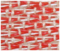
Figure 22 Woven fabric made of DHY yarn.44
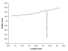
Figure 23 Graph of longitudinal against lateral strain for single DHY woven Fabric textile under load constrained between two plates.44

Figure 24 Fabric B comprising helical auxetic yarn as warp fibres (horizontal).46

Figure 25 Fabric C comprising helical auxetic yarn as warp horizontal). (The fibrous nature of the textured nylon wrap obscures the HAY structure).46
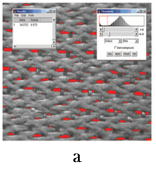
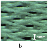
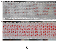
Figure 26 (a) Measuring the proportion of open area of fabric at a given strain (b) Fibers overlap, giving rise to negative Poisson’s ratio out-of-plane and a consequent reduction in in-plane negative Poisson’s ratio (c) Prototype color-change fabric B; a) 0 N tension, b) 80 N.46
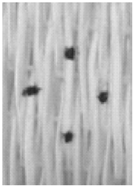
Figure 27 Placement of four points for Poisson's ratio evaluation.63

Figure 28 Woven fabrics: (a) plain, (b) 2 /2 twilland (c) 3 /5 (3) satin pattern at 40% deformation.63
But, the symmetry of floating length is also different. In case of plain and twill weaves the floating length is equal both in warp and weft direction. On the other hand, floating length in warp and weft direction is not equal in case of chosen 3/5(3) satin weave. Therefore, it cannot be concluded that the weave structure alone is responsible for this behavior of all three fabrics. If the aim is to study the effect of weave structure only then 4/1(3) satin is more suitable choice as this structure has almost equal floating length in warp and weft directions.
Auxetic non-woven fabrics: Verma P et al.64 reported that it is possible to induce out-of-plane auxetic behavior in needle-punched nonwovens. They obtained needle-punched nonwoven fabrics from Ten Cate Protective Fabrics (Senoia, Georgia, USA). These fabrics were composed of virgin polyethylene terephthalate (PET) crimped staple fibre The carding direction and machine direction were the same for all samples. The total number of needle penetrations per square inch was likely to be considerably larger. The technical data of the obtained needle-punched nonwoven fabrics is shown in Table 1. In order to produce heat-compressed samples a Carver1 auto series (model no. 4389) bench top press was used to compress both nonwovens NW1 and NW2 in the thickness direction at 2.45 MP a pressure for 20h at a temperature of 70°C. After 20h, heating was discontinued and the fabric samples were allowed to cool under full pressure for another 4 h up till the ambient temperature, i.e., after 24 h of total compression, it was removed from the press.
The compressed samples were also prepared by compression without using heating on the same press, i.e., at room temperature. In this case, they were compressed under the same pressure as above for 24 h and then removed from the press as shown in Figure 29. Uniaxial tension experiment was performed on each sample and the thickness values were observed during extension for as-received, compressed, and heat-compressed samples. The instantaneous Poisson’s ratio values based on these data were calculated at each ith strain level by using instantaneous true strain as shown in Eq. (1)
(2)
Where and denote the measured specimen length and thickness values, respectively, at the given ith strain level and and denote their values at the previous strain level. That is why it is called “instantaneous” Poisson’s ratio. Figure 30 shows the values of instantaneous Poisson’s ratio with respect to axial strain for as-received, compressed, and heat-compressed needle-punched nonwoven specimens tested along the machine direction. The as-received nonwoven samples showed a decrease in thickness with extension and positive Poisson’s ratio varying between 0.1 and 0.5, mostly around 0.2 for NW1 and NW2. While, in the case of compressed samples, the thickness was increased rapidly up to 40% strain after which the thickness began to decrease until sample failure at 130% strain. The value of instantaneous Poisson’s ratio obtained was -0.9 in the initial strain regime which was decreased with increasing strain. After the maximum thickness was achieved at 40% strain the Poisson’s ratio is positive as shown in (Figure 30a) (Figure 30b).
Sample ID |
Fiber Denier |
Fibre Length |
Areal Density oz./yd2 |
Mean thickness (mm) |
Fiber Columns by the Ceedle Penetrations /in2 |
NW1 |
6 |
3 in. |
20 |
4.40+0.14 |
280 |
NW2 |
6 |
3in. |
30 |
5.32+0.25 |
280 |
Table 1 Technical data of non-woven samples

Figure 29 Diagram showing the processing treatment of as-received samples in a Carver1 hot press to produce compressed” and “heat compressed” samples.64
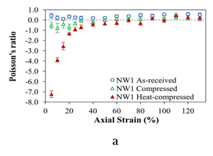
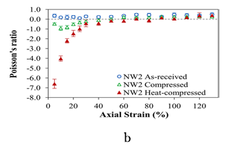
Figure 30 (a) Variation of instantaneous Poisson’s ratio with respect to axial strain for as-received, compressed, and heat-compressed NW1 (b) NW2 needle-punched nonwoven specimens tested along the machine direction. Error bars represent the standard deviation in Poisson’s ratio at each data point as calculated over five specimens of each type.64
In case of heat-compressed fabrics, both NW1 and NW2 show a remarkably steep increase in thickness when stretched, especially in the initial 30% strain region. Even after 40% strain, the specimens continued to increase in thickness, but at a slower rate, until they attained their maximum thickness at approximately 80% axial strain, in both cases and failed at about 130% strain as shown in (Figure 30a) (Figure 30b).The instantaneous Poisson’s ratio for heat-compressed samples is highly negative at small strain values due to rapid increase in thickness. The Poisson’s ratio was -7.2 for NW1 and -6.6 for NW2, corresponding to 5% strain. Similar to compressed samples, the Poisson’s ratio for heat-compressed samples became positive after the specimen had attained its maximum thickness (approximately 80% strain) as shown in (Figure 30a) (Figure 30b).
As the fibre columns in non-woven fabric are not highly rigid also some are severely deformed by the processing conditions. Therefore, they never return completely to their original near vertical state. In case of treated fabrics locally bent fibres that are constrained to lie over a given fibre and then below another proximal fibre is another important structural feature which contributes to the auxetic response. When stretched this bent fibre pushes the fibres above and below causing an increase in fabric thickness. However, this phenomenon is only possible if the structure is dense enough. In case of dense structure local forces are transferred to neighboring bent-fibre configuration, and fibres may offer some resistance to slippage due to frictional contacts. Meanwhile, the heat compressed samples are of a denser structure as compared to the compressed (only) samples and the fibre columns are inclined at larger angles in heat-compressed fabrics, a greater auxetic response is therefore achieved for them. This process of producing auxetic non-woven fabrics and the described phenomenon may be used as guideline for development of further non-woven material and structures. Some other factors including the nature of fibre–fibre entanglements, fibre curl and crimp, fibre staple length, fibre modulus and fibre column rigidity, needle-punching parameters, etc. may also be responsible to influence the auxetic response. These factors together with the phenomenon of auxetic response must also be investigated in order to develop and ideal auxetic non-woven material.
Auxetic textile structure for composite reinforcement: Developments in auxetic materials production have made it possible to produce auxetic fibre reinforced composites. Miller W et al.44 reported that an auxetic composite can be produced by using a woven auxetic fabric made of auxetic yarns. The reinforcement for an auxetic composite can be made using a double helix yarn (DHY). The auxetic behaviour of DHY yarns can be reserved into a woven fabric if the pitch levels between adjacent yarns in the fabric and material properties are optimized. Therefore, the DHY yarns should be woven out of register to maximise the auxetic behaviour. Further, if a matrix with a suitable matched modulus is selected, the auxetic composites can also be engineered by using woven fabric made of DHY yarns. A double layer auxetic composite with an approximate PR of -0.1 can be produced using the woven fabric reinforcement manufactured from DHY yarn. The DHY yarn has a PR of - 2.1. The reinforcement is a plain woven fabric. The DHY yarn is used as weft and Meta aramid yarn of approximately 475 dtex linear densities is used as warp. The matrix material for the composite samples selected is silicone rubber gel (Dow Corning 3-6512, 2part elastomer). There should be a notable difference in stiffness between the three components, i.e. the wrap is an order of magnitude stiffer than the yarn, which in turn is an order of magnitude stiffer than the matrix. It is important to consider that a single layer composite will not be auxetic, most probably the constraint imposed by the matrix will not be sufficient to prevent the fibres overlapping out of plane. The auxetic effect in the composite is likely to be due to the extra constraint provided by the additional layers of DHY textile network. It is usual for composites to be multi layered.
3-D Auxetic textile structure for composite reinforcement: A novel 3-D auxetic (negative Poisson’s ratio) textile structure for composite reinforcement which shrinks when compressed, was produced by Ge Z et al.65 They combined the non-woven and knitting technology with conventional yarns and produced some novel 3D auxetic fabric reinforcements that could be utilized as preform to produce auxetic composites. The novel 3D auxetic fabric structure as shown in (Figure 31a) composed of three yarn systems, i.e. weft yarns, warp yarns and stitch yarns.
The weft yarn and warp yarns are not interlaced as is the case in woven fabric preforms and therefore not crimped. Instead, they are placed at 90° upon one another and held in position by a third yarn. The warp yarns are placed one in and one out, and the positions of all of the warp yarns in two neighbouring layers are alternated by half yarn spacing. The third yarn is placed through the thickness direction and serves as stitching yarn as shown in Figure 31a. When the structure is compressed through the thickness direction the weft yarns will get crimped, resulting in shrinkage of the structure in the weft directions. Since the weft yarns are fully arranged, the shape of the warp yarns remains unchanged under compression and the size of structure will not change in the warp direction as shown in Figure 31b. Therefore, under compression the structure will exhibit auxetic behaviour in the weft direction and zero Poisson’s ratio in the warp direction. The phenomenon of compression and shrinkage in the weft direction can better be demonstrated with help of Figure 32. Figure 32a shows a repeating unit of the structure outlined by breaking lines. Figure 32b demonstrates the condition under compression. The auxetic effect is mainly produced due to the spaces between the warp yarns. This may result in the reduction of the stability of the structure. As this 3D auxetic structure is developed as composite reinforcement, the compressible matrix will be filled in the spaces of the structure to make the composite. Therefore, the stability of the composite structure will be ensured. To fabricate this 3D negative Poisson’s ratio fabric structure, a special textile manufacturing process that combines both the non-woven and knitting technologies has been proposed. It is notable that if the same type of yarn is used for both the weft and warp yarns, the auxetic effect of the structure would not be very obvious. The weft yarn should be flexible and the warp yarn should be rigid. An elastic yarn with diameter lesser than warp and weft yarns can be used as the stitching yarn for better binding effect. The elasticity of the stitch yarn may be selected in such a way that the whole structure can be held by stitches without causing the obvious deformation of the weft yarns at the initial state. It is also important that under the action of the stitch yarn tension, the weft yarns cannot be kept totally straight at the initial state. So this initial effect should be taken into consideration during the analysis of the structure. The auxetic effect of the structure is not constant; it increases as the compression strain increases. The geometrical model can be used to predict the auxetic effect of the structure with given structural parameters. Critically, it is important that the warp yarns must be placed one in and one out, and the positions of all of the warp yarns in two neighbouring layers must be alternated by half yarn spacing. The suitable selection of structural parameters is also an important consideration in order to achieve the desired auxetic effect. The high yarn fineness ratio between the warp and weft yarns must be used to obtain a high auxetic effect of the structure when other structural parameters are kept constant.
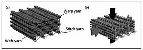
Figure 31 Three dimensional auxetic textile structure (a) Initially (b) Under compression.65
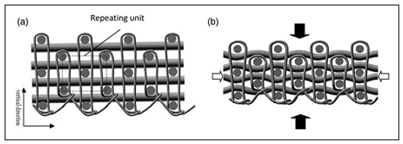
Figure 32 The cross section of 3-D auxetic structure (a) Initially (b) Under compression.65
Potential applications of auxetic textile materials: The auxetic materials have many potential applications like; if the pore opening in the auxetic woven fabric structure can be exploited. This behavior makes auxetic fabrics very attractive for some special applications, such as filtration in which pore opening size of filter can be controlled by tension.5,26, Auxetic materials can also be used for vibration damping, shock absorbency the pore opening effect can also be utilized in bomb blast curtains which can open a large number of pores under tension allowing the shock wave through but leaving the curtains intact to catch glass and other debris and smart bandage in which applied drugs can be automatically delivered like the dental floss with in-built drug release.36 By exploiting the ability to open pores in the fabric structure there are possible applications in fluid transfer, such as drug delivery or exudate removal.45 Helical auxetic yarns made of optical fibre can be used as sensors and moisture sensitive auxetic materials for functional garment were also suggested.42 In addition to helical auxetic yarn structure and its made fabrics, composites reinforced by auxetic yarn made of carbon fibre44 and woven fabric made of auxetic yarn46 were also investigated by Miller et al. Their studies demonstrated that such composites exhibit auxetic behavior as well. Auxetic materials can also be used as core materials in curved sandwich panel composite components, radome applications, directional pass band filters, micro-electro-mechanical system (MEMS) devices, seat cushion material and fastening devices. Auxetic composite laminates and composites containing auxetic constituents also provide enhancements in fracture toughness, and static and low-velocity impact performance that suitably demonstrate potential in energy absorber components. Due to property of lateral expansion auxetic fabrics can be used as clothing for periods of growth such as maternity clothing and child development and possibilities for promoting clothing longevity due to adaptability in sizing,under garments and shape wear, like bra cups, under wears and leggings and sportswear where transverse shrinkage, due to stretch, might be problematic other applications may include such as performance costumes, interactive art installations and textiles as a therapy through texture, aesthetic and interaction.50 As the porosity of auxetic fabrics increases they can be used in clothing where good oxygen transportation and sweat evaporation is required. The color change indication under tension can be incorporated in fashion clothing.46 Auxetic fabrics engineered with optical properties can be used to produce the green-house effect. Auxetic textile materials can also be used in applications including geo textiles, reinforcements in advanced composites for aerospace and auto motive sectors and personal and sports protective garments such as bulletproof vests and batting gloves.36 The auxetic fabrics have an excellent shape fitting ability. This ability makes them very attractive for various applications where shape fitting is highly required.62
From this study it can be concluded that, different auxetic fabrics have been produced based on two approaches. Firstly, the use of auxetic fibre or yarn to fabricate the auxetic woven as well as knitted fabrics. The demerits of this approach are the availability of very few auxetic fibres and yarns. Secondly, to fabricate the auxetic fabrics from conventional yarns, as the auxetic behavior is purely linked with the geometrical arrangements of structural units. Further, due to the limitations like low structural stability, low elastic recovery, higher thickness and difficulty in the fabrication because of their complicated geometrical structures, auxetic knitted structures cannot be successfully used in garment manufacturing but they have other potential applications including, vibration damping, shock absorbency and reinforcement for composites. In order to develop auxetic fabrics that could be used for clothing it is essential that the thickness and structural stability must be taken into account. Additionally, the technology to develop the auxetic materials specially fabrics on larger scale needed to be developed as most of the fabrics up till today are produced on laboratory scale. The area of modelling auxetic materials is also unaddressed; research must be carried out to develop modelling techniques for auxetic materials so that the properties of auxetic materials can be optimized and tailor made according to specific requirements before actual production of fabric. Undoubtedly, auxetic textile materials have great potential to be classified as smart and intelligent textiles and to be incorporated in to real life applications but it is a matter of continuing research.
None.
Author declares there is no conflict of interest in publishing the article.

©2017 Hu, et al. This is an open access article distributed under the terms of the, which permits unrestricted use, distribution, and build upon your work non-commercially.