
Review Article Volume 5 Issue 2
A computational approach to profile generation of different shedding cams and an analysis of their kinematic characteristics
Anindya Ghosh
Regret for the inconvenience: we are taking measures to prevent fraudulent form submissions by extractors and page crawlers. Please type the correct Captcha word to see email ID.

Associate Professor in Textile Technology, Government College of Engineering & Textile Technology, India
Correspondence: Dr. Anindya Ghosh, Associate Professor in Textile Technology, Government College of Engineering & Textile Technology, 4 Cantonment Road, Barrack Square, Berhampore, West Bengal, India-742 10, Tel 91-9474323437, Fax 91-3482-252809
Received: January 25, 2018 | Published: April 15, 2019
Citation: Ghosh A. A computational approach to profile generation of different shedding cams and an analysis of their kinematic characteristics. J Textile Eng Fashion Technol. 2019;5(2):126-132. DOI: 10.15406/jteft.2019.05.00193
Download PDF
Abstract
In this study, a computational plotting of different types of shedding cam profiles has been endeavored. Various shedding cams like linear, simple harmonic, parabolic, cycloidal etc. for designing plain and twill weave shave been considered. A critical analysis on the kinematic characteristics for different types of cams suggests that the simple harmonic and cycloidal cams outperform parabolic and linear cams for high speed weaving.
Keywords: cam profile, cycloidal, follower motion, kinematics, simple harmonic, shedding, weave
Introduction
Cam-follower mechanism converts a rotary motion into a linear reciprocating motion. The input of cam rotary motion transforms into output as a follower motion consisting of rise, dwell and fall. The transition of dwell with rise and fall is an important aspect of cam design since the follower must go from a velocity and acceleration of zero into a motion with specific velocity and acceleration. The rise and fall of the follower have many possible motions such as linear, simple harmonic, parabolic, cycloidal etc.1,2 The design of the cam profile ultimately determines the pattern of follower motion with desired displacement, velocity, acceleration and jerk.
For excellent loom performance, the cams should be properly selected.3,4 The appropriate choice of cam is more enhanced in case of high speed looms which are required to maintain a high level of performance. Mali et al.5 used finite element approach to perform the design optimization of cam and follower mechanism. Patel6 made a critical review on the design of cam and follower. Desai & Patel7 made a computer aided kinematic and dynamic analysis of cam and follower.
This study endeavors the computational plotting of different types of shedding cam profiles. A comparison of different types of cams with respect to their corresponding kinematics has also been discussed in this work.
Designing of shedding cam profile
A cam is a rotating machine element which offers rectilinear reciprocating or oscillating motion to another element known as follower. Conventionally, in a cam-follower system, the cam is generally operated at a fixed rpm and the motion characteristics of the follower are estimated once the cam displacement curve is designed. The cam profile is the shape of the contoured cam surface by means of which motion is communicated to the follower. In reality the cam profile can be better visualized by imagining the cam to remain stationary while the contact points between cam and follower revolves round the cam in the opposite sense of the actual cam rotation. With such an idea the locus of the successive touching points of tangents with the follower yields the cam profile.8,9 The position of the follower depends on the centre-to-centre distance between cam and follower (ρ) and angle of the cam shaft rotation () as depicted in Figure 1. Therefore, if
describes the locus of the follower surfaces, the coordinates of cam profile are obtained by solving the following two equations
(1)
(2)
Where
is the partial derivative with respect to and .For a cylindrical follower with radius as shown in Figure 1, the locus of its surface is given by:
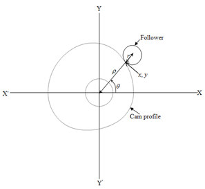
Figure 1 The coordinates of cam and follower.
(3)
From which the partial derivative gives
(4)
Where
is the derivative of
. By solving Equations (3) and (4), the x, y coordinates of cam profile are obtained which are expressed by:
(5)
(6)
The two solutions of x and y correspond to the inner and outer profiles of cam, respectively. In this study, only inner profile has been considered which eventually yields the shape of negative cam profile.
During the rise and fall regions of the follower,
is varied according to the shape of the cam profile and it remains constant during the dwell position. The expression of in Equations (5) and (6) is substituted by:
(7)
Where S is the follower displacement with respect to the angle of cam shaft rotation. For a complete rotation of cam, is ranging from k to
, where is the distance from the cam centre to the nearest position of the follower centre and h is the maximum lift of the follower. In this study the values of k, h and the crank shaft rpm are considered as 4cm, 5cm and 240rpm respectively. There are many possible motions such as linear, simple harmonic, parabolic, cycloidal etc. for the follower during its rise and fall. The equations of follower displacement (S) with respect to the angle of cam shaft rotation for (
) various types of motion are given in the Table 1 where m, p and c are the constants.
Types of motions |
Follower displacement equation |
Linear |
|
Parabolic |
|
Simple harmonic |
|
Cycloidal |
|
Table 1 Amplitude in mill volts of the Lead-1 of electrocardiography in sheep
*Significant (P≤0.05); NSNot significant (P>0.05)
To accomplish the computational plotting of the cam profile, some basic weaves like plain and twill have been chosen with one third dwell period. Different types of basic motions such as linear, simple harmonic, single parabolic, double parabolic and cycloidal for the heald shaft during its lifting and lowering movement have been considered in this study.
The profile of each cam consists of four parts, namely lifting, dwell at top position, lowering and dwell in bottom position. Table 2 & Table 3 depict the actual lifting and lowering equations of the follower displacement (S) corresponding to different cams used in the shedding operation for plain and
twill weaves, respectively. The values of S during the dwell at top and bottom positions are remaining constants which are h and 0, respectively. For designing a specific type of cam profile, firstly the corresponding equations of S during the periods of lifting, dwell at top position, lowering and dwell at bottom position are replaced in Equation 7. Then the Equations 5 and 6 are used to find the coordinates of x and y over a range of
from 0 to
radians for obtaining the cam profile. MATLAB coding was used for the purpose of plotting.
Cam type |
Lifting of follower
|
Lowering of follower
|
Linear |
|
|
Simple harmonic |
|
|
Single parabolic |
|
|
Double parabolic |
|
|
Cycloidal |
|
|
Table 2 Lifting and lowering equations of follower displacement for different cams used in plain weave design
Cam type |
Lifting of follower
|
Lowering of follower
|
Linear |
|
|
Simple harmonic |
|
|
Single parabolic |
|
|
Double parabolic |
|
|
Cycloidal |
|
|
Table 3 Lifting and lowering equations of follower displacement for different cams used in
twill weave design
Figure 2 illustrates the profile of the various types of shedding cams used in plain weave design. The profile of each cam depicted in Figure 2 consists of four parts, namely the rise from 0 to radian, the dwell from to radian, the fall from to radian and another dwell from toradian.
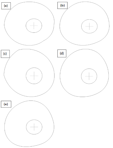
Figure 2 Profiles of various cams used in plain weave design: (a) linear, (b) simple harmonic, (c) single parabolic, (d) double parabolic, (e) cycloidal.
The profiles of different types of shedding cams used in twill weave design are shown in Figure 3 where profile of each cam is consisting of the rise from 0 to
radian, the dwell from
to
radian, the fall from
to
radian and another dwell from
to
radian.
The profiles of different types of shedding cams used in
twill weave design are shown in Figure 3 where profile of each cam is consisting of the rise from 0 to
radian, the dwell from
to
radian, the fall from
to
radian and another dwell from
to
radian.
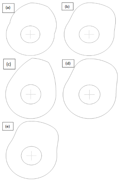
Figure 3 Profiles of various cams used in 3/( 1) twill weave design; (a) linear, (b) simple harmonic, (c) single parabolic, (d) double parabolic, (e) cycloidal.
Kinematics of follower motions for different cams
The velocity, acceleration and jerk equations can be obtained by differentiating the displacement equation with respect to time (t) by once, twice and thrice respectively. Therefore, the velocity, acceleration and jerk of the follower are given by
,
and
, respectively.10 Figures 4 and 5 depict the displacement, velocity, acceleration and jerk plots of follower for different types of cams used for the plain weave shedding operation.
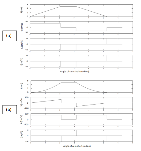
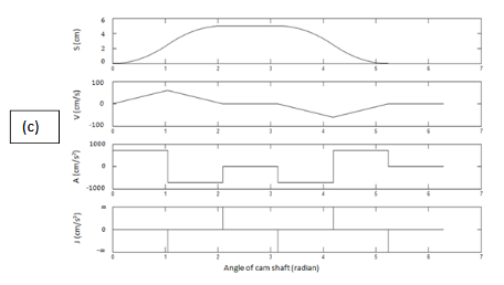
Figure 4 Displacement (S), velocity (V), acceleration (A) and jerk (J) plots of follower for different types of cams; (a): Linear, (b) Parabolic, (c) Double parabolic.
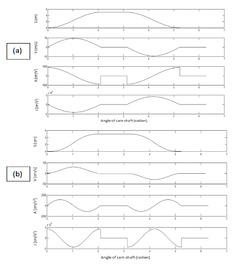
Figure 5 Displacement (S), velocity (V), acceleration (A) and jerk (J) plots of follower for different types of cams; (a): Simple harmonic (b) Cycloidal.
The linear cam produces constant velocity but the main problem associated with this cam is that at the start and end of the dwell period, the acceleration and jerk become infinity, since the velocity and acceleration changes its direction in an infinitely short time. Hence this cam cannot be suitable at high speed.
The single parabolic cam produces linear velocity and constant acceleration during the lifting and lowering. During the end of the lifting motion and start of the lowering motion, the follower velocity reaches maximum. Similar to the linear cam it shows infinity jerk at the beginning and the end of the dwell period because the acceleration changes its direction in an infinitely short time. Thus it creates trouble in high speed application.
In case of double parabolic cam the velocity of follower during its rise and fall is represented by two straight lines having opposite slopes. The velocity of follower increases linearly, reaches maximum at the mid position and then start to fall linearly during the lifting and lowering movements but it becomes zero during the beginning and end of the dwell periods. As a result of that the acceleration changes abruptly from positive to negative direction and vice versa during the lifting and lowering motion of follower. This creates infinite jerk as the acceleration changes its direction in an infinitely short time. Hence this cam is not also desirable in high speed application.
For a simple harmonic cam, velocity of the follower during its rise and fall represents by a sine curve while the acceleration of the same represents a cosine curve. The follower velocity remains zero at the start and end of the rise and fall which ensures a suitable linking with the dwell by means of smooth transition at the junction of zero velocity. As a consequence acceleration and jerk remain finite. The nature of the jerk curve is in a direction opposite to the velocity curve. Thus it is quite suitable cam for high speed application.
A cycloid can be defined as the trajectory followed by a point on the circumference of a circle which is rolling without slipping on a straight line. For a cycloidal cam, acceleration and jerk of the follower are represented by sine and cosine curves, respectively. Both the velocity and acceleration of follower are remaining zero at the start and end of the rise and fall. Therefore, a cycloidal cam ensures a perfect linking with the dwell caused by the smooth transition at the junctions of zero velocity as well as acceleration. Consequently, the jerk produces a non-infinite pulse. This cam is also suitable for high speed application.
Comparison of various types of shedding cams
The lifting motion of the follower corresponding to different types of shedding cams has been considered for the purpose of comparison. Figure 6 and Figure 7 depict the displacement, velocity, acceleration and jerk plots of the follower during its lifting motion.
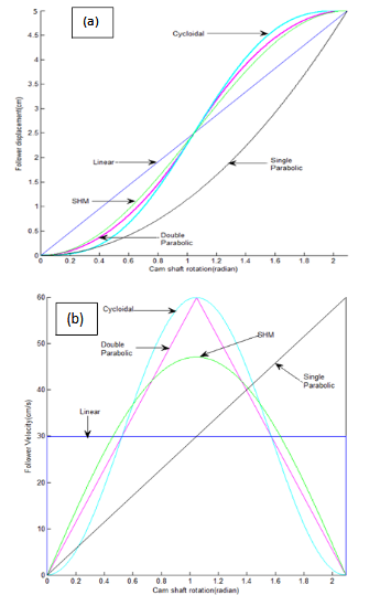
Figure 6 Displacement and velocity plots of follower for different cams during the lifting motion; (a) Displacement plots (b) Velocity plots.

Figure 7 Acceleration and jerk plots of follower for different cams during the lifting motion; (a) Acceleration plots, (b) Jerk plots.
It is quite obvious from the Figure 6a that the follower displacement diagram of the linear cam is a straight line whereas in case of single parabolic cam it is parabolic and concave towards the displacement axis. In case of all but the single parabolic cam, the follower reaches the half of the displacement at the same time. The follower displacement of the simple harmonic, double parabolic and cycloidal cams shows a sigmoidal type of curve and the second half of the displacement curve during the lifting is a mirror image of that first half. Among these three types, the follower of the cycloidal cam devotes maximum time during its initial and completion parts of the lifting movement, but it spends minimum time at the middle position of the lifting movement. On the contrary, the follower of the simple harmonic cam spends minimum time during the commencement and end of the lifting movement but at the middle position of the lifting it allows maximum time.
The velocity plot of follower during lifting for various types of cams is shown in Figure 6b. The follower of linear cam has constant velocity. In case of single parabolic cam, the velocity of follower increases linearly from zero to maximum during the entire lifting motion. The velocity of the follower during the course of lifting motion for simple harmonic, double parabolic and cycloidal cams commences from zero, reaches to peak at the centre position of the lift and again becomes zero at the end. In case of double parabolic cam this change of velocity occurs in a linear fashion. As compared to simple harmonic cam, the follower velocity of the cycloidal cam during its lifting motion starts in a slower and smoother manner, at the middle of the lift it becomes faster and at the end position it reduces more gradually. The peak velocities of double parabolic and cycloidal cams are higher than the simple harmonic cam.
Figure 7a depicts the acceleration plot of follower generated by different cam profiles during the lifting motion. The follower acceleration of the linear cam reaches infinity just at the beginning and end of the lift, but rest of the time during the lift it remains zero. The follower acceleration remains at a constant value for single parabolic cam. The follower acceleration of double parabolic cam is also constant but changes its direction from positive to negative at the mid position of lifting. In case of simple harmonic cam, the follower acceleration shows an equal and opposite finite value at the start and end of the rise; and it becomes zero at the mid of the rise. On the other hand, the follower acceleration of cycloidal cam is zero at the start, middle and end of the rise. A common feature of the follower acceleration for double parabolic, simple harmonic and cycloidal cams is that first and second half of the rise are symmetric but opposite in direction.
The jerk plot of the follower during its lifting for various cam profiles is illustrated in Figure 7b. The jerk of follower touches to infinity at the start and end of its rise for linear, single as well as double parabolic cams. However, for simple harmonic and cycloidal cams the jerk of the follower remains finite throughout its lifting motion. As a consequence, a minimum amount of shock, wear and noise are expected for the simple harmonic and cycloidal cams. The follower jerk of simple harmonic motion is zero at the start and end of the rise, whereas the same for the cycliodal cam shows a finite value. Overall, simple harmonic cam generates less jerkiness than that of cycloidal cam.
Figure 8 represents the overlaying of the profiles of various cams used in plain weave design. It is clear from Figure 8 that each cam profile has distinct shape in comparison with the others. The single parabolic cam profile comprises of minimum surface area. As far as the shape of the rise and fall parts of the cam profile connecting the two dwell positions is concerned, the distance from the cam centre to its surface changes more gradually for the cycloidal cam followed by the simple harmonic and double parabolic cams. Hence, the cycloidal cam profile provides a smooth transition of dwell with the rise and fall parts. Nevertheless, the profiles of linear and single parabolic cams provide bumpy connection between the dwell and changeover parts.
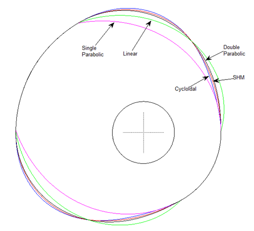
Figure 8 Overlaying of profiles for various cams used in plain weave design.
Conclusion
A comparison of different types of cam profile and their kinematics of the follower motion reveals that linear and parabolic cams generate infinity jerk at the start, whereas simple harmonic cam causes minimum jerk. A cycloidal cam ensures zero acceleration at the start as well as a perfect linking with the dwell and the changeover positions. The simple harmonic and cycloidal cams are suitable for high speed weaving.
Acknowledgments
None.
Conflict of interest
Authors declare that there is no conflict of interest.
References

©2019 Ghosh. This is an open access article distributed under the terms of the,
which
permits unrestricted use, distribution, and build upon your work non-commercially.


