eISSN: 2574-8092


Technical Paper Volume 9 Issue 1
1Department of Engineering, Saitama Institute of Technology, Japan
2Department of Engineering, Tokyo University of Science, Japan
3ITbook Technology, Japan
4Former ITbook holdings, Japan
Correspondence: Daishi Watabe, Engineering, Saitama Institute of Technology, Japan, Tel +81-48-585-2940
Received: December 29, 2022 | Published: January 9, 2023
Citation: Watabe D, Wada M, Shimizu N, et al. World’s first self-driving amphibious bus. Int Rob Auto J. 2023;9(1):1-6 DOI: 10.15406/iratj.2023.09.00254
Amphibious buses are extensively used worldwide for transporting people to and from tourist attractions across water and land. Although numerous studies on self-driving technologies have been reported, research on the automatic operation and navigation of an amphibious vehicle has been sparse; moreover, owing to the size of the amphibious vehicles, automatic transport of multiple people is not possible. Therefore, in this study, we attempted to realize unmanned operation of a sightseeing amphibious bus for 45 passengers. The bus was outfitted with a by-wire system. On the vessel side, an actuator, similar to that used in JOY cars, was installed to turn the captain’s steering wheel. We also developed a software for the automatic operation and navigation of the bus. The relationship between the car’s steering-wheel angle and the front-tire angles is linear, whereas that between the captain’s steering-wheel angle and the vessel’s rudder-plate angle is not (and was approximated with a sixth-order polynomial). Furthermore, Autoware—a leading autonomous-driving software utilizing model-based predictive control algorithms to control the steering wheel of automobiles—was employed in this work. These algorithms were altered using Nomoto’s KT vessel model equation to improve the accuracy of vessel-path tracking. To the best of our knowledge, till date, no studies have documented the functioning of self-driving vessels using predictive controls based on Nomoto’s KT vessel model equation. In accordance with the vessel navigation rules based on the Autoware obstacle avoidance logic, LiDAR, cameras, and sonars were employed to detect obstructions and give-way paths. Thus, we successfully demonstrated the working of world's first self-driving amphibious bus, with automated controls for entering/exiting water and during give-way operations.
Keywords: autonomous amphibious bus, self-driving amphibious bus, amphibious vehicle, self-driving bus
Amphibious buses are frequently employed worldwide as sightseeing vehicles to transport people across tourist spots over both land and water. In MEGURI2040’s Yamba Smart Mobility Project, we conducted trials to demonstrate the field operation of an autonomous amphibious bus. The automatic operation and navigation of amphibious vehicles have received less attention in existing studies compared to the self-driving technology in cars,1,2 and automatic navigation technology3,4 of vessels. Although amphibious robots5-7 are small, they have been studied scarcely, and even those studies have not focused on the automated conveyance of multiple passengers. Therefore, we worked on this novel premise to construct an autonomous, amphibious sightseeing bus with a capacity of 45 passengers. This paper reports the details of its construction, and the automation operations associated with the vehicle’s water entry, water exit, and obstacle avoidance.
Base amphibious bus
In this study, the authors attempted to perform the unmanned operation and navigation of an amphibious sightseeing bus named Yamadori-Tengu-Go (common name: Nyagaten-Go, Figure 1), with a capacity of 45 passengers. This bus also functions as a boat when in water, with a total length of 11.83 m and a gross weight of 11 tons.
The car is equipped with a hydraulic steering, an accelerator pedal, and a pneumatic brake pedal, while the boat is equipped with a hydraulic helm and a throttle lever (Figure 2).
Components of by-wire control (road and marine steering, pedal, and throttle lever)
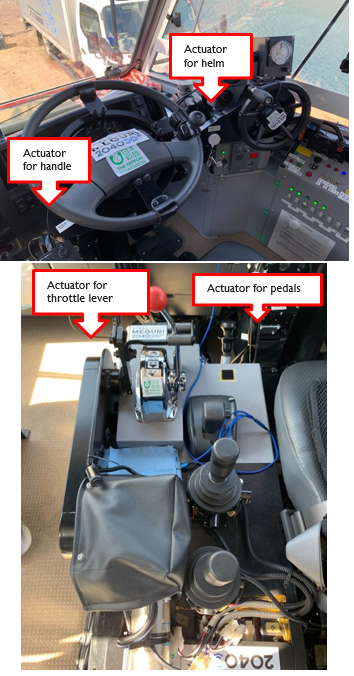
To realize unmanned operation of this amphibious bus, the steering wheel and pedals for the automobile function as well as the helm and throttle lever for the boat must be electronically controlled. We aimed to achieve the computerization required for this by incorporating the technology for our developed joystick cars, which are vehicles for people with severe disabilities, into the development of autonomous buses.8 We designed and fitted new actuators for the helm throttle lever, steering wheels, and pedals (Figure 3). The electromagnetic clutch, when shut, transmits actuator power to the helm, throttle lever, steering wheels, and pedals. Network signals for various functionalities, such as the opening and shutting of the clutch, starting and stopping the water-cooled marine engine (which uses water from the lake and can operate only in water), and elevation of screw propeller, were added to our developed vehicle-motion-controller, consisting of a control and relay board, to ensure controller-area network communication between the actuator and Autoware system (Figure 4). These functionalities allow the mended Autoware system to toggle between the vehicle’s land and marine transport modes upon entering and exiting water.

Figure 3 Actuator set on the steering wheel (top) and throttle lever (bottom). (Ship helm has more turn numbers compared to automobile handle).
Sensor (obstacle detection)
Because the interval for the scanlines of the range-finding laser of a rotary LiDAR sensor increases with distance, the laser, (horizontally installed,) does not hit (or detect) obstructions from a distance. For example, a LiDAR (Velodyne/VLS128), horizontally installed on the ceiling, can often fail to detect small boats (3m long x 5m above waterline) at a distance of 80 m, because they hide within the scanlines. Moreover, it is difficult for a vessel to safely stop or change course abruptly; therefore, a longer detection margin is necessary for marine navigation to allow sufficient time to control the ship. Therefore, we attempted to extend the detection range by installing rotary LiDARs (Velodyne/VLP32C) vertically under the left and right mirrors, in addition to the LiDAR (Velodyne/VLS128) on the ceiling installed horizontally. These three LiDARs (Figure 5) longitudinally and horizontally string the scanlines to detect obstacles (Figure 6). We found that with this installment, detection range of the small boat was extended to 120m.
Two cameras (Think Lucid/Triton TRI245S) were set up near the windshield. To get a field of vision spanning 94°, a lens with a focal distance of 25 mm (angle of view of 47°) was attached to the camera (Figure 7).
A sonar (TELEDYNE/M900) was set below the nose to detect underwater obstacles (Figure 8).
Sensor (location estimation)
The location was estimated using high-performance GNSS receivers (Novatel PowerPack7), optical fiber gyroscope sensors (ISA100) (Figures 9 and 10), and network RTK.
Basic configuration
The base software was Autoware.ai,9 which was customized by the Saitama Institute of Technology for automatic vehicle operation for experiments installed on ROS Melodic.8
Obstacle detection
We installed one sonar, four cameras (two at the front and two to the right and left), and a sensor-fusion function into the LiDAR. To detect obstacles with the sonar and cameras, a deep-learning method, YoloV3 of darknet, was used. The Euclidean cluster-analysis algorithm was used to identify the material body from the three-dimensional point group data of LiDAR. For an underwater obstruction, rectangular detection results were obtained from both the camera and LiDAR. When the percentage of overlap between a rectangle in a camera image and a point cloud of LiDAR data (after projection to the camera plane) exceeds the threshold (assumed to be 20% in the pilot study), it is considered that an obstruction has been detected. The relationship between the 3D location and planned route was used to determine if the obstruction needed to be avoided. Conversely, for an underwater obstruction, the relationship between the rectangular location in a sonar image (given in the 2D image shown in Figure 17) and a planned route was obtained.
Route tracking
Model predictive control (MPC) in Autoware was used for route tracking. To determine automobile steering angles, MPC solves a convex optimization problem with a kinematic rear-wheel axis model which inputs a reference route as feedforward and the most recent wheel angle as feedback. In order to extend this method to the amphibious bus, we prepared MPC for vessels by substituting the model equation for automobiles (a kinematic rear-wheel axis model) to that for vessels (Nomoto’s KT equation). In the case where the amphibious bus is attempting to enter/exit the water, both models are used simultaneously. To the best of our knowledge, there is no research documenting the operations of a self-driving vessel modeled with predictive control employing the kinematic model equation and Nomoto’s KT equation simultaneously for a single vehicle (Figure 11). The relationship between the steering wheel angle of the car and front tire angles is linear, whereas that between the helm and rudder-plate angles is not, and was approximated with a sixth-order polynomial.
Entering water
The aforementioned models were switched when the vessel entered the water. After this point, the screw propeller was lowered, vessel engine was turned on, and the shift lever on the bus side was set to neutral. Owing to oscillations created when the vehicle entered the water, position estimates were unstable throughout route tracking. Therefore, we selected the marine profile of the GNSS receiver made by NovaTel to stabilize the location estimates.
Exiting water
The above models were again switched when the vessel exited the water. At this point, the vessel engine was turned off, screw was moved up, and shift lever on the bus side was set at M2 (manual second). If the vessel’s route-tracking is inaccurate during its exit from the water, it can cause the vehicle to run off the landing slope, which would be dangerous. Therefore, high precision is needed for the route tracking of the vessel while exiting from the water.
Obstacle avoidance
For obstacle avoidance, Autoware’s A* algorithm was employed. To obey the vessel maritime obstacle avoidance action of turning right, we created the cost-map for A* algorithm with the high cost left side (even though there is no obstacle in the left) in order not to turn left. We tuned the algorithm to generate routes that the vessel might follow. The generated avoidance routes were sent to the route-tracking function delivered as a topic of new local waypoints and utilized it to compute the steering angles in the function.
From the perspective of cost computation, the size of the cost map used to generate avoidance routes was set to 150 m x 150 m.
Route tracking
We conducted an experiment on vessel route-tracking in Yamba Dam Lake for the route shown in Figure 12. This route was made by manual navigation. The vertical and horizontal axes indicate the coordinate values of the 9th system of the planar rectangular coordinate system.
Figure 13 depicts the tracking error from the planned route shown in Figure 12 using two different set-ups: MPC and pure pursuit. Further, Nomoto’s equation was used to describe circular arcs in pure pursuit, and compared under the same conditions as MPC (K:T = 1:4). This proved that shear from the planned route considerably improved when MPC was used. The standard deviation of pure pursuit was 1.594 while that using MPC was 0.405.
Entering water
Figure 14 shows the state of the vessel during water entry. Although the location estimates were unstable when the vessel oscillated, it was overcome using a marine setting for the GNSS receiver.

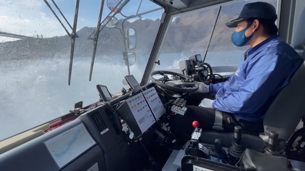
Figure 14 State of entering water. It can be observed that the test driver moves his hands away from the handle, helm, and throttle lever. Moreover, his foot is off the pedal even though it is not visible in the figure.
Leaving water
Figure 15 shows the state of the vehicle on exiting water and re-entering land. The steering accuracy was considerably improved by MPC, which allowed a more precise landing for the vehicle.

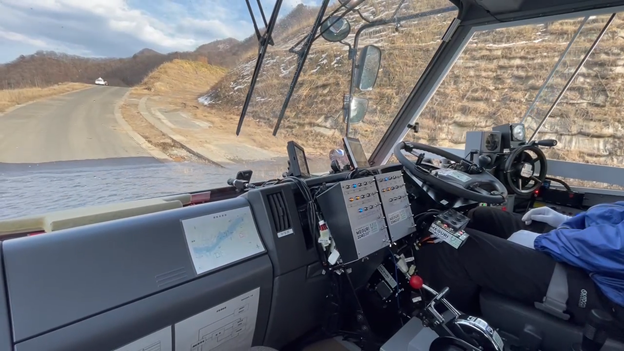
Figure 15 State of leaving water. It can be observed that that the test driver moves his hands away from the handle, helm, throttle lever. Moreover, his foot is off the pedal even though it is not visible in the figure.
Obstacle detection
Figure 16 shows the results of obstacle detection obtained via LiDAR and the cameras. The smaller red square indicates a point-group image of the boat detected by LiDAR, while the larger one is its magnification. It is noteworthy that even sizes as small as 10 pixels and 20 pixels were recognized as a boat. Figure 17 depicts the results of the obstacle-detection experiment using sonar. A fisherman’s net was detected from approximately 40 m away.
Obstacle avoidance
Figures 18 and 19 display the states of obstacle avoidance.
An avoidance route was generated with the distance between the amphibious bus and boat in the range of 70–90 m (Figure 18). The parameters for curvature-enabled tracking of the generated route were then optimized (Figure 19).
The automated entry and exit of a 45-passenger amphibious bus into and from water, along with obstacle avoidance, were the initial goals of this study. These initial goals were successfully achieved. A small island that suffers from rapid aging and decreasing population can benefit from the developed self-driving amphibious bus, as it does not need drivers, captains, or workers on the beach to load and unload carriers. This project has not only been published10 and aired over television,11 but has also been introduced in influential overseas societies12-13 and published in illustrated vehicle books for children,14 all of which have a huge impact on society. Even though our technological development is still in its early stages, we want to make it as comprehensive as possible as a means of meeting societal demands.
The consortium of IT book Holdings, Japan Amphibious Vehicle Organization, Naganohara Town, ABIT, and Saitama Institute of Technology, carried out the development and experimentation for this project with funding from the Nippon Foundation. The authors sincerely thank the consortium members, the Nippon Foundation, as well as the businesses and organizations involved in this study. This paper is an English translation of the authors’ technical review paper in Japanese published in Navigation vol. 221 (the periodical of Japan Institute of Navigation).15 The reprint permission is obtained from the Japan Institute of Navigation (official document no.2022-78) with the condition that further reprint is prohibited.
The Authors declare that there is no conflict of interest.

©2023 Watabe, et al. This is an open access article distributed under the terms of the, which permits unrestricted use, distribution, and build upon your work non-commercially.