eISSN: 2574-8092


Review Article Volume 4 Issue 6
The Polytechnic School, Arizona State University, USA
Correspondence: Sangram Redkar, the Polytechnic School, Arizona State University, Mesa, AZ – 85212, USA
Received: October 19, 2018 | Published: November 27, 2018
Citation: Bhat SG, Redkar S. Volitional control of an active prosthetic ankle: a survey. Int Rob Auto J. 2018;4(6):380-388. DOI: 10.15406/iratj.2018.04.00153
In this work, state of the art in the field of intent recognition, its application to prostheses and subsequent volitional control algorithms are reviewed. In this paper, competitive landscape is also studied with the aim to learn from the successes and failures of the researchers who have been working in this area. This research hopes to further advance the technology for volitional control of prostheses/wearable robots that will enable much integrated human robot collaboration/interaction specifically focused on passive and active prostheses. The overarching aim of this work is to develop a prosthetic ankle that is as close to a human ankle as possible.
Keywords: ankle, survey, vascular diseases, adapting, mechanism, efficient and stable
There are 185,000 new leg amputations each year in the USA alone.1 The major reasons for leg amputations are vascular diseases (54%), trauma (45%), and cancer (less than 1%), to mention a few.2 There is a dire need for prosthetic devices that operate as effectively as human limbs. The recent advancements in prosthetic and biomedical technologies along with novel control algorithms present an opportunity to dig deeper into the idea of a truly bionic prosthesis. The article discusses novel ideologies put forth by the researchers in their attempt to create perfect prosthetic limb. This article is organized as follows: initially a detailed survey of passive prostheses is presented followed by a discussion on active prosthesis. Later a review of intent recognition is included along with its application to volitional control systems. Finally, a conclusion is drawn based on overall literature review.
Passive lower limb prostheses
A passive prosthesis is defined as a device that doesn’t require external power to operate and generally doesn’t contain control electronics. Typically, these devices cannot be controlled as per user’s intent. However, it is important to review these classes of devices as many active prosthetic devices have many elements that are common to their passive counterparts. Quite a few researchers have published their findings in scientific journals as discussed below.
Volition control of prostheses is more important during activities like walking uphill, downhill, climbing stairs, side-stepping, etc. There are a few passive devices that allow limited volitional control as discussed by Hansen and his team Hansen et al.3 studied the characteristics of human gait on inclines. They studied the roll-over shapes of able bodied human beings over level ground, 5-degree ramp and 10-degree ramp. Two types of roll over shapes were studied: Ankle-Foot roll-over shape (AF) and Knee-Ankle-Foot roll over shape (KAF). After performing their tests and experiments, they found that AF roll-over shapes worked well for uphill walking but KAF rollover shapes were better with both type of inclinations. They concluded that proper ankle actuation improves uphill walking and efficient knee actuation is beneficial for downhill walking.
Vrieling et al.3 did something similar and studied how amputee’s gait adapts to inclines. The study included a variety of test subjects (seven trans-femoral amputees, twelve trans-tibial amputees and ten able-bodied people). This was different than what Hansen et al. did as amputee gait was studied along with able bodied gait. The data agreed with Hansen et al.’s result that knee flexion is important during uphill or downhill walking.4 Similarly, Williams et al. developed a prosthetic ankle capable of adapting to the walking surface. Their design used a locking cam mechanism, which locked depending on gait transitions. It had three compliant components that defined the overall dynamics of the ankle. The ankle prototypes were tested on three test subjects and compared with their own daily use prosthetic devices. The test results shown in Figure 1 explain how their design is better than the subject’s usual prosthesis in adapting to the slopes and providing better flexion of the ankle.5
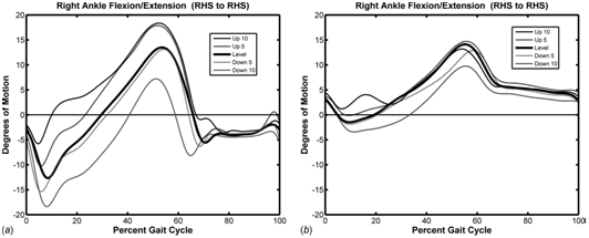
Figure 1 Ankle flexion/extension curve for Developed prosthesis. (B) Subject’s usual prosthesis in William et al.5
Later in 2012, Brackx et al.5 designed a prosthetic ankle with extended push off capability.6 They observed that the prostheses during that period mostly consisted of springs, which couldn’t provide a good push off. So, they came up with a novel idea with planetary gears, locking mechanism and springs. Figure 2 shows the CAD model of their planetary gear mechanism. They experimented on a transfemoral amputee and collected data. Their experiments showed that their design worked and there was energy release during the entirety of the push-off phase of the gait cycle.
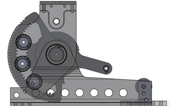
Figure 2 Planetary gear mechanisms in Brackx et al.6
In the same vein as Brackx et al.5 Mooney and his team found that the existing prosthetic ankles at their time were incapable of providing the amputee with “biologically realistic” ankle torque and angles.7 They developed a quasi-passive ankle with pneumatic components. They compared their ankle with a passive ESR prosthetic foot. Their results suggested more parameter tuning is required in their design. Recently, Nickel et al.8 developed a passive prosthetic ankle that automatically adapted to the ground’s inclination. All this was achieved using a cam mechanism that changed the equilibrium point which allowed the flexible foot to store energy during plantar flexion. They tested their ankle prototype on inclines ranging from -10 to 10degrees. The test subjects experienced ease during downhill decent but uphill ascent was difficult. All the test data was compared to the prosthesis that the test subjects used daily. Nickel et al.7 outlined user experience while wearing the prosthesis. The experimental data is shown in Figure 3 that compares kinematic and kinetic data from their prototype and the subject’s prosthesis. Their experiments showed that the subjects felt less fatigued when using the prototype.
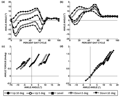
Figure 3 Kinematic and kinetic data comparison between prototype (A) & (C) and user’s prosthetic ankle (B) & (D).8
Very recently, Amiot et al.9 developed a passive hydraulic design (Figure 4) for a prosthetic ankle as a proof of concept. Their design allowed the ankle to change foot angles according to the slopes. This design had a flexible foot and spring to store energy during plantar flexion. The hydraulic circuit equalized pressure when the foot was flat on the ground. The hydraulic losses in the system were compensated by the energy stored in the flexible foot keeping the system efficient and stable.
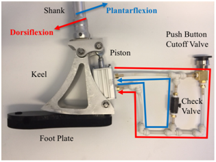
Figure 4 Hydraulic system used in Amiot et al.9
In the same year, Nguyen et al. designed and developed a revised iteration of their prosthetic ankle that was compliant in 6degrees of freedom.10 It was a sheet of metal bent to the shape of an ankle as shown in Figure 5. They analyzed the design to check for stress characteristics and found that the design had a better strain energy storage when compared to the previous iterations. They did not test the ankle in real life experiments where the ankle behavior could be different. Figure 6 shows their ankle and its degrees of freedom. Many interesting mechanisms for passive prostheses were studied above. In summary, it is safe to say that none of them individually provide everything expected off a human ankle. This article will discuss active prostheses and their advantages over passive prostheses in the next section.
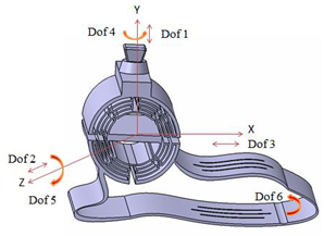
Figure 5 Possible degrees of freedom in Nguyen et al.10
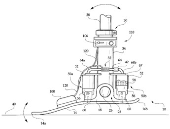
Figure 6 Koniuk's self-adjusting prosthetic ankle apparatus.11
Actively controlled lower limb prostheses
Active prostheses, unlike passive prostheses, are controllable. The control strategy and active components used in the prosthesis determine the device’s effectiveness. The state of the art and history of research on active prostheses is discussed below. In 2001, Wayne Koniuk filed for a patent on his idea of a “Self-adjusting prosthetic ankle apparatus”.11 It included two computer controlled dampers that varied their stiffness based on the relative motion between the footplate and the ankle. The patent document outlined the general architecture of the control loop that resulted in proper gait. Figure 6 shows the schematic diagram of the ankle. Along similar lines, Englehart et al.11 developed a myoelectric control algorithm to control an upper body limb prosthesis.12 Multiple classes of the myoelectric signal were discriminated into classes of different limb movements. There was no need for segmentation of the data and hence the algorithm worked in real time. They were successful in acquiring good accuracy and response time. This system was fast as it utilized minimal storage space on the controller.
Similarly, Au et al.12 conducted a research on EMG (electro-myogram) based controller for an active foot prosthesis. The EMG measured the signals in the amputee’s residual leg to control the ankle. Their research article compared EMG based controllers with the neural network approach. They observed that the EMG based control was smoother and more reliable.13 Later in 2006, Parker et al.13 studied the use of myoelectric signals for control of powered prostheses.14 They looked at various aspects of myoelectric signals and their control applications viz. challenges, state of the art, types of signal processing algorithms, etc. among other things. They later discussed the future of myoelectric signal based control. They believed the field of myoelectric sensors had potential in active prostheses control.
On the other hand, Samuel Au and his team did not use myoelectric signals and studied the biomechanics and design of an active prosthetic ankle in 2007.15 It used a Series Elastic Actuator (SEA) for actuation of the ankle along with a passive unidirectional spring in parallel. The foot used was the flex foot LP Vari-Flex. The major goal of this design experiment was to develop a prosthetic ankle that would conform to the size and shape requirements of a human ankle without compromising the gait. In the same year, Fite et al.15 designed and developed a prosthesis with a powered knee.16 They applied an impedance based control on the active knee. The prosthesis was designed for walking on level ground. They concluded that this configuration would be good for slope or stair walking given a better control algorithm and characterization of the energy required (Figure 7).
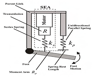
Figure 7 Schematic diagram of Au et al.18
In similar fashion, Sup et al. designed a powered knee and ankle prosthesis.17A spring in parallel with the motor at the ankle joint decreased power consumption during push off. They used a finite-state based impedance control approach. The experiments they performed showed the potential of the prosthesis to perform normal gait. They also concentrated on energy consumption of the prosthesis. Their design worked for a walking distance of 5km with a lithium polymer battery pack. Parallel to Sup and his team’s research, Bellman et al. developed a prosthetic ankle that would provide the wearer agility and athletic capabilities.18 They named the ankle SPARKy (Spring Ankle with Regenerative Kinetics). This was the 3rd iteration of the ankle. The U.S. Army Medical Research & Material Command funded the research for military amputees to provide them a chance to return to active duty. They used two springs in parallel on the foot plate to store and release energy (Figure 8). Two motors were used to add additional energy to the springs as a regenerative method. This iteration was a two degree of freedom ankle as opposed to their earlier versions which had a single degree of freedom. Meanwhile, Au et al. improved their existing design from 2007 and developed it to assist stair descent.19 They controlled their ankle using myoelectric signals employing a finite state controller. Their goal was to control both impedance and power output while in stance phase. They investigated the muscle groups that activate when the subject switches from level ground walking to stair-descent and used those muscle signals to switch the prosthetic controller from one finite state to other. Later in 2009, they tackled the issue of low net work provided by their prosthetic ankle. Au et al. researched and proved that an active prosthetic ankle that mimicked human ankle in terms of work and torque would reduce the metabolic cost of walking.20 They observed that the metabolic cost of walking reduced by about 14% when compared to the passive elastic prosthetic ankles available to them.
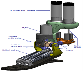
Figure 8 Sparky 3.17
On the contrary, Holgate et al. studied various control algorithms present in 2009 and developed a novel algorithm that considered the orientation and angular velocity of the tibia as the input to determine the gait events.21 Their simulation showed that this approach could be useful and gave angles close to that of a healthy human ankle. Figure 9 shows the output of their algorithm. The articles studied above describe the various active prostheses that were developed. These devices worked without any user intention information. Introducing intent recognition into an active prosthetic system will make the system truly automated in its operation. In the next section, intent recognition systems are studied to understand their operation.
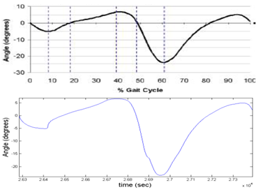
Figure 9 Ankle angle curve of a healthy human (top) ankle angle curve from the tibia based controller.21
Intent recognition
Intent recognition/volitional control is a form of machine learning which specifically applies to humans and human related tasks. It has been applied to predict human gait and other tasks performed by human beings. To discuss its application, Hargrove et al. studied the use of myoelectric signals, which are well known to have a lot of disturbances.22 They found that by transforming the signals using class specific principal components, the measured data can be spatially de-correlated and used as an input to a pattern recognition classifier. They developed individual Principle Components Analysis (iPCA) which resulted into a much lower pattern recognition error in amputees as well as able bodied human beings. Later in 2010, Varol and his team studied control algorithms and intent recognition approaches for active prosthetic ankles.23 They developed a novel idea that worked in real time and recognized user intent to sit, stand, and walk. They used the signalsfrom the residual leg as the input. Figure 10 shows the state diagram used by the algorithm. Varol et al. trained the algorithm and applied their findings on a prosthetic ankle. They used PCA and Linear Discriminant Analysis (LDA) methods for reducing the dimension of the raw signal and Gaussian Mixture Model (GMM) as a classifier.
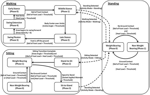
Figure 10 State charts with separate standing, walking, and sitting phases.23
On the contrary, Scheme et al. researched the field of EMG based pattern recognition and discussed the issues and practices that existed in 2011.24 The article described the most important aspects of pattern-recognition based control and discussed future changes and innovations in this field. Similarly, Zhang et al. again used EMG in real time to recognize the user’s intent for locomotion, sitting and standing.25 The system was tested on a prosthetic leg worn by a transfemoral amputee. Figure 11 shows the gait phase detection criteria used by the classifier. Zhang and his team found that in static cases (same task performed repeatedly) the recognizer worked well. Hence concluding that neural control of prosthetic leg was a potential solution to intent recognition. From a slightly different perspective, Zhang et al. presented an idea in the hardware side of intent recognition.26 They used Field Programmable Gate Arrays (FPGA) in unison with a microprocessor unit as their hardware. This allowed them to achieve fast decoding and recognition of EMG signals for a better and more stable control of the prosthesis.
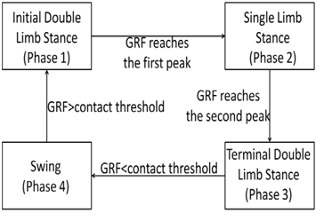
Figure 11 Phase detection criteria.25
Recently, Young et al. tackled the problem of transition between phases in intent recognition systems.27 They used Dynamic Bayesian Network (DBN) as a classifier for neural and mechanical signals. This method was useful for stairs but didn’t provide good enough recognition in case of ramps. They claimed to have achieved a transitional error of 11.3%. They also observed that if the classifier was trained for ramp walking as level ground walking; the error rate was massively reduced. In 2014, they tried a different approach to the same problem by using the time history approach.28 Figure 12 shows the number of windows selected for each approach. It was seen that by using time history the transitions were smoother and misclassifications were largely reduced.
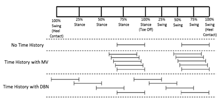
Figure 12 Each classification strategy’s time windows. Two windows for ‘No Time History’, five windows for ‘Time History with MV’ at an event, and well distributed eight windows for ‘Time History with DBN’ strategy.28
All these articles indicate that intent recognition could solve many problems and provide efficiency when applied to prostheses in the correct form. In the next section, application of intent recognition to prosthetic devices is studied.
Volitional control of prostheses
Volitional control can prove to be a very important tool in achieving the goal of a truly bionic prosthesis. This type of control may or may not utilize intent recognition algorithms. A few articles by the researchers in this field are discussed below.
To achieve subconscious control for above knee prostheses, Myers et al.29 developed an algorithm. They used EMG sensors and separated these signals for different activities viz. knee flexion, knee extension, and hip action on an above knee amputee. Figure 13 explains the procedure used to separate the signals. They observed that the error in classifying largely depended on the training procedure used. Following suit, Hansen et al. presented a method for detection of gait events.30 They used the center of pressure data along with an ankle marker to detect gait events which was a novel idea. They were successful in detecting heel-strike and toe-off events in their experiments. Hansen and team’s experiments compared their approach to that of an individual force plate approach and found that their approach was better and faster.
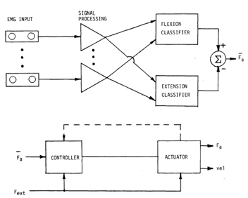
Figure 13 Schematic diagrams for the control algorithm.29
Years later, Ha and his team developed a method for providing control over one’s prosthetic ankle in non-weight-bearing situations.31 Again, EMG sensors were used to volitionally control the impedance of the prosthetic knee joint. Figure 14 show how the choice of classifier (QDA or LDA) yielded different results. They found little to no error in the large amplitude EMG classification using QDA method. Similar to Ha et al., Zhang and his team conducted a study on the effects of error in recognizing the locomotion mode.32 They hypothesized that these errors would affect the gait stability of the user. After their experiments, they concluded that there are only some “critical errors” that affect mode recognition and should be taken into consideration when using intent recognition for volition control. These “critical errors” depend on the classifier and method of implementation. Among all the articles studied, there were some that didn’t fit into any category mentioned above. They were still essential to make some concepts clear. These articles are discussed in the next section.
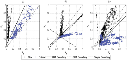
Figure 14 Classification of reference signals using LDA and QDA.31
Supplemental research material
In 1979, Hartigan and Wong wrote an article on applied statistical method of K-means clustering.33 Method of K-means clustering is used in machine learning to obtain a cluster of points which then can be used to recognize individual intent or data points. It divides M points in N dimensions into K clusters so that the sum of squares is minimized. This makes it possible for the classifier to identify each activity. On a different note, a study on human psychology conducted by Haggard et al.34 aimed at finding the local time a human being perceives the occurrence of motion. They found that a person is aware of his/her motion sometime between the thought of movement and the time his/her muscles gets the motor signal. Every algorithm for intent recognition desired to do the same thing. This study showed that there was a certain lag in the perception of human movement. Hence, it proved that the technology is not far from developing a method of control that is close to the human physical system.
Moving into the field of medicine and surgery, Zhou and his team discovered a new method of amplifying the muscle signals in their research article.35 They called it Targeted Muscle Reinnervation (TMR). TMR was a process where the residual nerves from an amputee’s limb was transferred into the nonfunctional muscles. This amplified the motor commands in the nerves, which were then picked up by the EMG sensors. They applied this method on a prosthetic arm and were successful in improving accuracy of the classifier in 16 movements. In contrast, Hargrove and team outlined their experiment on myoelectric control of motion in a prosthetic leg in reference.36 Their work showed that similar control as achieved by Zhou et al.35 can be achieved without muscle reinnervation for non-weight bearing activities. But their experiment was conducted in a virtually simulated environment. No attempt at replicating the results on a real prosthesis was made.
Later in 2014, Rajtukova et al. studied the biomechanics of a lower limb prosthesis.37 Their article talked about the way prostheses should be designed and constructed with consideration to socket comfort and posture of the amputee after donning the prosthesis. It outlined the adverse effects of not conforming to the biomechanics on gait of the amputee. Figure 15 depicts one of the bad effects discussed in the paper. After reviewing all the above articles, the methods and practices used by the researchers were scrutinized. 38
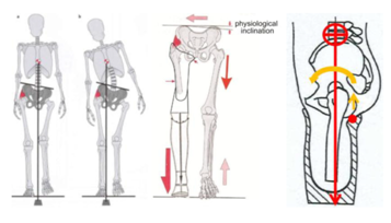
Figure 15 Torsion in the hips due to a bad design of a prosthetic leg.37
Some of the researchers used simple and well defined experimental setups,3,5 while some used a good sample of subjects for reliable experimental results.4 Whatever the emphasis may have been, each research had their own strengths and flaws. Hansen et al.’s explanation on Ankle-Foot and Knee-Ankle-Foot systems was thorough and their results explained the way these two systems were better at separate tasks. But their experiment did not take the Center of Pressure (COP) data into consideration while also estimating the hip position.3 For better reliability; they should have modified their setup to incorporate some substitute to the COP information of the Ground Reaction Force (GRF) e.g. global co-ordinates of the force in unison to the location of the ankle or something similar. On the other hand, using a marker for the hip location would have helped.
Following a different school of thought, Vrieling and his team’s research emphasized more on discretized data at different instances of the gait while neglecting the continuous gait cycle data.4 Also, the results discussed only the mean value and the individual test results were not mentioned. Hence the outlier data were not available. Sharing the outlier data would have fortified the results and a better conclusion could have been drawn. But nevertheless, the described data compared the amputee gait with the able-bodied gait thoroughly. Using research done before them, Williams et al. developed a locking mechanism to vary foot angle as per the ground inclination.5 This was a novel design at the time. The prototype was tested on varying slopes leading to proper analysis of the usability of the ankle. This design was just a proof of concept and the results were not discussed in detail. Furthermore, comparison was drawn between the subject’s prosthesis and the prototype and no comparison to normal gait was made. A thorough comparison between prototype and a human ankle would have given perspective to the results as the subject’s prosthesis was not mentioned.
With a different goal, Brackx et al. created a mechanism to improve the push-off of passive ankles.6 Their mechanism, though successful in providing good push-off, was very bulky and was near impossible for daily use. Their article does not discuss the experimental procedure in detail. They mention using data from a single stride which may mean proper design of experiment was absent. They could have included data from multiple subjects with multiple load conditions to properly assess the ankle’s capabilities. Unlike the articles before where the ankles were passive, Mooney et al. developed a quasi-passive prosthetic ankle using a pneumatic piston-cylinder assembly.7 This assembly seemed bulky and not useful for daily use. The fluctuation in internal pressure of the cylinder would cause a difference in the ankle’s output. Their article does not discuss the behavior of the ankle during swing phase. But they thoroughly discuss the COP data and compare it with that of the human ankle. Their design needs improve while also refining the behavior of the pneumatic system. The experiments conducted could have used more planning in data collection.
Coming back to slope adaptable ankle mechanisms, Nickel et al. developed a cam based design.8 Their design used a flexible foot to provide push-off. Like,5 they tested their ankle on varying slopes. They used custom MATLAB scripts to improve accuracy of the data processed. They discussed user experience in the article, which was missing from the research done before them. While Nickel and his team’s work had a lot of pros, there were some shortcomings as well. They had no comparison data for their prototype with normal gait of a human ankle. The sample size used in their experiment left one wanting more. Their design, though innovative, was complicated and would prove difficult to maintain.
Similar to,8 Amiot et al.9 used a flexible foot to make their version of the ankle slope adaptable. Their use of hydraulic components in the system is just like.7 The hydraulic system makes the ankle difficult to maintain. They explained their use of the hydraulic system well in their article. But they focused heavily on the gait of the ankle on level ground while incline walking tests were scarce. Their ankle was just a proof of concept and no further attempts were made to improve the design. On the other hand, Nguyen and his team made some improvements to their previous design.10 Their article heavily focused on design and analysis. There was no experimentation or simulation for gait using their design. Strain on the ankle for different phases of the gait were analyzed and discussed. Their article is new and there is still hope that they will soon conduct some experiments and publish their results. A good approach would be to test their ankle prototype on level ground for simple gait, before trying something ambitious. Also, they did not consider the user wearing a shoe over the prosthesis which can alter the real-life results considerably. With the articles on passive ankles scrutinized, the next section focuses on active ankles and other active prosthesis.
Englehart and Hudgins investigated the control of upper limb prosthesis using myoelectric signals.12 For controlling the prosthesis, they used four channels of data. Their experimental sample size was good with 12 able bodied subjects. The data collected from these subjects was converted into a feature set which meant loss in data. They did not use a separate training procedure for the classifiers but instead used half of the collected data for training purposes. Also, the window length used had nothing to support the selection. The data obtained was well explained and discussed in depth. Unlike Englehart and team, Au et al.’s approach to EMG based ankle prosthesis control was more qualitatively.13 The ankle prosthesis was simulated and the EMG signals from the residual leg of the test subject were used to control the simulated ankle joint. The introduction of actual ankle foot prosthesis might add unknown terms into the dynamics and may change the output of the algorithm. They compared neural network approach with biomimetic approach. They found that qualitatively, both approaches were equivalent which is logical.
Different form their previous research, Au et al. focused on the biomechanics of gait for developing a powered prosthesis.15 They discussed the engineering challenges present in building a bionic ankle which shows they researched the topic well. Their design was simple and easily controllable. Their selection of the springs seemed arbitrary and they should have explained their reasons more. They simulated the setup as opposed to creating a prototype which would have given more accurate results. In another article, they discussed the usefulness of their design for assisting level-ground walking and stair-descent.19 They explain the various stages of the control flow for both level ground and stair-descent well. Again, all this was simulated using similar setup as in.15 Their experimental setup looked bulky and impractical for a simulation. The simulation results were well explained. They continued their research again.20 This time they focused the metabolic cost of using a prosthesis. This article mentioned gait experiments and discussed the results. The results show that the prosthesis decreases metabolic cost. The gait data shown are close to a human ankle’s data.
While Au and team’s research was design based, Fite focused on control strategy. Fite et al. used an impedance-based control approach to control their knee prosthetic.16 They used an able-bodied testing adapter with their prototype for their experiments. The operation of the prototype was related to the heel strike and toe-off events, which meant the other events were estimated based on those two events. This would have introduced some error in the operation of the prosthesis. Their design was good and with a proper control algorithm it could give a near perfect gait. With similar intentions, Sup et al. set out to develop an active knee and ankle prosthesis.17 Their prosthesis was tested on an adapter worn by an able-bodied subject simulating an amputee. This adapter can introduce some unwanted errors.16 They used an impedance based control algorithm to control the prosthesis. The results are well depicted but some more discussion would have been better.
Coming back to design, Bellman et al. used regenerative kinetics for the operation of their prosthetic ankle.18 Their SPARKy 3 ankle was an improvement over their previous iterations. The article discussed various design details and their reasons behind selecting certain components, but, there is no simulation or experimental data available to weigh their designs’ usefulness. To create a better control algorithm, Holgate et al. used the phase plane variables to detect gait events and control their wearable robot.21 Their controller used tibia based variables as the input. Tibia angle and angular velocity was used on the phase plane to acquire the polar co-ordinates of any given instance. The algorithm then processed these co-ordinates to obtain the control signals. They performed detailed simulations but did not apply the system on an actual prosthesis. As shown in Figure 9, the results of the simulation were close to the actual ankle angles. Moving on from control strategy to human input and intention, next section discusses articles on intent recognition.
Hargrove et al. ventured into the field of pattern-recognition based myoelectric control.22 They placed 10sensors around the forearm equidistant from each other. Their experimental procedure was well designed. They analyzed the results using two-way ANOVA to obtain the error percentage. They discussed variation in intrasubject error and drew conclusions from these data. Their conclusion that iPCA processing reduces classification error is well founded on dependable proofs and results.
While Hargrove and team’s article focused on classification errors, Varol et al. concentrated on the application of the PCA and LDA methods in real time intent recognition.23 Their use of GMMs was useful. They also used PCA to process the data. The data used for processing was a reduced version of the original data. This was done to improve processing time while implementing in real time, but they also lost considerable data due to the reduction. The use of PCA was hence justified. The experiment was conducted on only one subject. Combining multiple subject data would have fortified the results. Nonetheless, their results are well represented and discussed in detail. Along similar lines, Scheme and Englehart discussed the challenges of EMG pattern recognition in clinical use.24 The article was a review article and commented on various practices and their effects. They discussed various factors contributing to classification accuracy in intent recognition. They explored many classification techniques to establish a comparison between their error generations. They also studied the effect of force levels between training and test data sets.
Following suit, Zhang et al.’s implementation of intent recognition on prosthetics involved a different approach.25 Instead of the traditional way of linearizing the nonlinear equations; they used a nonlinear classifier to classify the data accurately. This reduced the errors introduced into the analysis due to linearization. The nonlinear classifier used is known as Support Vector Machine (SVM). SVM is known to be computationally efficient. Sample size was only one subject. They obtained mode transition accuracy of 98.36% which is good. But they used a bi-mode approach and did not study the effects of the mode changing thrice.
Similarly, Young et al.’s new strategy for recognition and activation of different locomotion mode was not perfect.27 Their sample size for experimentation was good. They investigated the behavior of their selection of classifiers. They also used a time-history based classification method to improve their analysis. But, they had no alibi for their selection of the number or duration of the time window used. Their classifier training could have been improved by training for multiple mode transitions. Their article, overall, was well put and their experiments were well designed. They divulged further about time-history information and its effects on intent recognition.28 Their comparison of various types of time windows used in classifiers was good and showed that it had some effect on the classifier output. The various time windows used can be seen in Figure 12. Their results clearly show that time history with DBN reduces the error considerably for steady-state classifications while it has no effect during the transitional phase. The above articles were focused on intent recognition in a broad manner. The next section focuses on recognizing the intent for particular operations.
Myers et al.’s research on myoelectric pattern recognition concentrated on the math side of the technology.29 Their focus was on classifier selection. They compared the performance various classifiers viz. Polynomial Discriminate Function (PDF), Quadratic Discriminate Function (QDF) and Linear Discriminate Function (LDF). Each of these classifiers were trained intensively for their experiments. The article explains the flow of data in detail, but overlooks the application of the process. Myers and his team made no attempts to test the classifiers during gait. Collection of the gait data might have opened new avenues for testing. Similarly, Hansen and his team’s approach to determining gait events had some flaws.30 They used the COP of the GRF along with a marker at the ankle as their input. Addition of another knee or shank marker would have improved the results. Also, they only detected heel strike and toe-off events and estimated the other events. This might have introduced some estimation errors. Accurate event data for the experiment would have been obtained using some redundant sensors. The data obtained from their experiments were not compared to normal actual gait. So, there was no evidence that the estimated events were accurate. These shortcomings aside, the article introduced a novel concept.
Though not a new development, Ha et al. researched the control of a prosthetic knee using electromyography.31 They did not experiment weight bearing motion and only concentrated on movement of the leg while seated. Their protocol allowed co contraction data (contraction of multiple muscle groups when only one muscle group contraction is desired). This led to a real world like data collection. They compared QDF and LDF and settled on using QDF analysis method. To filter and process the data, they used the Principal Component Analysis (PCA) method. Their experiments yielded a standard deviation of 0.71. The experiments could have been improved by using a more accurate alternative to EMG. Also, their sensors were not integrated into the prosthesis. The results might vary post integration. While many researchers prior to them used EMGs, Zhang et al. set out to measure the errors in mode recognition due to movement.32 Their experimental setup involved a knee ankle prosthesis. They collected data from 5 able bodied subjects and 2 above knee amputees. The sample size used could have been improved by involving more subject data. Still, the acquired data is processed well and the data representation in the article is commendable. They discuss the error duration in various mode recognition though their depiction of mode instability could have been better. All the above-mentioned positives and negatives from the research articles must be noted as they would be useful for future research. The comments made on all the articles above will be used to form a clear and concise research plan for the topic selected.
This paper provides a brief review of the technological advancement in the field of passive prostheses, active prostheses, intent recognition, and volitional control. All attempts until now to create a bionic prosthesis have been partially successful. Passive prostheses have proven to be inefficient but are cheap and require no external power. Active prostheses, though expensive and power hungry, display higher efficiency. The potential of intent recognition strategies with application on prostheses was recognized. A well thought amalgam of all the technologies studied above will result in a better prosthesis. After studying all the above discussed articles, it can be asserted that the dream of achieving a truly bionic prosthesis is close to becoming reality.
None.
The author declares there are no conflicts of interest.

©2018 Bhat, et al. This is an open access article distributed under the terms of the, which permits unrestricted use, distribution, and build upon your work non-commercially.