
Research Article Volume 2 Issue 4
Stability analysis of a multilink flexible manipulator: nonlinear observers
Qimin Xu,
Regret for the inconvenience: we are taking measures to prevent fraudulent form submissions by extractors and page crawlers. Please type the correct Captcha word to see email ID.

Zhonglian Jing, Shiqiang Hu
School of Aeronautics and Astronautics, Shanghai Jiao Tong University, China
Correspondence: Qimin Xu, School of Aeronautics and Astronautics, Shanghai Jiao Tong University, China
Received: March 17, 2017 | Published: June 2, 2017
Citation: Xu Q, Jing Z, Hu S. Stability analysis of a multilink flexible manipulator: nonlinear observers. Int Rob Auto J. 2017;2(4):107-117. DOI: 10.15406/iratj.2017.02.00024
Download PDF
Abstract
This paper is concerned with stability analysis problem of nonlinear observer design for a class of multilink flexible manipulators (MLFMs). Specifically, the dynamics of the MLFM is modeled by the use of a Lagrangian approach. In a unified algebraic Riccati matrix equality (ARME) framework, one corresponding error-state system is proven to be asymptotic stable in the mean square (ASMS) for a nonlinear observer design with a known feedback gain; However, since feedback control input is dependent of systematic uncertainty, nonlinear observer design problem with an unknown feedback gain is investigated in the first place. Further, one expansion augment system is proven to remain ASMS in the nonlinear observer design. Therefore, sufficient and necessary conditions of the two desired nonlinear observers can be designed and derived from the developed theory. Finally, simulation studies are used to verify the electiveness of the proposed approach is illustrated by simulation studies.
Keywords: Multilink flexible manipulator; Algebraic Riccati matrix equality, Nonlinear observer, Asymptotic stable
Abbreviations
MLFMs: Multilink Flexible Manipulators; FMs: Flexible Manipulators; DOF: Degree Of Freedom; VSO: Variable Structure Observer
Introduction
As is well known, MLFMs are generally lightweight materials with typically low payload-to-arm weight ratio, so they are of interest in many application fields.1-3 And the modeling of MLFMs has stimulated the interest of many researchers.4-6 Nevertheless, the difficulty of the modeling and control of flexible manipulators (FMs) is aggravated, since the linear effects of flexibility can’t be separated from typical nonlinear effects of multi body rigid dynamics in7 and the authors addressed some dynamics problems in view of the structural flexibility of lightweight structures. It should be noted that in the control system of FMs, there was the fact that the number of controlled variables was strictly less than the number of mechanical degrees of freedom. Also, during the high-velocity maneuver of the manipulators, a high degree of elastic vibration was derived. But when the lightweight manipulator was operating at low velocities, a very complicated dynamics was developed from the structural joint friction. Moreover, the dynamic equations of motion were nonlinear and of large dimensions. At many special situations, without some consideration of these dynamics problems in the total control system design, the measurements used for feedback control will often be not adequate enough for acceptable control system performance. However, the relevant robust state estimation (filtering) problem1,8,9 has been studied extensively for nonlinear systems.
In the past decades, most researchers adopted several algebra or geometry approaches10-12 to deal with different kinds of actuated systems of FMs. For instance, by changing cable lengths to represent cable flexibility, various adaptations of the lumped-mass method for cable-driven systems were found in.13-14 Extending this work, by introducing a modified input-output map, Caverly et al.6 developed a dynamic model of a single DOF cable-actuated system and implemented passivity-based control. In that work, a Lagrangian approach was used to derive the dynamic model of the half system, and thus the dynamic model of the complete system could be found by using the null-space method.15 But without external disturbances transverse cable vibrations are often negligible, only longitudinal cable flexibility is considered. More recently, it is worth noting that for FMs, the system uncertainties, nonlinearities, and disturbances are unavoidable in modeling of dynamic system,9,16-18 so the robust observer design problems are not easy to derive. In order to preserve the observer action under system uncertainties as well as nonlinearities, various methods to design of robust state observers (estimation or filtering), such as algebraic, geometric, generalized inverse, and variable structure observer (VSO) techniques have been used to the observer design in.8,12,19,20 In many practice applications, the design of robust nonlinear observers is close to the actual dynamic behavior of nonlinear systems with uncertainty disturbance rather than linear observers. For examples, in a unified LMI framework, Zhang et al.21 discussed the non-linear observer design for one-sided Lipchitz non-linear systems by establishing sufficient conditions of the existence of the observer. Though the proposed approach was less conservative and simpler than some existing results in recent literature, the measured noise or disturbances in the nonlinear observer design was unfortunately not taken into account. In this context, Tian et al.22 investigated mode-dependent H∞ filtering for discrete-time switched systems with known sojourn probabilities and nonlinearities. In this work, sufficient conditions were established for the filter design to meet the H∞ performance constraint by using Lyapunov functional method. One advantage of the use of sojourn probabilities is easier to obtain than the transition probabilities commonly used in Markovian jump systems, but this article does not consider the system uncertainty and necessary conditions of the filter design. Extending to uncertain systems in,23 Li & Zhang 23 presented necessary and sufficient conditions for quadratic stability of observer-based fractional-order (0<α<1) linear (FOL) uncertain systems to design robust observer-based state feedback controllers by the matrix’s singular value decomposition and linear matrix inequality.
To the best of the authors’ knowledge, there have been few papers studying nonlinear observer design problem in the simultaneous presence of nonlinearity, disturbance, and parametric uncertainty, which is still challenged. Comparing with the mentioned approaches in,24,25 the present research is motivated on designing robust nonlinear observers for one class of dynamic systems of MLFMs against model nonlinearities and all admissible norm-bounded time-varying uncertainties. In this paper, we focus on nonlinear observer design problem for a class of MLFMs by analyzing its stability conditions. First, we describe an uncertain nonlinear system by dynamic modeling of the flexible manipulator. In a unified ARME framework, we investigate an error-state system to remain ASMS for a nonlinear observer design with a known feedback gain. Because feedback control input is not independent of the systematic uncertainty, we design a nonlinear observer with an unknown feedback gain. Further, we develop one augment system with the nonlinear observer, where the system is proven to be ASMS. We give the two analytical expressions of the desired nonlinear observers by providing sufficient and necessary conditions of the developed theory. Finally, we demonstrate the effectiveness of the proposed approach by comparing to the approach in.24 The remainder of the present paper is organized as follows. In Section 2, preliminaries and some basic concepts with respect to an uncertain nonlinear system presented by dynamic modeling of the FM are introduced. The main results as well as detailed derivations are given in section 3 and in section 4, including sufficient and necessary conditions of the explicit expression of the desired robust nonlinear observers with a known feedback gain and with an unknown feedback gain, respectively. The efficiency of the proposed approach is checked out through two examples in section 5. Finally, some concluding remarks are included in Section 6.
Problem Formulation
This paper presented a class of MLFMs are considered as a combination of multiple Variable Geometry Truss (VGT) flexible modules shown in Figure 1. To our investigation, the VGT FM is a statically determinate truss4 which can be altered its configuration into an arbitrary curve in three dimensional spaces by only controlling lengths of active links. Thus, the kind of FMs can finish some special operations, such as grasping encapsulated or recycling spatial float objects at complex situations. In fact, the kind of the VGT link-flexible manipulator shown in Figure 1a is equivalent to a simplified single cable-driven FM displayed in Figure 1b by implementing some transformation of angles, since the two flexible structures have simultaneous deformation behaviors in keeping flexural down warping or up warping. Provided that the link deformation is kept limited, satis-factory results might be obtained at the end-effector level. By utilizing a Lagrangian modeling approach, the dynamics of the VGT FM is modeled in the following subsection.

Figure 1 Multibody system of flexible manipulator.
Lagrangian dynamic modeling of MLFM
Generally, the dynamic modeling aims at the derivation of the motion equations of the manipulator as a function of the forces and moments acting on it. Both the Lagranges equation and the Newton Eulers equation are mainly used to derive the dynamic model, several methods are available in the robotics literature (e.g.,2,3,16 To derive the dynamic equations of motion of the VGT FM, a set of generalized coordinates of the system are constituted referenced in.1,6,-7,12
The following assumptions are made on the VGT flexible manipulator.
Assumption 1:The number of significant modes Qi is sufficient to obtain a good approximationof the elastic deformation of the i-th link.
Assumption 2:The manipulator moves so slowly that its structural vibration can be neglected.
In this paper, the difficulty encountered in this modeling can be traced to the distributed nature of the system, for example, the structural deformation by introducing the joint angles θ and the elastic modes λ. But for Assumption 1, the elastic deformation of the link at a distance from the joint can be expressed as the sum of appropriate basis functions multiplied by the modal coordinates, so the equations of motion of the manipulator are described as
Where, ρ is the end-effector position or forward kinematic solution
is cross
longer on face angles between the lateral and the bottom. λ is the time varying weight function of a certain mode shape for the active link. Since there are nonlinear disturbance and unknown parameters during in the analysis of dynamic systematic structure, it illustrates that the search for solutions of the kinematic of the manipulator is hampered by the fact that the solutions depend strongly on the boundary conditions. Nevertheless, the generalized coordinates of the FM are finite from the Hamiltonian principle, as a function of the forces and moments acting on the derivation of the motion equation (1) of the manipulator, the dynamics of the manipulator with the generalized coordinates
can be derived by using the Lagrangian approach13 which leads to
(2)
Where,
is considered as nonlinear generalized forces can be approximated, by using boundary constraints of nonlinear perturbations. And then, M and D are bounded functions if q and
are bounded. M is a symmetric and positive definite matrix.
Formulation and assumptions
A pseudo-linear state-space representation for the flexible manipulator is given by
(3)
With a new state vector
and nonlinear forcing terms
Eq.(3) can
be rewritten by
(4)
Where, the nonlinear system matrices A(x), B(x), E(x) are the function of the state vector x(t). Through the design of the controller is to ensure bounded ness of the control inputs, a measurement is introduced
(5)
In this paper, we linearize the nonlinear system (4) at an operating point. Both parameter perturbations of system dynamics and additive disturbance term are investigated in,7 and then a non-linearized system is considered as follows:
(6)
Together with the measurement equation
(7)
where x(t) ∈ Rn is the state, the term w(t) ∈ Rr is used to describe the additive disturbance with a zero mean Gaussian white-noise process with intensity W ∈ (0, I], and it reflects the combination of the rest of higher order term of the nonlinear term τn = f (q, ˙q), due to the gravity and its strain energy, and external disturbance of the MLFM from the link’s flexibility. Y (t) ∈ Rp is the controlled output. A, B, E, D1, D2, C are known constant matrices with appropriate dimensions, ΔA, ΔB, ΔE, ΔC are real-valued matrix functions representing norm-bounded parameter uncertainties, we have
(8)
(9)
Where M1, M2, N1, N2, N3 are known real constant matrices with appropriate dimensions. A time-varying vector F(t) ∈ Rn×n is a real uncertain constant matrix with Lebesgue measurable elements satisfying
(10)
The uncertainties ΔA, ΔB, ΔE, ΔC are said to be admissible if the formulae from (8) to (10) are satisfied, the structure of the uncertainties in (8)-(10) can be used to deal with robust control and estimation problems,(e.g.,9,19-23) references therein. Throughout this paper, we will make the following assumptions.
Assumption 3: The system matrix A is asymptotically stable.
Assumption 4: The matrix C is of full row rank.
Assumption 5: The nonlinear vector function f (x(t)) satisfies global Lipschitz condition.
(11)
For all x1, x2 ∈ Rn. F1 ∈ Rn×n is known constant matrix. Clearly, the system (6)-(7) admits a trivial solution x(t; 0) ≡ 0 corresponding to the initial data ζ = 0. To ensure the stability of the referenced dynamic system for the addressed nonlinearity as well as all admissible parameter uncertainties, the following concept and lemmas will be used to design the desired nonlinear observers.
Definition 1: For the system (6)-(7) and every ζ ∈ L2F0 (Rr;R2n), the trivial solution is asymptotically stable in the mean square if
(12)
Lemma 1: Let a positive scalar ε1>0 and a positive definite matrix P > 0. If Assumption 5 and inequality (10) are held, then we have9
Lemma 2: For arbitrary positive scalar ε2 > 0 and positive definite matrix P>0, we have23
For
Lemma 3: Let a positive scalar ε3 > 0 and a positive definite matrix P > 0. If Assumption 5 and inequality (10) are true, then we have24
Noting that the detail proof of Lemma 1-Lemma 3 sees in [9], [23], and [24], respectively, so here it is omitted.
Stability Analysis of the error system for nonlinear observer design with a known feedback gain
Due to Lebesgue measurability of uncertainty parameter perturbations, some full-order nonlinear state observers under consideration are of the form in.21-24 It is noted that Assumption 4 does not lose any generality, a nonlinear observer-based state feedback controller for non-linear system (6)-(7) is stated by
(13)
Where the constant matrix K∗ is a feedback gain. According to expressions (6) and (7), a closed-loop system is obtained
(14)
Define the error state
then subtracting the observer equation (13) from the system (14), one obtains
(15)
Where,
Stand for the output of error states, by defining
(16)
Observe from the definition of (16), the system (14) becomes
(17)
In this literature, if the parameter uncertainties structure of (8)-(10) is selected, then the nonlinear observer structure of (13)-(14) will be utilized to account for the influence from the operating environment. In next section, we will establish both the existence and the analytical expression of the expected observer to make the current error system be ASMS.
Stability analysis of the current error system
This subsection is devoted to the stability analysis of the current error system. Suppose that the observer structure be known, we will study sufficient conditions of ASMS for the error-state system (17). Hence, the theorem stated below will enforce the desired robust ASMS constraint upon a modified ARME.
Theorem 1: Let the observer parameters G∗ and K∗ be given. If there exist positive scalars
ε1, ε2, ε3, ε4 > 0, such that the matrix equation
(18)
has a positive definite solution P>0 for a sufficiently small positive constants δ1 > 0, then the nonlinear error-state system (17) is asymptotically stable in the mean square. Proof: Choosing Lyapunov function candidate as Y(e(t), t) = eT (t)Pe(t), the detail proof of Theorem 1 sees in20,24 by utilizing Lyapunov stability theory, so here it is omitted. Note that Theorem 1 offers sufficient conditions for the solvability of the robust nonlinear observer design problem in the current error-state system. The purpose of the rest of the section is to parameterize the observer gains G∗ and K∗.
Nonlinear observer gain G∗ design of the current error system
The goal of a robust nonlinear observer design problem is to find the nonlinear observer gain G∗, such that, for the nonlinearity f (x(t)) and all admissible parameter uncertainties ΔA, ΔB, ΔC, and ΔE, the current error-state system (17) maintains ASMS. For simplicity, some definitions are expressed
(19)
Theorem 2: Under Assumptions 3-5, the current error-state system (17) remain ASMS, and there exists a parameter vector (ε1, ε2, ε3, ε4, P) with a known feedback gain K∗ is achievable if and only if Eq.(18) and the matrix inequality
Hold and the maximum rank of
is p, where
and
are defined in (19). Furthermore, in this case, the observer gain related to the achievable vector (ε1, ε2, ε3, ε4, P) can be parameterized by
(22)
Where
is the square root of
and
is an arbitrary orthogonal matrix.
Proof: (Necessity) From the analysis of Theorem 1, the current error-state system (17) is ASMS, since the sufficient condition of the stability is obtained by (18), when the Lyapunov function candidate is selected as
. (Sufficiency) Without of loss generality, in the definition of Ψ∗ and Θ∗, Eq(18) is rearranged as follows
(23)
This can be equivalently expressed by
(24)
Note that the dimension of the observer gain G∗ is n×p and p ≤ n, the sufficient and necessary condition is provided for the achievability of a given parameter vector (ε1, ε2, ε3, ε4, P), we take the square root decomposition
(25)
For
, and then (24) holds if and only if
(26)
where
is arbitrary orthogonal (i.e.,
). Therefore, Eq.(22) follows immediately. The proof of this theorem is completed. Throughout the previous mentioned Theorem 2, a nonlinear observer design algorithm with a known feedback gain is described in Table 1.
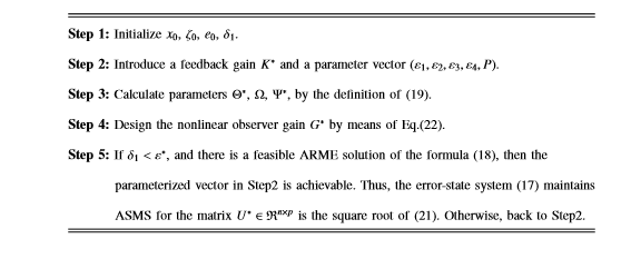
Table 1 Systematic design algorithm of nonlinear observer with a known feedback gain
Remark 1: From Theorem 2, it should be pointed out that, the present design algorithm of nonlinear observer is convergence, since sufficient and necessary conditions of the design of the expected nonlinear observer gain G∗ with a known feedback gain K∗ are guaranteed in the structure of (13) satisfied with (22), to make the error-state system (17) be ASMS for an arbitrary orthogonal matrix
.
Stability Analysis of the error system for nonlinear observer design with a known feedback gain
In many practice situations, several nonlinear disturbances in the dynamic system of MLFMs are unknown and uncertain. With the consideration of the nonlinear system (6)-(7), the uncertain term ΔB is rely on the control input u(t), several full-order nonlinear state observers under consideration are of the form in.25 Here, a nonlinear state observer is formulated as the following structure,
(27)
Where, the constant matrix K∗ = [K1, K2] for K1, K2 ∈ Rn×n. This matrix is an unknown variable with respect to the system (6)-(7), the resulting closed-loop system is derived as follows:
(28)
Define the error state e(t) = x(t)−x(t), then it follows from the system description of (27)-(28), the definition of the error-state is determined by
(29)
For simplicity, we give the following definitions:
(30)
And combining (28), (29) and noting the above updated matrices defined in (30), therefore, the following augmented system is derived by
(31)
In next subsection, both the existence and the analytical expression of the expected observer will be designed to make the current augment system (31) be ASMS.
Stability analysis of the present augment system
This subsection is devoted to the stability analysis of the present augment system. Taking into account for the nonlinear observer structure of (27), sufficient conditions of ASMS for the augment system (31) are studied by using the following theorem.
Theorem 3: Let the observer parameters G∗. If there exist positive scalars ε5, ε6 > 0, such that the matrix equation
(32)
has a positive definite solution P>0 for a sufficiently small positive constants δ2>0, then the nonlinear error-state system (31) is asymptotically stable in the mean square.
Proof: Choosing Lyapunov function candidate as
the detail proof of Theorem 3 sees in (e.g.,20,24,25) by utilizing Lyapunov stability theory, so we omit this derivation. Note that Theorem 3 offers sufficient conditions of the ASMS of the augment system (31) in the robust nonlinear observer design. The result may be conservative mainly due to the introduction of Eq. (32). Thus, the purpose of the rest of the section is to obtain the solution of the observer gain parameters G∗ and K∗.
Nonlinear observer parameters G∗ and K∗ design of the present augment system
In this subsection, throughout the nonlinear observer structure of (27), the following definitions will be useful in deriving a desired robust nonlinear observer gain G∗ and an unknown feedback gain K∗, such that for the addressed nonlinearity and all admissible uncertainties, the proposed augment system (31) is ASMS.
Nonlinear observer parameters G∗ and K∗ design of the present augment system
In this subsection, throughout the nonlinear observer structure of (27), the following definitions will be useful in deriving a desired robust nonlinear observer gain G∗ and an unknown feedback gain K∗, such that for the addressed nonlinearity and all admissible uncertainties, the proposed augment system (31) is ASMS. Prior to stating one of the main results of this paper, we first give the following definitions for the sake of simplicity:
(33)
Theorem 4: Under Assumptions 3-5, two nonlinear observer gain parameter matrices G∗ and K∗ such that the augmented system (31) is ASMS if and only if there exist sufficiently small positive constants δ3, δ4, and a positive achievable parameter vector (ε5, ε6, ε7, ε8, ε9, P) such that the following algebraic Riccati matrix equalities
(34)
(35)
Holds, respectively, have positive-definite solutions P = diag (P1,P2) with P1 > 0 and P2 > 0, where all the matrices
and
are defined in (33), then the nonlinear observer gains of (27) are parameterized by
(36)
(37)
(38)
Where,
-
is an arbitrary orthogonal matrix (i.e.,
),
is an arbitrary matrix meeting
and Φ∗ is defined in (33);
-
is an arbitrary orthogonal matrix (i.e.,
),
is an arbitrary matrix satisfying
and Ψ∗ is expressed in (33).
Proof: (Necessity) Setting
it is note that Assumption 4 does not lose any generality, so the matrix M2 is of full row rank, and
exist. Simultaneously, some definitions of
are considered in (30), by using the Lyapunov function candidate as
then the time derivative of Y(t) along a given trajectory (31) is governed by
(39)
By adopting from Lemma 1 to Lemma 3, Eq.(39) is replaced by
(40)
Where,
, and
According to Lyapunov theory, the augmented system (31) is ASMS for the addressed nonlinearity as well as all admissible uncertainties if only and if the inequality (40) is strictly less than zero. Fortunately, noting that the definition (33) and the sufficient conditions of Theorem 3, if the ARME (34) is implemented into inequality (40), then we obtain
. Observing from the definition of positive matrix P, non-diagonal elements of (32) will be equal to zero, thus it is easy to get Σ12 = 0. Moreover, once the ARME (35) is true, it implies that
. Subsequently, there is
. Therefore, the necessity proof of this theorem is to an end. (Sufficiency) The following derivation is focused on designing of the unknown feedback gain
and the nonlinear observer gain G∗, by developing the following discussion.
- Considering of the definition (33), Σ12 = 0 is replaced by
(41)
In term of Σ12 by the formula (33) and P2 > 0, K2 is estimated as Eq. (37), where the existence of a positive constant q ∈ [0, 1) is to make the matrix
remain invertible.
- By resorting Σ11, Φ∗, and
in the definition (33), and substituting Σ11 into Eq. (34), the expression Σ11 is rearranged
(42)
In the light of the orthogonality of
, and the definition
and
of (33), it is easy to observe that
(43)
Instead of the matrix equality (42),
(44)
for
. By the definition of
, Eq.(36) follows immediately.
- By using the definitions of Σ22, Ψ∗, and Θ∗ in (33), substituting (37) into Σ22, the expression (35) Is re-expanded by
(45)
This can be equivalently expressed by
(46)
Further, when the achievable parameter vector (ε5, ε6, ε7, ε8, ε9, P) is given, we take the square root decomposition
(47)
and then (46) holds if and only if
(48)
Therefore, Eq. (38) follows immediately, for the arbitrary
. The proof of this theorem is completed. From Theorem 4, a modified nonlinear observer design algorithm with an unknown feedback gain is presented in Table 2.
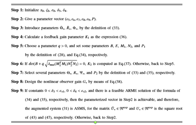
Table 2 Systematic design algorithm of nonlinear observer with an unknown feedback gain.
Remark 2: Throughout the design approach of the desired nonlinear observer gain parameters G∗ and K∗ in Theorem 4, the algorithm described in Table 2 is convergence, since the nonlinear augmented system (31) can be proven to maintain ASMS for the addressed nonlinearity and all admissible uncertainties. More importantly, sufficient and necessary conditions of the desired nonlinear observer with an unknown feedback gain can be designed and derived from the developed theory. As a result, structure parameters G∗ and K∗ of the desired nonlinear observer (27) can be selected from the algebraic Riccati equations (36)-(38), for appropriate arbitrary orthogonal matrices
and
.
Numerical examples
In this section, for the purpose of illustrating the usefulness of the theory developed, two simulation examples are presented. The first example considers stability analysis of the error state system (17) as well as nonlinear observer gain G∗ design. Further, the second example investigates stability analysis of the augment system (31) and nonlinear observer gain parameters G∗ and K∗ design.
Example 1: Consider the nonlinear uncertain stochastic system (13)-(17)
Choose appropriate parameters as ε1 = 0.5256, ε2 = 0.5256, ε3 = 8.7729, ε4 = 8.7729, δ1 = 0.0001, and feedback gain K∗ = 10. Then, by solving the Riccati equation (18), we obtain
Furthermore, substituting V∗ = 1 into (21) yields the desired nonlinear observer gains
On the other hand, the result obtained in24 is recorded
Subsequently, the values of nonlinear observer gain with a known feedback gain for the error state system (17) are shown in Table 3 through comparing with the results of the method presented in.24 From Table 3, it can be concluded that
Methods |
Feedback Gain |
Nonlinear Observer Gain |
Theorem 2 |
K* |
G* |
24 |
K* |
Gw* |
Table 3 Obtained nonlinear observer gain by comparing to the method in24
- G∗ obtained by Theorem 2 is better than the obtained by the approach in;24
- The results obtained by the method of Theorem 2 are better when G∗ is larger.
Hence, the mentioned conclusion implies that G∗ is larger, the nonlinearity and uncertainty degree of the proposed system is higher, for the expected nonlinear observer (13), so that some transient performance requirements (e.g., achievablity, ASMS) are easier to be satisfied. In the Table 1 framework, for the desired nonlinear observer G∗ in Table 3 with a known feedback gain, the dynamics of error-state system (17) is shown in Figure 2.
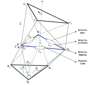
Figure 2 Single VGT module of flexible manipulator.
The error e defined in (15) between the desired trajectory x and the estimated , is a vector of auxiliary signal. It is seen from Figure 3 that the error-state is asymptotically convergence to zero-dynamics, which illustrates that the closed-loop system (17) is stable. So the effectiveness of the developed theory (e.g., Theorem 1 and Theorem 2) is verified.
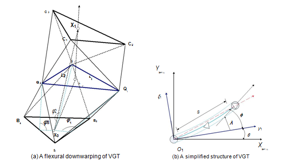
Figure 3 An equivalent simplified structure of VGT flexible module.
Example 2: Consider the nonlinear augment system (27)-(31) with parameters.
We can choose some sufficient small positive constants ε5 = 0.8055, ε6 = 10.1072, ε7 = 12.4537, ε8 = 17.7075, ε9 = 75.3355, δ3 = 0.0001, δ4 = 0.0001. Then the positive definite solution P1 to the matrix Riccati equation (34) and matrices
,
are given by
Further, by the use of expressions (36), (38) for the orthogonal matrix
, a positive definite solution P2 to meet the Riccati matrix equality (35), and matrices Θ∗, R∗ are presented by
Therefore, the structure parameters as G∗ and K∗ of the desired nonlinear observer design in (27), are obtained
respectively. In the Table 2 framework, for the desired nonlinear observer gain G∗ with an unknown feedback gain K∗ in the structure of (27) satisfied with (36-38), the dynamics of augment-state system (31) is displayed in Figure 4 & 5. It is seen from both Figure 4 & 5 that the augment-state system is asymptotically convergence to zero-dynamics, which implies that the closed-loop system (31) is stable. Therefore, the proposed theory (e.g., Theorem 3 and Theorem 4) is reasonable. It is worth noting that sufficient and necessary conditions of the nonlinear observer G∗ with an unknown feedback gain K∗ are obtained as the parameterized expressions (36-38) in the structure of (27). As a result, from Theorem 4, the design of nonlinear observer with an appropriate parameter achieve vector can be guaranteed, such that the proposed system (31) meets the desired transient performance requirements (e.g., achievability, ASMS) Figure 6.

Figure 4 The error trajectories of the present error-state system (17) with e1 (solid) and e2 (dashed).
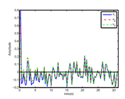
Figure 5 The state trajectories of the proposed augment system (31) with x1 (solid), x2 (point), x3 (Dashed).
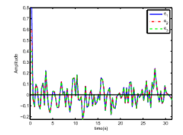
Figure 6 The error trajectories of the proposed augment system (31) with e1 (solid), e2 (point), e3 (Dashed).
Conclusion
In this paper, by utilizing several parameterized achievable conditions for stability analysis of a class of MLFMs, nonlinear observer design problem is discussed. First, by dynamic modeling of the flexible manipulator, an uncertain nonlinear system is unfolded. In a unified ARME framework, to derive sufficient and necessary conditions of ASMS for the proposed system with appropriate nonlinear observers, an error-state system with a known feedback gain and one expansion augment system with an unknown feedback gain is designed, respectively. Moreover, two systematic nonlinear observers design algorithms are presented in Tables 1 & 2. To illustrate the effectiveness of the developed theory, two numerical examples are demonstrated.
Acknowledgment
The author would like to thank the editor(s) and anonymous reviewers for their constructive comments which helped to improve the present paper. This paper is jointly supported by the Natural Science Foundation of China (Grant 61175028, Grant 61374161), and the Key Project of Natural Science Foundation of Shanghai (16JC1401100).
Conflict of interest
Author declares that there is none of the conflicts.
References
- Martinez JIM, Sawut U, Nakano K. Application of non–linear observer with simultaneous perturbation stochastic approximation method to single flexible link SMC. SICE Conference. 2008. p. 2150–2155.
- Caverly RJ, Forbes JR. Dynamic modeling and no collocated control of a flexible planar Cable–driven manipulator. IEEE Trans Robot. 2014;30(6):1386–1397.
- Jiang JJ, Franco PD, Astolfi A. Shared control for the kinematic and dynamic models of a mobile robot. IEEE Trans Contr Syst Technol. 2016;24(6):2112–2124.
- Robert LW II. Kinematic modeling of a double octahedral variable geometry truss (VGT) as an extensible Gimbal. NASA Technical Memorandum. 1994. 109127.
- Vakil M, Fotouhi R, Nikiforuk P. Maneuver control of the multilink flexible manipulators. Int J NonLin Mech. 2009;44(8):831–844.
- Caverly RJ, Forbes JR, Mohammadshahi D. Dynamic modeling and passivity–based control of a single degree of freedom cable–actuated system. IEEE Trans Contr Syst Technol. 2015;23(3):898–909.
- Wang Z, Zeng H, Ho DWC, et al. Multiobjective control of a four–link flexible manipulator: A robust H∞ IEEE Trans Contr Syst Technol. 2002;10(6):866–875.
- Wu HN, Shi P. Adaptive variable structure state estimation for uncertain systems with persistently bounded disturbances. Int J Robust Nonlin Control. 2010;20(17):2003–2015.
- Wang Z, Burnham KJ. Robust filtering for a class of stochastic uncertain nonlinear time–delay systems via exponential state estimation. IEEE Trans Signal Processing. 2001;49(4):794–804.
- Chen SH, Fu LC. Output feedback sliding mode control for a Stewart platform with a nonlinear observer–based forward kinematics solution. IEEE Trans Contr Syst Technol. 2013;21(1):176–185.
- Zhao Y, Gupta V. Feedback passivation of discrete–time systems under communication constraints. IEEE Trans Autom Control. 2016;61(11):3521–3526.
- Mauroy A, Mezic I. Global stability analysis using the eigenfunctions of the Koopman operator. IEEE Trans Autom Control. 2016;61(11):3356–3369.
- Driscoll FR, Lueck RG, Nahon M. Development and validation of a lumped–mass dynamics model of a deep–sea ROV system. Appl Ocean Res. 2000;22(3):169–182.
- Zhang Y, Agrawal SK. Lyapunov controller design for transverse vibration of a cable–linked transporter system. Multibody Syst Dyn. 2006;15(3):287–304.
- De Jalon JG, BayoE. Kinematic and dynamic simulation of multibody systems: the real–time challenge. Springer–Verlag. 1994.
- Ulrich S, Sasiadek JZ, Barkana I. Nonlinear adaptive output feedback control of flexible–joint space robot manipulators. AIAA Guidance Navigation Control Conf. 2013. p. 19–22.
- Jiang T, H Wu. A framework for stability analysis of high–order nonlinear systems based on the CMAC method. Sci China Inform Sci. 2016;59(11):112201.
- Kuljaca O, Horvat K, Horvatek H. Adaptive neural network controller with linear observer for thermal power system frequency control. Eur Control Conf. 2013. p. 1504–1511.
- Lin CF, Su WC. Linear observer design using the inverse method for systems with matched disturbances. American Control Conf. 2010. p. 617–622.
- Hinamoto T, Doi A, Lu WS. Optimal error feedback and realization for roundoff noise minimization in linear discrete–time systems with full–order state observer feedback. IEEE Int Symposium Circuits and Systems. 2015. p. 2956–2959.
- WZhang, HS Su, Y Liang, et al. Non–linear observer design for one–sided Lipschitz systems: a linear matrix inequality approach. IET Control Theory Appl. 2012;6(9):1297–1303.
- Tian E, Wong WK, Yue D, et al. H∞ filtering for discrete–time switched systems with known sojourn probabilities. IEEE Trans Autom Control. 2015;60(9):2446–2651.
- Li B, Zhang X. Observer–based robust control of (0<α<1) fractional–order linear uncertain control systems. IET Control Theory Appl. 2016;10(14):1724–1731.
- Wang Z, Unbehauen H. Nonlinear observers for a class of continuous–time uncertain state delayed systems. Int J Syst Sci. 2000;31(5):555–562.
- Ekramian M, Hosseinnia S, Sheikholeslam F. General framework in designing Luenberger–like non–linear observer. IET Control Theory & Applications. 2013;7(2):253–260.

©2017 Xu, et al. This is an open access article distributed under the terms of the,
which
permits unrestricted use, distribution, and build upon your work non-commercially.


![]() , is a vector of auxiliary signal. It is seen from Figure 3 that the error-state is asymptotically convergence to zero-dynamics, which illustrates that the closed-loop system (17) is stable. So the effectiveness of the developed theory (e.g., Theorem 1 and Theorem 2) is verified.
, is a vector of auxiliary signal. It is seen from Figure 3 that the error-state is asymptotically convergence to zero-dynamics, which illustrates that the closed-loop system (17) is stable. So the effectiveness of the developed theory (e.g., Theorem 1 and Theorem 2) is verified. 
