
Research Article Volume 6 Issue 1
Kinematic and dynamic analysis of a scho?nflies parallel manipulator with horizontal rotation axis
Pegah Ghaf Ghanbari, Mostafa Taghizadeh, Mahmood Mazare
Regret for the inconvenience: we are taking measures to prevent fraudulent form submissions by extractors and page crawlers. Please type the correct Captcha word to see email ID.

School of Mechanical Engineering, Shahid Beheshti University, Iran
Correspondence: Mahmood Mazare, School of Mechanical Engineering, Shahid Beheshti University, Tehran, Iran
Received: November 16, 2019 | Published: February 28, 2020
Citation: Ghanbari PG, Taghizadeh M, Mazare M. Kinematic and dynamic analysis of a scho?nflies parallel manipulator with horizontal rotation axis. Int Rob Auto J . 2020;6(1):42?51. DOI: 10.15406/iratj.2020.06.00200
Download PDF
Abstract
This paper addresses the kinematic and dynamic analysis of a 4-DOF parallel manipulator with Schönflies motion, designed for pick-and-place applications. Its low inertia makes it a suitable choice for pick-and-place applications, which demands high velocity and acceleration. So, the dynamic characteristics of the robot are of high importance. Kinematic analysis is performed via geometric method. After extracting the constraint equations, velocity analysis is performed and Jacobian matrices are evaluated. Using the constraint equations and joint limits, reachable workspace is determined applying point-to-point search algorithm and the existing singularities are identified by the inverse and direct Jacobian matrices. For dynamic modeling, Euler-Lagrange formulation and Virtual work principle are applied. To verify the validity of the extracted kinematic and dynamic model, first the mechanism is designed in CATIA and then imported in ADAMS software. Simulation results of the extracted models are compared to ADAMS model.
Keyword: high-speed parallel robot, schönflies motion generator, kinematics, dynamics
Introduction
Parallel manipulators have proven their superiority over the conventional serial ones, in terms of high accuracy, velocity, stiffness, payload capacity and great dynamic performance.1,2 Although early generation benefited from 6-DOF, nowadays mechanisms with less degrees of freedom are preferred, thanks to their simpler structure, less complex kinematics and dynamics and lower manufacturing cost.3 Pick-and-place which accounts for a great portion of industrial robotic applications require three translational and one rotational motion (3T1R), called Schönflies or SCARA1 motion. 4-DOF parallel robots utilizing parallelograms in their limbs are a good choice for this application as their light-weight; low-inertia structure is compatible with its requirements.
Two eminent high-speed and high acceleration Schönflies parallel robot in the market are Delta robot and Adept Quattro. The former4 consists of three identical R-(SS)2 limbs, generating translational motion of the end-effector in three spatial directions, and a forth telescopic limb, providing the rotational motion about the vertical axis. Evolved from H4,5 I4,6 and Par47 designs, Adept Quattro8 employs four identical R-(SS)2 limbs with an articulated traveling plate to generate the rotation about the vertical axis by an angular amplification device. Recently developed X4,9 uses a single platform structure and can produce ±90° rotation. Four identical arms are connected to the end-effector via four revolute joints whose rotation axes are parallel to a common vertical axis, forming R-(SS)2-R arms. These robots are able to generate rotational motion about the vertical axis. In this paper, a schönflies-motion parallel robot, which is a modification on Veloce redundantly actuated pure 3-DOF translational parallel robot10 is studied. This manipulator is able to produce rotational motion around a horizontal axis and can be an option to fill the existing gap in the industry for such a robot.
Aside from all positive points of parallel robots, their design, analysis, and manufacturing are complicated due to the presence of constraints imposed by their closed kinematic chains. For this reason, their kinematic and dynamic analysis has been the subject of numerous research works. Song,11 Li,12 and Mazare13 focused on kinematic analysis of parallel robots. For dynamic modeling of these robots, various approaches have been applied including Newton-Euler method,14,15,16 Euler-Lagrange formulation,17,18 principle of virtual work,19,20,21 Kane method,22,23 Gibbs-Appel formulation, and Hamilton method.24
Mazare, et al25 derived the dynamic model of a 3-DOF parallel robot by Euler-Lagrange formulation and principle of virtual work and investigated the computation time for solving the inverse dynamic problems. They qualitatively validated the results by means of work-energy and impulse-momentum methods. Li and Xu26 investigated the dynamics of a 3-PRS parallel mechanism using these two approaches. By introducing a simplifying hypothesis, a simplified dynamic model was set up based on principle of virtual work, and it was demonstrated that simplified dynamic model is reasonable under such kind of assumptions. Brinker, et al27 compared the complete and simplified dynamic models of delta robot in terms of computation times and accuracy. Three approaches were applied to derive dynamic formulations, including Newton-Euler method, principle of virtual work, and Euler-Lagrange formulation. In spite of the fact that capability and efficiency of high-speed pick-and-place parallel robots is directly related to their dynamic characteristics and controller, a proper trajectory planning also plays a crucial role in smooth torques, low energy consumption, low residual vibrations and short cycle times.28,29
Gallant, et al30 showed that payload capacity of a robot is affected by the trajectory it follows. Khoukhi, et al31 solved the trajectory planning problem of a robot using a variational calculus framework. They Considered robot kinematic and dynamic models, while optimizing execution time and required, avoiding singularities and satisfying several constraints related to the robot, task and workspace. Gasparetto, et al32 suggested a new approach to optimize the trajectory of robot manipulators for minimum integral of the squared jerk and execution time. To compose the overall trajectory, quantic B-spline curves were utilized which produces continuous position, velocity, and acceleration profiles. Similarly, making use of quantic B-spline curves and exploiting the symmetric properties of the path, Li, et al33 proposed a new approach for optimal smooth trajectory planning of high-speed pick-and-place parallel robots and compared the resulting input torques and residual vibrations of the manipulator with the trajectories obtained from Lamé curves and piecewise polynomials.
The rest of the paper is organized as follows. In section 2 the parallel manipulator is presented. Section 3 deals with the kinematic problem, while in section 4 the dynamic models of the robot are derived based on Euler-Lagrange formulation and principle of virtual work. Section 5 describes trajectory the generated for pick-and-place application, employing quintic B-splines. Section 6 is devoted to designing a PD controller. Section 7 presents the simulation results for both dynamic models and compares them to ADAMS output to validate the models and present the superior performance of the chosen trajectory. Conclusions are derided in section 8.
1Selective Compliance Assembly Robot Arm
Manipulator description
The mechanism under review is a modification on redundantly actuated Veloce manipulator, comprising of four identical R-(SS)2 arms, connecting the base to the end-effector. By shifting the connection of the two opposite arms to the end-effector along opposite directions and adding two revolute joints as shown in Figure 1, the mechanism will be able to generate Schönflies motion, with its rotation around horizontal axis.34
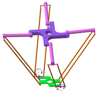
Figure 1 CAD model of Schönflies motion robot.
Kinematics
The structure of one arm of the manipulator is illustrated in Figure 2. The base frame , is attached to the geometric center of the fixed platform defined by revolute joints ( ), with its direction pointing toward and its direction normal to the plane of the fixed platform. Similarly, the moving frame , is set at the geometric center of the moving platform, with its direction crossing point and its direction perpendicular to the plane formed by , representing the attaching points of the arms to the end effector. is the rotation axis of the end effector and it always remains parallel to Y.
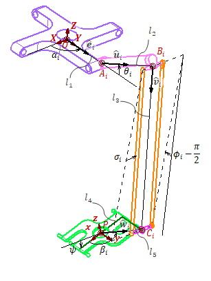
Figure 2 Coordinate frames and variables of the arm.
Position kinematics
The loop-closure equation for the ith arm is written as
(1)
(2)
Rearranging this equation and squaring both sides results in
(3)
which yields the constraint equations of the manipulator as
(4)
where
is the end effector pose, and
is the active joint variables.
is the only vector dependent on
and is defined by
(5)
Introducing (5) to equations (3) yields
(6)
(7)
The solution to the second-degree equation (6) is the inverse kinematic equation of the robot, written as
(8)
Velocity analysis
The key element of velocity analysis is Jacobian matrix, which is a mapping between the joint velocities to the velocity of the end-effector. To derive this matrix, eq.(1) is differentiated with respect to time.
(9)
where
and
are the angular velocity of the upper and lower links of the ith arm, respectively. Taking the dot product of both sides of eq.(9) with and considering
, we obtain
(10)
This gives the mapping between the velocity of the ith active joint and the end effector, which can be written in matrix form.
(11)
(12)
Obviously, the velocity equation for the whole manipulator will be
(13)
where
represents the vector of active joints angular velocity.
Now assuming that the center of mass of the upper link is located in the middle of
, the linear velocity of the point
can be determined from
(14)
Workspace analysis
Reachable workspace refers to areas of space that the end-effector central point can access regardless of orientation. The constraints for determining the robot workspace embody the connection between the arms, the performance range of the joints, the length of the links, and the internal correlations. In this research, numerical method is used to extract the workspace of the studied robot and the following constraints are applied to the joints.
(15)
Where
is the angle of upper and lower links in each chain. Figure 3– depicts the workspace of the robot in three distinct rotations.
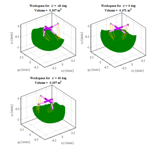
Figure 3 Constant orientation workspace.
Dynamics
For dynamic modeling of the manipulator, both the principle of virtual work and Euler-Lagrange formulation are used. As the rotational inertia of the lower links is negligible, in both approaches, they are considered as point masses on their both extreme ends.
Virtual work principle
Force system of the ith arm can be written as
(16)
(17)
In which is the gravity vector,
is the moment of inertia of the ith upper link about its center of mass with respect to base coordinate frame, . Force system of the end-effector is deduced as
(18)
Where
is the moment of inertia of the end-effector and
is the external wrench applied to it.
Extending the principle of the virtual work from the static to the dynamic case with the D’Alembert’s principle, we can get
(19)
where
is the torque applied by the actuators, and
is the virtual displacement of the ith arm.
Referring to the kinematic analysis, the virtual displacements can be obtained as
(20)
(21)
Substituting the deduced forces and virtual displacements into eq.(21) yields the inverse dynamics of the manipulator.
(22)
(23)
(24)
(25)
(26)
Euler-lagrange formulation
For modeling a dynamic system using Euler-Lagrange formulation, the first step is determining the Lagrangian, which is defined as the difference between kinetic energy and potential energy of the system. In this section, we neglect the inertia of the lower links and consider them as point masses on their both extreme ends. So, the variables will be active joints variables
and end effector pose X.
(27)
Potential energy is caused by conservative forces acting on the system. Here, the only conservative force is gravity. So, the potential energy of the arms is written as
(28)
And the potential energy of the end-effector is obtained from
(29)
The potential energy of the manipulator is deduced from adding the potential energy of its subsystems.
(30)
The kinetic energy of the arms is a function of active joints variable, and is determined by
(31)
The kinetic energy of the end effector is obtained from
(32)
Where
(33)
The kinetic energy of the manipulator is obtained from adding the kinetic energy of the arms and the end-effector.
(34)
As is obvious, the Lagrangian can be written as the contribution of the two subsystems, each one depending on its own variables, though connected together via constraint equations. This helps us with deriving two sets of dynamic equations using 1st type of Lagrange formulation.
The dynamic model of the arms is calculated from
(35)
where,
is the vector of Lagrange multipliers, and f represents the constraint equations of the manipulator. This yields the following equations
(36)
(37)
(38)
Similarly, the dynamic model of the end-effector is calculated by
(39)
This results in the following dynamic equations.
(40)
(41)
In order to calculate the dynamic model of the whole manipulator, these two models need to be combined by cancelling the Lagrange multipliers. To do so, eq.(35) is solved for and the result is introduced to eq.(39).
(42)
Differentiating eq.(3) with respect to time, we obtain
(43)
Solving this equation for results in
(44)
Comparing eq.(13) and eq.(43), we can infer that
(45)
Substituting eq.(44) into (41) gives the dynamic model of the manipulator in workspace.
(46)
(47)
(48)
(49)
(50)
Trajectory planning
PnP operations are usually performed in an environment free of obstacles, as a result just initial and end points of the path are important. However to have more control on departure and arrival, we define some via points as shown in Figure 4. Here, -axis is parallel to Z-axis of the
coordinate frame; and V-axis is located in
plane.
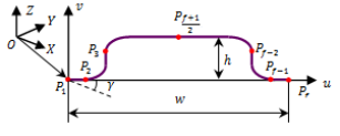
Figure 4 PnP path defined in a local frame.
Any point on the path in defined in the local coordinate can be transformed to the base coordinate frame as follows.
(51)
Where,
is the rotation angle of local frame with respect to the fixed frame. Parameters defining the path are
(52)
(53)
(54)
A B-spline of degree pnbsp;and order
is a linear combination of polynomials
of degree p, called base or blending functions, weighted by control points ,
. represents a normalized independent parameter here taken as the time. Then, the normalized motion profile
is then formed as
(55)
The base function is defined recursively by means of the De Boor formula.35
(56)
is a sequence of nodes on which
is built by interpolation. The rth derivative of B-spline is calculated from
(57)
Where
represents the control points of the rth derivative of
and can be deduced recursively by
(58)
In order for the control points to coincide with the initial and final via-points, the nodes at both ends of the trajectory must be repeated
times. Moreover, to obtain trajectories with no jerk at both ends, two virtual points is introduced at the second and second-last position of the node sequence. With these considerations, the number of nodes and the number of control points will be
and
respectively.
A B-spline of degree p has
-continuity, so for the trajectory to be smooth in terms of jerk, it is necessary to choose
. Therefore,
and
. In order to guarantee that the trajectory passes through the via-points, the following equations must be satisfied.
(59)
Imposing boundary conditions for velocity, acceleration and jerk at both ends of the trajectory results in six constraint equations as
(60)
can be deduced from (59) and (60) recursively. To calculate the control points of the desired trajectory, equations (61) and (62) are written in matrix form, yielding
(61)
Where
(62)
(63)
(64)
(65)
(66)
For this problem, we choose
via-points as follows
(67) where
and
are the ratio of the
coordinate of
and
to the corresponding coordinate of the final point, respectively, and obviously,
. Moreover,
is the ratio of the
coordinate of
to the corresponding coordinate of the mid-point. Therefore, the sequence of nodes will be
(67)
Three-time ratio are defined as
(68)
where
is the ratio between the time the end-effector spends to move from p1 to p2 and the time from p1 to p4.
represents the ratio between the time the end-effector spends to move from
to
and the time from
to
. denotes the ratio between the time the end-effector spends to move from
to
and the time from
to
. To maintain the correct order of the nodes, the condition
must be met. The symmetry of the path allows expressing the nodes in terms of
,
and
.
(69)
Now, position vector of any point on the path can be deduced from
(70)
Where subscripts ‘
’ and ‘
’ stands for motion profile along the horizontal and vertical axis in local frame.
is the time taken by the end-effector to move from the initial to the final point. Considering
and
, while
(71)
We can determine the control points from eq.(63).
Dimensionless position, velocity, acceleration and jerk of any point on the path can be determined by normalizing the position and its derivatives by
.
(72)
Cycle time, T, is limited by the speed and torque constraint of the motors. According to Li, et al33 it can be proved that the cycle time must be subject to
(73)
Trajectory optimization problem
As the peak values and smoothness of the time histories of the active joint torques are directly related to those of acceleration and jerk of the end-effector at non-singular configurations, we can optimize the trajectory in the Cartesian space using appropriate performance indices based on acceleration and jerk of the end-effector.36 Li, et al33 proposed a pair of performance indices for evaluating acceleration and jerk of the end effector over the entire normalized path within the normalized time duration as
(74)
The multi-objective optimization problem for the smooth trajectory is formulated as:
Minimize
;
Minimize
Minimize
Minimize
Over
(75)
Subject to
Finally, the PnP trajectory in the workspace of the robot is depicted in Figure 5.
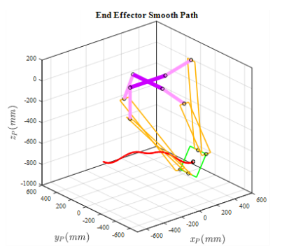
Figure 5 Robot reference PnP path.
Simulation results
To ensure the accuracy of the extracted kinematic and dynamic equations, the robot mechanism is simulated in the ADMS software, and its output is compared to the results obtained from the extracted equations. Reference trajectory components in task space are determined and illustrated in Figure 6. To verify the validity of the inverse dynamics model, the acceleration corresponding to the reference trajectory is applied to the mathematical model, and the torque of the actuators as the output of the dynamic model is compared with the ADAMS slightly different. simulation output. The results presented in Figure 7 demonstrate similar behavior, although the torque size is
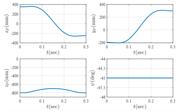
Figure 6 Robot reference PnP path.
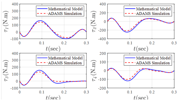
Figure 7 Active joints torques.
The slight difference between the two distinct simulations arises from the assumptions that are included in system modeling. The first assumption was to place the center of gravity of the upper links in the center of the line along the center of their hinges on both ends. However, in the ADAMS model, the center of gravity deviates slightly from this point. The second hypothesis is ignoring the inertia of the lower links of the arms, which their effects are modeled as two identical lumped masses at the two ends of the links.
To solve the inverse kinematics of the robot, the input (reference trajectory) is applied to the end-effector and the angles of the active joints are calculated. Figure 8 shows the strict conformity of the results of the inverse kinematics analytically to the results of the mechanism simulated in the ADAMS.
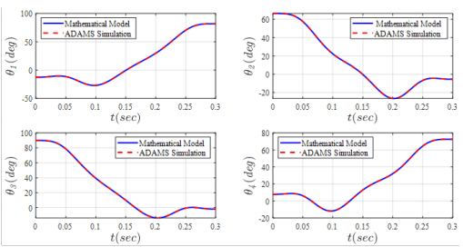
Figure 8 Joint space components by solving inverse kinematics.
In addition, in order to solve the forward kinematic problem, the angles of the active joints obtained from the inverse kinematic problem, are applied as inputs to the active joints. The results shown in Figure 9 which reveal a good agreement between the analytical method and the ADAMS model.
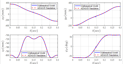
Figure 9 Task space components by solving forward kinematics.
Conclusion
The purpose of this paper was to evaluate the kinematic and dynamic performance of a four-degree-of-freedom robot generating Schönflies motion. Three translational and one rotational degrees of freedom makes this robot a good option for pick-and-place applications where high speed and acceleration are required. The studies began with extracting the kinematic equations of the robot based on the geometric method, followed by velocity analysis. Using extracted kinematic equations as well as joint constraints, the robot workspace was numerically determined. In the next step, the governing dynamics equations of this mechanism were extracted using Euler-Lagrange method for constrained systems, since the robot under study is a parallel equations, the robot was modeled in ADAMS mechanism whose main characteristic is being constrained. In order to validate the kinematic and dynamic software, and the results of numerical solution of the aforementioned equations, were compared with the ADAMS output.
Funding
Acknowledgments
Conflicts of interest
The authors declare that there was no conflict of interest.
References
- Yang G, Chen IM, Lin W, et al. Singularity analysis of three–legged parallel robots based on passive–joint velocities. IEEE Transactions on Robotics and Automation. 2001;17(4):413–422.
- Y Wang. An Incremental Method for Forward Kinematics of Parallel Manipulators. Proceedings of IEEE International Conference on Robotics, Automation and Mechatronics; 2006 Jun 1-3; Thailand. Bangkok: IEEE; 2006.
- Dai JS, Lipkin H, Huang Z. Mobility of overconstrained parallel mechanisms. ASME Journal of Mechanical Design. 2006;128(1):220–229.
- R. Clavel. Une nouvelle structure de manipulateur parallèle pour la robotique légère. APII. 1989;23(6):501–519.
- Pierrot F, Marquet F, Company O, et al. H4 parallel robot: modeling, design and preliminary experiments. Proceedings 2001 ICRA. IEEE International Conference on Robotics and Automation; 2001 May 21–26; South Korea: IEEE; 2001.
- Krut S, Benoit M, Ota H, et al. I4: A new parallel mechanism for Scara motions. 2003 IEEE International Conference on Robotics and Automation (Cat. No.03CH37422); 2003 Sept 14-19; Taipei. Taiwan: IEEE; 2003.
- Nabat V, Rodriguez O, Company O, et al. Par4: very high speed parallel robot for pick–and–place. 2005 IEEE/RSJ International Conference on Intelligent Robots and Systems; 2005 Aug 2–6; Edmonton. Canada: IEEE; 2005.
- Pierrot F, Nabat V, Company O, et al. Optimal Design of a 4–DOF Parallel Manipulator: From Academia to Industry. IEEE Transactions on Robotics. 2009;25(2):213–224.
- Xie F, Liu X. Design and Development of a High–Speed and High–Rotation Robot With Four Identical Arms and a Single Platform. Journal of Mechanisms and Robotics. 2015;7(4):041015.
- http://pentarobotics.com/products/#brochure.
- Song Y, Gao H Sun T, et al. Kinematic analysis and optimal design of a novel 1T3R parallel manipulator with an articulated travelling plate. Robotics and Computer–Integrated Manufacturing. 2014;30(5):508–516.
- A Novel Three–Loop Parallel Robot With Full Mobility: Kinematics, Singularity, Workspace, and Dexterity Analysis. ASME Journal Mechanisms Robotics. 2017;9(5):051003.
- Mazare M, Taghizadeh M, Najafi M. Kinematic analysis and design of a 3–DOF translational parallel robot. International Journal of Automation and Computing. 2017;14(4):432–441.
- Khalil W, Ibrahim O. General Solution for the Dynamic Modeling of Parallel Robots. Journal of Intelligent and Robotic Systems. 2007;49(1):19–37.
- Shao ZF, Tang X, Wang L. Dynamics verification experiment of the Stewart parallel manipulator. International Journal of Advanced Robotic Systems. 2015;12(144):1–10.
- Wang Z, Zhang N, Chai X, et al. Kinematic/dynamic analysis and optimization of a 2–URR–RRU parallel manipulator. Nonlinear Dynamics. 2017;88(1):503–519.
- Abdellatif H, Heimann B. Computational efficient inverse dynamics of 6–DOF fully parallel manipulators by using the Lagrangian formalism. Mechanism and Machine Theory. 2009;44(1):192–207.
- Tsai MS, Yuan WH. Dynamic Modeling and Decentralized Control of a 3 PRS Parallel Mechanism Based on Constrained Robotic Analysis. Journal of Intelligent & Robotic Systems. 2011;63(3–4):525–545.
- Zhao Y, Gao F. Inverse dynamics of the 6–dof out–parallel manipulator by means of the principle of virtual work. Robotica. 2009;27(2):259–268.
- Li Y, Xu Q. Dynamic modeling and robust control of a 3–PRC translational parallel kinematic machine. Robotics and Computer–Integrated Manufacturing. 2009;25(3):630–640.
- Zhao Y, Zhang Z, Cheng G. Inverse rigid–body dynamic analysis for a 3UPS–PRU parallel robot. Advances in Mechanical Engineering. 2017;9(2):1–14.
- Yang C, Huang Q, Jiang H,et al. PD control with gravity compensation for hydraulic 6–DOF parallel manipulator. Mechanism and Machine Theory. 2010;45(4):666–677.
- Yang C, Huang Q, Han J, et al. Decoupling control for spatial six–degree–of–freedom electro–hydraulic parallel robot. Robotics and Computer–Integrated Manufacturing. 2012;28(1):14–23.
- Miller K. Optimal Design and Modeling of Spatial Parallel Manipulators. Journal of Robotics Research. 2004;23(2):127–140.
- Mazare M, Taghizadeh, Najafi MR. Inverse Dynamics of a 3–P[2(US)] Translational Parallel Robot. Robotica. 2018;1–21.
- Li Y, Xu Q. Kinematics and inverse dynamics analysis for a general 3–PRS spatial parallel mechanism. Robotica. 2005;23(2):219–229.
- Jadran L, Jean PM. Advances in Robot Kinematics 2016. Springer Proceedings in Advanced Robotics. 2016:119–128.
- Pellicciari M, Berselli G, Leali F, et al. A method for reducing the energy consumption of pick–and–place industrial robots. Mechatronics. 2013;23(3):326–334.
- Li H, Le MD, Gong ZM, et al. Motion profile design to reduce residual vibration of high–speed positioning stages. IEEE/ASME Transactions on Mechatronics. 2009;4(2):264–269.
- Gallant A, Gosselin C. Extending the capabilities of robotic manipulators using trajectory optimization. Mechanism and Machine Theory. 2018;121:502–514.
- Khoukhi A, Baron L, Balazinski M. Constrained multi–objective trajectory planning of parallel kinematic machines. Robotics and Computer–Integrated Manufacturing. 2009;25:756–769.
- Gasparetto A, Zanotto V. A new method for smooth trajectory planning of robot manipulators. Mechanism and Machine Theory. 2007;42:455–471.
- Li Y, Huang T, Chetwynd DG. An approach for smooth trajectory planning of high–speed pick–and–place parallel robots using quintic B–splines. Mechanism and Machine Theory. 2018;126:479–490.
- Wu G. Kinematic analysis and optimal design of a wall–mounted four–limb parallel Schönflies–motion robot for pick–and–place operations. Journal of Intelligent & Robotic Systems. 2017;85:663–677.
- Piegl W, Tiller W. The NURBS Book. Springer–Verlag: New York; 1997.
- Barre PJ, Bearee R, Borne P, et al. Influence of a Jerk Controlled Movement Law on the Vibratory Behaviour of High–Dynamics Systems. Journal of Intelligent and Robotic Systems. 2005;42(3):275–293.

©2020 Ghanbari, et al. This is an open access article distributed under the terms of the,
which
permits unrestricted use, distribution, and build upon your work non-commercially.


