Submit manuscript...
eISSN: 2574-8092

International Robotics & Automation Journal

Research Article Volume 10 Issue 3

Automatic alignment of elastic slender belt caused by crown roller in two-roller belt system

Kazushi Yoshida, Anjyu Suetomi, Hayato Kawamata, Yu Nakamichi

Department of Mechanical Engineering, Faculty of Engineering, Sanyo-Onoda City University, Japan

Correspondence: Kazushi Yoshida, Department of Mechanical Engineering, Faculty of Engineering, Sanyo-Onoda City University, 1-1-1 Daigaku-Dori, Sanyo-Onoda, Yamaguchi, Japan, Tel +81-831-88-3536

Received: August 13, 2024 | Published: September 2, 2024

Citation: Yoshida K, Suetomi A, Kawamata H, et al. Automatic alignment of elastic slender belt caused by crown roller in two-roller belt system. Int Rob Auto J. 2024;10(3):78-83. DOI: 10.15406/iratj.2024.10.00287

Download PDF

Abstract

To clarify the relationship between the geometry of the crown roller and the automatic alignment of the belt in a two-roller belt system that includes a crown roller, we develop an analytical method that calculates the lateral belt position. The calculated results based on this method are in good agreement with the experimental results, thereby validating the analysis method developed. The automatic alignment of the belt is caused by the difference in the peripheral speed of the crown roller in the axial direction. The automatic alignment effect improves as the radius of curvature and the diameter of the crown roller decrease. Furthermore, we show that the effect of belt tension on the automatic alignment of the belt has a slight effect on the time until the belt moves to the roller center position but does not have a significant effect on the automatic alignment of the belt.

Keywords: automatic alignment, belt system, crown roller, radius of curvatue, lateral belt motion

Introduction

Belt systems including a flat elastic belt and rollers are used for power transmission and transportation. In such belt systems, crown rollers are frequently used to prevent the belt from running off and move the belt toward the center of the roller (hereinafter referred to as automatic alignment). Although crown rollers have been introduced in books and articles on mechanics, the relationship between automatic alignment and roller parameters, such as radius of curvature and diameter of crown rollers, and their effect on automatic alignment are not well understood. To ensure the reliability of a belt system, the relationship between roller parameters and automatic belt alignment need to be clarified.

Many studies have examined the lateral motion of belts or webs such as films and thin sheets.1–4 However, most of these studies have focused on the lateral motion caused by the misalignment angle, and few studies have been conducted on the relationship between automatic alignment and roller parameters. Leikakh formulated an approximate model of lateral stability considering geometrical and mechanical parameters of a belt system including crown rollers.5 In this study, a formula was developed expressing the equilibrium position of the belt, which represented the influence of parameters such as the misalignment angle, radius of curvature of the pulley, and lateral stiffness of the belt in flexure. Egger and Hoffmann developed a simulation method for calculating the lateral motion behavior of a two-roller belt system including non-skewed conical and skewed cylindrical tail rollers.6 The method was based on the beam theory and considered the effect of friction between the conveyor and rollers in the belt system. The results showed that the lateral belt ran out in the direction of the roller with the largest diameter. Cheng et al.,7 studied the relationship between the shape of the crown rollers and belt shift motion of a belt system using the finite element method (FEM) and experiments.7 They showed that when the belt wrapped around the crown rollers, the centerline of the belt between the rollers assumed the shape of an infinity symbol, which caused it to align automatically. Kobayashi and Toya examined the factors affecting the  lateral belt motion in a two-roller belt system including crown rollers by conducting experiments and FEM analysis.8 This study showed that the height of the crown rollers significantly affected the belt motion, in-plane misalignment angle, and distance between the rollers. Dilip and Brice9 developed two analytical models for the belt motion between cylindrical rollers with a misalignment angle and a model for the lateral belt motion over conical rollers.9 The tracking direction and the belt rate could be predicted using these analytical models. However, empirical constants based on experiments were required to predict the equilibrium position of the belt.

Despite these efforts, a method that explicitly expresses the relationship between automatic alignment of a belt and roller parameters has not yet been developed. To achieve highly reliable in belt systems, an analytical method that can explain the relationship between the parameters related to the roller geometry and automatic alignment of the belt must be developed. To develop the method, in our previous study, the relationship between the geometry of the crown roller and lateral belt motion of an open-end belt system was investigated. In addition, we examined the relationship between the lateral motion of the belt and the crown roller parameters.10 This study developed a formula to evaluate the automatic alignment of a belt in a two-roller belt system using geometric parameters of the crown roller, based on the results of our previous study.

Material and methods

Mechanism of automatic alignment

This study aimed to clarify the relationship between the parameters of the crown roller and automatic alignment of the belt of a two-roller belt system including crown and cylindrical rollers. This belt system is shown in Figure 1. The crown roller was driven by a motor, and the cylindrical roller was rotated by the belt movement. On the tight side of the belt, the crown and cylindrical rollers were downstream and upstream rollers, respectively. Conversely, on the slack side of the belt, the crown and cylindrical rollers were the upstream and downstream rollers, respectively.

Figure 1 Two-roller belt system including crown and cylindrical rollers.

Figure 2 shows the set O T x T y T MathType@MTEF@5@5@+= feaagKart1ev2aaatCvAUfeBSjuyZL2yd9gzLbvyNv2CaerbuLwBLn hiov2DGi1BTfMBaeXatLxBI9gBaerbd9wDYLwzYbItLDharqqtubsr 4rNCHbGeaGqipu0Je9sqqrpepC0xbbL8F4rqqrFfpeea0xe9Lq=Jc9 vqaqpepm0xbba9pwe9Q8fs0=yqaqpepae9pg0FirpepeKkFr0xfr=x fr=xb9adbaqaaeGaciGaaiaabeqaamaabaabaaGcbaqcLbsacaWGpb WcdaWgaaqaaKqzadGaamivaaWcbeaakiabgkHiTKqzGeGaamiEaSWa aSbaaeaajugWaiaadsfaaSqabaqcLbsacaWG5bWcdaWgaaqaaKqzad GaamivaaWcbeaaaaa@4203@ and O S x S y S MathType@MTEF@5@5@+= feaagKart1ev2aaatCvAUfeBSjuyZL2yd9gzLbvyNv2CaerbuLwBLn hiov2DGi1BTfMBaeXatLxBI9gBaerbd9wDYLwzYbItLDharqqtubsr 4rNCHbGeaGqipu0Je9sqqrpepC0xbbL8F4rqqrFfpeea0xe9Lq=Jc9 vqaqpepm0xbba9pwe9Q8fs0=yqaqpepae9pg0FirpepeKkFr0xfr=x fr=xb9adbaqaaeGaciGaaiaabeqaamaabaabaaGcbaqcLbsacaWGpb WcdaWgaaqaaKqzadGaam4uaaWcbeaajugibiabgkHiTiaadIhakmaa BaaaleaajugWaiaadofaaSqabaqcLbsacaWG5bWcdaWgaaqaaKqzad Gaam4uaaWcbeaaaaa@4200@ coordinate. The O T x T y T MathType@MTEF@5@5@+= feaagKart1ev2aaatCvAUfeBSjuyZL2yd9gzLbvyNv2CaerbuLwBLn hiov2DGi1BTfMBaeXatLxBI9gBaerbd9wDYLwzYbItLDharqqtubsr 4rNCHbGeaGqipu0Je9sqqrpepC0xbbL8F4rqqrFfpeea0xe9Lq=Jc9 vqaqpepm0xbba9pwe9Q8fs0=yqaqpepae9pg0FirpepeKkFr0xfr=x fr=xb9adbaqaaeGaciGaaiaabeqaamaabaabaaGcbaqcLbsacaWGpb WcdaWgaaqaaKqzadGaamivaaWcbeaakiabgkHiTKqzGeGaamiEaSWa aSbaaeaajugWaiaadsfaaSqabaqcLbsacaWG5bWcdaWgaaqaaKqzad GaamivaaWcbeaaaaa@4203@ and O S x S y S MathType@MTEF@5@5@+= feaagKart1ev2aaatCvAUfeBSjuyZL2yd9gzLbvyNv2CaerbuLwBLn hiov2DGi1BTfMBaeXatLxBI9gBaerbd9wDYLwzYbItLDharqqtubsr 4rNCHbGeaGqipu0Je9sqqrpepC0xbbL8F4rqqrFfpeea0xe9Lq=Jc9 vqaqpepm0xbba9pwe9Q8fs0=yqaqpepae9pg0FirpepeKkFr0xfr=x fr=xb9adbaqaaeGaciGaaiaabeqaamaabaabaaGcbaqcLbsacaWGpb WcdaWgaaqaaKqzadGaam4uaaWcbeaajugibiabgkHiTiaadIhakmaa BaaaleaajugWaiaadofaaSqabaqcLbsacaWG5bWcdaWgaaqaaKqzad Gaam4uaaWcbeaaaaa@4200@ planes are the base planes in which the belt moves on the tight and slack sides, respectively.

Figure 2 Co-ordinate systems in this study.

As shown in Figure 3, when the belt is conveyed and wraps around the crown roller, it tilts as it approaches the crown roller, owing to the difference in the peripheral speed of the crown roller in the y T MathType@MTEF@5@5@+= feaagKart1ev2aaatCvAUfeBSjuyZL2yd9gzLbvyNv2CaerbuLwBLn hiov2DGi1BTfMBaeXatLxBI9gBaerbd9wDYLwzYbItLDharqqtubsr 4rNCHbGeaGqipu0Je9sqqrpepC0xbbL8F4rqqrFfpeea0xe9Lq=Jc9 vqaqpepm0xbba9pwe9Q8fs0=yqaqpepae9pg0FirpepeKkFr0xfr=x fr=xb9adbaqaaeGaciGaaiaabeqaamaabaabaaGcbaqcLbsacaWG5b WcdaWgaaqaaKqzadGaamivaaWcbeaaaaa@39A1@ -direction. Therefore, on the tight side, the belt moves in the y T MathType@MTEF@5@5@+= feaagKart1ev2aaatCvAUfeBSjuyZL2yd9gzLbvyNv2CaerbuLwBLn hiov2DGi1BTfMBaeXatLxBI9gBaerbd9wDYLwzYbItLDharqqtubsr 4rNCHbGeaGqipu0Je9sqqrpepC0xbbL8F4rqqrFfpeea0xe9Lq=Jc9 vqaqpepm0xbba9pwe9Q8fs0=yqaqpepae9pg0FirpepeKkFr0xfr=x fr=xb9adbaqaaeGaciGaaiaabeqaamaabaabaaGcbaqcLbsacaWG5b WcdaWgaaqaaKqzadGaamivaaWcbeaaaaa@39A1@ -direction toward the center of the crown, as shown in Figure 4.

Figure 3 Belt tilt caused by difference in peripheral speed of crown roller.

Figure 4 Belt movement toward roller center on crown roller.

However, on the slack side, the belt does not move in the width direction because the downstream roller is cylindrical. However, after the rollers rotate by half a revolution, the belt position in the width direction of the upstream roller, i.e., the crown roller, changes. As shown in our previous study,10 if the position in the width direction differs between the upstream and downstream rollers, the belt travels in the direction perpendicular to the downstream roller axis. Consequently, the belt position on the downstream roller, i.e., the cylindrical roller, moves in the width direction to become the same as that on the upstream roller, as shown in Figure 5. This movement of the belt toward the center of the rollers is the automatic alignment.

Figure 5 Belt movement toward roller center on cylindrical roller.

Tilt angle of belt due to crown roller configuration

As mentioned above, the belt tilts as it approaches the crown roller, owing to the difference in the peripheral speed of the crown rollers. As shown in our previous study, the tilt angle of a belt approaching a roller with different diameters in the axial direction can be expressed as follows:

θ= 1 B { | 1 2 0 y B +B/2 df( y T ) d y T y T d y T || 1 2 0 y B B/2 df( y T ) d y T y T d y T | } MathType@MTEF@5@5@+= feaagKart1ev2aaatCvAUfeBSjuyZL2yd9gzLbvyNv2CaerbuLwBLn hiov2DGi1BTfMBaeXatLxBI9gBaerbd9wDYLwzYbItLDharqqtubsr 4rNCHbGeaGqipu0Je9sqqrpepC0xbbL8F4rqqrFfpeea0xe9Lq=Jc9 vqaqpepm0xbba9pwe9Q8fs0=yqaqpepae9pg0FirpepeKkFr0xfr=x fr=xb9adbaqaaeGaciGaaiaabeqaamaabaabaaGcbaqcLbsacqaH4o qCcqGH9aqpkmaalaaabaqcLbsacaaIXaaakeaajugibiaadkeaaaGc daGadaqaamaaemaabaWaaSaaaeaajugibiaaigdaaOqaaKqzGeGaaG OmaaaakmaapedabaWaaSaaaeaajugibiaadsgacaWGMbGcdaqadaqa aKqzGeGaamyEaSWaaSbaaeaajugWaiaadsfaaSqabaaakiaawIcaca GLPaaaaeaajugibiaadsgacaWG5bWcdaWgaaqaaKqzadGaamivaaWc beaaaaqcLbsacaWG5bWcdaWgaaqaaKqzadGaamivaaWcbeaajugibi aadsgacaWG5bWcdaWgaaqaaKqzadGaamivaaWcbeaaaeaacaaIWaaa baGaamyEamaaBaaameaacaWGcbaabeaaliabgUcaRmaalyaabaGaam OqaaqaaiaaikdaaaaaniabgUIiYdaakiaawEa7caGLiWoajugibiab gkHiTOWaaqWaaeaadaWcaaqaaKqzGeGaaGymaaGcbaqcLbsacaaIYa aaaOWaa8qmaeaadaWcaaqaaKqzGeGaamizaiaadAgakmaabmaabaqc LbsacaWG5bWcdaWgaaqaaKqzadGaamivaaWcbeaaaOGaayjkaiaawM caaaqaaKqzGeGaamizaiaadMhalmaaBaaabaqcLbmacaWGubaaleqa aaaajugibiaadMhalmaaBaaabaqcLbmacaWGubaaleqaaKqzGeGaam izaiaadMhalmaaBaaabaqcLbmacaWGubaaleqaaaqaaiaaicdaaeaa caWG5bWaaSbaaWqaaiaadkeaaeqaaSGaeyOeI0YaaSGbaeaacaWGcb aabaGaaGOmaaaaa0Gaey4kIipaaOGaay5bSlaawIa7aaGaay5Eaiaa w2haaaaa@8437@ ,         (1)

where B MathType@MTEF@5@5@+= feaagKart1ev2aaatCvAUfeBSjuyZL2yd9gzLbvyNv2CaerbuLwBLn hiov2DGi1BTfMBaeXatLxBI9gBaerbd9wDYLwzYbItLDharqqtubsr 4rNCHbGeaGqipu0Je9sqqrpepC0xbbL8F4rqqrFfpeea0xe9Lq=Jc9 vqaqpepm0xbba9pwe9Q8fs0=yqaqpepae9pg0FirpepeKkFr0xfr=x fr=xb9adbaqaaeGaciGaaiaabeqaamaabaabaaGcbaqcLbsacaWGcb aaaa@372C@ is the belt width, y B MathType@MTEF@5@5@+= feaagKart1ev2aaatCvAUfeBSjuyZL2yd9gzLbvyNv2CaerbuLwBLn hiov2DGi1BTfMBaeXatLxBI9gBaerbd9wDYLwzYbItLDharqqtubsr 4rNCHbGeaGqipu0Je9sqqrpepC0xbbL8F4rqqrFfpeea0xe9Lq=Jc9 vqaqpepm0xbba9pwe9Q8fs0=yqaqpepae9pg0FirpepeKkFr0xfr=x fr=xb9adbaqaaeGaciGaaiaabeqaamaabaabaaGcbaGaamyEamaaBa aaleaacaWGcbaabeaaaaa@37C7@ is the centerline position of the belt, and f( y T ) MathType@MTEF@5@5@+= feaagKart1ev2aaatCvAUfeBSjuyZL2yd9gzLbvyNv2CaerbuLwBLn hiov2DGi1BTfMBaeXatLxBI9gBaerbd9wDYLwzYbItLDharqqtubsr 4rNCHbGeaGqipu0Je9sqqrpepC0xbbL8F4rqqrFfpeea0xe9Lq=Jc9 vqaqpepm0xbba9pwe9Q8fs0=yqaqpepae9pg0FirpepeKkFr0xfr=x fr=xb9adbaqaaeGaciGaaiaabeqaamaabaabaaGcbaGaamOzaiaacI cacaWG5bWaaSbaaSqaaiaadsfaaeqaaOGaaiykaaaa@3A27@ is a function that expresses the rate of decrease in the peripheral speed at position y T MathType@MTEF@5@5@+= feaagKart1ev2aaatCvAUfeBSjuyZL2yd9gzLbvyNv2CaerbuLwBLn hiov2DGi1BTfMBaeXatLxBI9gBaerbd9wDYLwzYbItLDharqqtubsr 4rNCHbGeaGqipu0Je9sqqrpepC0xbbL8F4rqqrFfpeea0xe9Lq=Jc9 vqaqpepm0xbba9pwe9Q8fs0=yqaqpepae9pg0FirpepeKkFr0xfr=x fr=xb9adbaqaaeGaciGaaiaabeqaamaabaabaaGcbaGaamyEamaaBa aaleaacaWGubaabeaaaaa@37D9@ to the that of center position of the roller, which is determined by the roller shape, as shown in Figure 6.
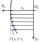
Figure 6 Function f( y T ) MathType@MTEF@5@5@+= feaagKart1ev2aqatCvAUfeBSjuyZL2yd9gzLbvyNv2CaerbuLwBLn hiov2DGi1BTfMBaeXatLxBI9gBaerbd9wDYLwzYbItLDharqqtubsr 4rNCHbGeaGqipu0Je9sqqrpepC0xbbL8F4rqqrFfpeea0xe9Lq=Jc9 vqaqpepm0xbba9pwe9Q8fs0=yqaqpepae9pg0FirpepeKkFr0xfr=x fr=xb9adbaqaaeGaciGaaiaabeqaamaabaabaaGcbaqcLbsacaWGMb GcdaqadaqaaKqzGeGaamyEaSWaaSbaaeaajugWaiaadsfaaSqabaaa kiaawIcacaGLPaaaaaa@3CB9@ expressing a rate of decrease in peripheral speed at position y T MathType@MTEF@5@5@+= feaagKart1ev2aqatCvAUfeBSjuyZL2yd9gzLbvyNv2CaerbuLwBLn hiov2DGi1BTfMBaeXatLxBI9gBaerbd9wDYLwzYbItLDharqqtubsr 4rNCHbGeaGqipu0Je9sqqrpepC0xbbL8F4rqqrFfpeea0xe9Lq=Jc9 vqaqpepm0xbba9pwe9Q8fs0=yqaqpepae9pg0FirpepeKkFr0xfr=x fr=xb9adbaqaaeGaciGaaiaabeqaamaabaabaaGcbaqcLbsacaWG5b WcdaWgaaqaaKqzadGaamivaaWcbeaaaaa@39A2@ to that of the center position of the roller.

 When the crown roller has the shape as shown in Figure 7, function f( y T ) MathType@MTEF@5@5@+= feaagKart1ev2aaatCvAUfeBSjuyZL2yd9gzLbvyNv2CaerbuLwBLn hiov2DGi1BTfMBaeXatLxBI9gBaerbd9wDYLwzYbItLDharqqtubsr 4rNCHbGeaGqipu0Je9sqqrpepC0xbbL8F4rqqrFfpeea0xe9Lq=Jc9 vqaqpepm0xbba9pwe9Q8fs0=yqaqpepae9pg0FirpepeKkFr0xfr=x fr=xb9adbaqaaeGaciGaaiaabeqaamaabaabaaGcbaGaamOzaiaacI cacaWG5bWaaSbaaSqaaiaadsfaaeqaaOGaaiykaaaa@3A27@ is expressed as follows:

f( y T )= y T 2 2R r 0 MathType@MTEF@5@5@+= feaagKart1ev2aaatCvAUfeBSjuyZL2yd9gzLbvyNv2CaerbuLwBLn hiov2DGi1BTfMBaeXatLxBI9gBaerbd9wDYLwzYbItLDharqqtubsr 4rNCHbGeaGqipu0Je9sqqrpepC0xbbL8F4rqqrFfpeea0xe9Lq=Jc9 vqaqpepm0xbba9pwe9Q8fs0=yqaqpepae9pg0FirpepeKkFr0xfr=x fr=xb9adbaqaaeGaciGaaiaabeqaamaabaabaaGcbaGaamOzaiaacI cacaWG5bWaaSbaaSqaaiaadsfaaeqaaOGaaiykaiabg2da9maalaaa baGaamyEamaaDaaaleaacaWGubaabaGaaGOmaaaaaOqaaiaaikdaca WGsbGaamOCamaaBaaaleaacaaIWaaabeaaaaaaaa@4177@ ,          (2)

where R and r 0 MathType@MTEF@5@5@+= feaagKart1ev2aaatCvAUfeBSjuyZL2yd9gzLbvyNv2CaerbuLwBLn hiov2DGi1BTfMBaeXatLxBI9gBaerbd9wDYLwzYbItLDharqqtubsr 4rNCHbGeaGqipu0Je9sqqrpepC0xbbL8F4rqqrFfpeea0xe9Lq=Jc9 vqaqpepm0xbba9pwe9Q8fs0=yqaqpepae9pg0FirpepeKkFr0xfr=x fr=xb9adbaqaaeGaciGaaiaabeqaamaabaabaaGcbaGaamOCamaaBa aaleaacaaIWaaabeaaaaa@37B3@ are the radius of curvature and radius of the center of the crown roller, respectively.

Substituting Eq. (2) into Eq. (1), the tilt angle can be expressed as

  θ= 1 6R r 0 B { | ( y B + B 2 ) 3 || ( y B + B 2 ) 3 | } MathType@MTEF@5@5@+= feaagKart1ev2aaatCvAUfeBSjuyZL2yd9gzLbvyNv2CaerbuLwBLn hiov2DGi1BTfMBaeXatLxBI9gBaerbd9wDYLwzYbItLDharqqtubsr 4rNCHbGeaGqipu0Je9sqqrpepC0xbbL8F4rqqrFfpeea0xe9Lq=Jc9 vqaqpepm0xbba9pwe9Q8fs0=yqaqpepae9pg0FirpepeKkFr0xfr=x fr=xb9adbaqaaeGaciGaaiaabeqaamaabaabaaGcbaqcLbsacqaH4o qCkiabg2da9maalaaabaqcLbsacaaIXaaakeaajugibiaaiAdacaWG sbGaamOCaOWaaSbaaSqaaKqzadGaaGimaaWcbeaajugibiaadkeaaa GcdaGadaqaamaaemaabaWaaeWaaeaacaWG5bWaaSbaaSqaaiaadkea aeqaaKqzGeGaey4kaSIcdaWcaaqaaKqzGeGaamOqaaGcbaqcLbsaca aIYaaaaaGccaGLOaGaayzkaaWcdaahaaqabeaajugWaiaaiodaaaaa kiaawEa7caGLiWoajugibiabgkHiTOWaaqWaaeaadaqadaqaaiaadM hadaWgaaWcbaGaamOqaaqabaqcLbsacqGHRaWkkmaalaaabaqcLbsa caWGcbaakeaajugibiaaikdaaaaakiaawIcacaGLPaaalmaaCaaabe qaaKqzadGaaG4maaaaaOGaay5bSlaawIa7aaGaay5Eaiaaw2haaaaa @5EE8@  ,   ( y B 0) MathType@MTEF@5@5@+= feaagKart1ev2aaatCvAUfeBSjuyZL2yd9gzLbvyNv2CaerbuLwBLn hiov2DGi1BTfMBaeXatLxBI9gBaerbd9wDYLwzYbItLDharqqtubsr 4rNCHbGeaGqipu0Je9sqqrpepC0xbbL8F4rqqrFfpeea0xe9Lq=Jc9 vqaqpepm0xbba9pwe9Q8fs0=yqaqpepae9pg0FirpepeKkFr0xfr=x fr=xb9adbaqaaeGaciGaaiaabeqaamaabaabaaGcbaGaaiikaiaadM hadaWgaaWcbaGaamOqaaqabaqcLbsacqGHLjYScaaIWaGccaGGPaaa aa@3C39@        (3)

θ= 1 6R r 0 B { | ( y B + B 2 ) 3 || ( y B + B 2 ) 3 | } MathType@MTEF@5@5@+= feaagKart1ev2aaatCvAUfeBSjuyZL2yd9gzLbvyNv2CaerbuLwBLn hiov2DGi1BTfMBaeXatLxBI9gBaerbd9wDYLwzYbItLDharqqtubsr 4rNCHbGeaGqipu0Je9sqqrpepC0xbbL8F4rqqrFfpeea0xe9Lq=Jc9 vqaqpepm0xbba9pwe9Q8fs0=yqaqpepae9pg0FirpepeKkFr0xfr=x fr=xb9adbaqaaeGaciGaaiaabeqaamaabaabaaGcbaqcLbsacqaH4o qCkiabg2da9KqzGeGaeyOeI0IcdaWcaaqaaKqzGeGaaGymaaGcbaqc LbsacaaI2aGaamOuaiaadkhakmaaBaaaleaajugWaiaaicdaaSqaba qcLbsacaWGcbaaaOWaaiWaaeaadaabdaqaamaabmaabaGaamyEamaa BaaaleaacaWGcbaabeaajugibiabgUcaROWaaSaaaeaajugibiaadk eaaOqaaKqzGeGaaGOmaaaaaOGaayjkaiaawMcaaSWaaWbaaeqabaqc LbmacaaIZaaaaaGccaGLhWUaayjcSdGaeyOeI0YaaqWaaeaadaqada qaaiaadMhadaWgaaWcbaGaamOqaaqabaqcLbsacqGHRaWkkmaalaaa baqcLbsacaWGcbaakeaajugibiaaikdaaaaakiaawIcacaGLPaaalm aaCaaabeqaaKqzadGaaG4maaaaaOGaay5bSlaawIa7aaGaay5Eaiaa w2haaaaa@5FD5@    .    ( y B <0) MathType@MTEF@5@5@+= feaagKart1ev2aaatCvAUfeBSjuyZL2yd9gzLbvyNv2CaerbuLwBLn hiov2DGi1BTfMBaeXatLxBI9gBaerbd9wDYLwzYbItLDharqqtubsr 4rNCHbGeaGqipu0Je9sqqrpepC0xbbL8F4rqqrFfpeea0xe9Lq=Jc9 vqaqpepm0xbba9pwe9Q8fs0=yqaqpepae9pg0FirpepeKkFr0xfr=x fr=xb9adbaqaaeGaciGaaiaabeqaamaabaabaaGcbaGaaiikaiaadM hadaWgaaWcbaGaamOqaaqabaqcLbsacqGH8aapcaaIWaGccaGGPaaa aa@3B77@        (4)

Figure 7 Geometric parameters of crown roller.

Calculation of lateral belt motion

The lateral belt position on the downstream roller was calculated using the angle between the rotation direction of the roller and the belt centerline (hereinafter referred to as the approach angle) and the transportation distance of the belt. The lateral belt position on the downstream roller on the tight and slack sides at calculation step i can be calculated using Eqs. (5) and (6), respectively, referring to Figure 8.

Figure 8 Calculation of belt position in y T MathType@MTEF@5@5@+= feaagKart1ev2aaatCvAUfeBSjuyZL2yd9gzLbvyNv2CaerbuLwBLn hiov2DGi1BTfMBaeXatLxBI9gBaerbd9wDYLwzYbItLDharqqtubsr 4rNCHbGeaGqipu0Je9sqqrpepC0xbbL8F4rqqrFfpeea0xe9Lq=Jc9 vqaqpepm0xbba9pwe9Q8fs0=yqaqpepae9pg0FirpepeKkFr0xfr=x fr=xb9adbaqaaeGaciGaaiaabeqaamaabaabaaGcbaqcLbsacaWG5b GcdaWgaaWcbaqcLbmacaWGubaaleqaaaaa@39AB@ and y S MathType@MTEF@5@5@+= feaagKart1ev2aaatCvAUfeBSjuyZL2yd9gzLbvyNv2CaerbuLwBLn hiov2DGi1BTfMBaeXatLxBI9gBaerbd9wDYLwzYbItLDharqqtubsr 4rNCHbGeaGqipu0Je9sqqrpepC0xbbL8F4rqqrFfpeea0xe9Lq=Jc9 vqaqpepm0xbba9pwe9Q8fs0=yqaqpepae9pg0FirpepeKkFr0xfr=x fr=xb9adbaqaaeGaciGaaiaabeqaamaabaabaaGcbaqcLbsacaWG5b WcdaWgaaqaaKqzadGaam4uaaWcbeaaaaa@39A0@ directions on crown and cylindrical rollers.

y Ti = y Ti1 + ϕ Ti Δ x T MathType@MTEF@5@5@+= feaagKart1ev2aaatCvAUfeBSjuyZL2yd9gzLbvyNv2CaerbuLwBLn hiov2DGi1BTfMBaeXatLxBI9gBaerbd9wDYLwzYbItLDharqqtubsr 4rNCHbGeaGqipu0Je9sqqrpepC0xbbL8F4rqqrFfpeea0xe9Lq=Jc9 vqaqpepm0xbba9pwe9Q8fs0=yqaqpepae9pg0FirpepeKkFr0xfr=x fr=xb9adbaqaaeGaciGaaiaabeqaamaabaabaaGcbaqcLbsacaWG5b WcdaWgaaqaaKqzadGaamivaiaadMgaaSqabaGccqGH9aqpjugibiaa dMhalmaaBaaabaqcLbmacaWGubGaamyAaiabgkHiTiaaigdaaSqaba GccqGHRaWkjugibiabew9aMTWaaSbaaeaajugWaiaadsfacaWGPbaa leqaaKqzGeGaeyyXICTaeuiLdqKaamiEaSWaaSbaaeaajugWaiaads faaSqabaaaaa@4FE9@ ,          (5)

y Si = y Si1 + ϕ Si Δ x S MathType@MTEF@5@5@+= feaagKart1ev2aaatCvAUfeBSjuyZL2yd9gzLbvyNv2CaerbuLwBLn hiov2DGi1BTfMBaeXatLxBI9gBaerbd9wDYLwzYbItLDharqqtubsr 4rNCHbGeaGqipu0Je9sqqrpepC0xbbL8F4rqqrFfpeea0xe9Lq=Jc9 vqaqpepm0xbba9pwe9Q8fs0=yqaqpepae9pg0FirpepeKkFr0xfr=x fr=xb9adbaqaaeGaciGaaiaabeqaamaabaabaaGcbaqcLbsacaWG5b GcdaWgaaWcbaGaam4uaiaadMgaaeqaaOGaeyypa0JaamyEamaaBaaa leaacaWGtbGaamyAaiabgkHiTiaaigdaaeqaaOGaey4kaSIaeqy1dy 2aaSbaaSqaaKqzadGaam4uaiaadMgaaSqabaqcLbsacqGHflY1cqqH uoarcaWG4bGcdaWgaaWcbaqcLbmacaWGtbaaleqaaaaa@4C69@ ,          (6)

where y Ti MathType@MTEF@5@5@+= feaagKart1ev2aaatCvAUfeBSjuyZL2yd9gzLbvyNv2CaerbuLwBLn hiov2DGi1BTfMBaeXatLxBI9gBaerbd9wDYLwzYbItLDharqqtubsr 4rNCHbGeaGqipu0Je9sqqrpepC0xbbL8F4rqqrFfpeea0xe9Lq=Jc9 vqaqpepm0xbba9pwe9Q8fs0=yqaqpepae9pg0FirpepeKkFr0xfr=x fr=xb9adbaqaaeGaciGaaiaabeqaamaabaabaaGcbaqcLbsacaWG5b WcdaWgaaqaaKqzadGaamivaiaadMgaaSqabaaaaa@3A8F@ and y Si MathType@MTEF@5@5@+= feaagKart1ev2aaatCvAUfeBSjuyZL2yd9gzLbvyNv2CaerbuLwBLn hiov2DGi1BTfMBaeXatLxBI9gBaerbd9wDYLwzYbItLDharqqtubsr 4rNCHbGeaGqipu0Je9sqqrpepC0xbbL8F4rqqrFfpeea0xe9Lq=Jc9 vqaqpepm0xbba9pwe9Q8fs0=yqaqpepae9pg0FirpepeKkFr0xfr=x fr=xb9adbaqaaeGaciGaaiaabeqaamaabaabaaGcbaqcLbsacaWG5b GcdaWgaaWcbaGaam4uaiaadMgaaeqaaaaa@395F@ are the lateral belt positions of the belt centerline at the crown roller on the tight side and the cylindrical roller on the slack side, respectively, in the lateral direction at calculation step i MathType@MTEF@5@5@+= feaagKart1ev2aaatCvAUfeBSjuyZL2yd9gzLbvyNv2CaerbuLwBLn hiov2DGi1BTfMBaeXatLxBI9gBaerbd9wDYLwzYbItLDharqqtubsr 4rNCHbGeaGqipu0Je9sqqrpepC0xbbL8F4rqqrFfpeea0xe9Lq=Jc9 vqaqpepm0xbba9pwe9Q8fs0=yqaqpepae9pg0FirpepeKkFr0xfr=x fr=xb9adbaqaaeGaciGaaiaabeqaamaabaabaaGcbaGaamyAaaaa@36C4@ . ϕ Ti MathType@MTEF@5@5@+= feaagKart1ev2aaatCvAUfeBSjuyZL2yd9gzLbvyNv2CaerbuLwBLn hiov2DGi1BTfMBaeXatLxBI9gBaerbd9wDYLwzYbItLDharqqtubsr 4rNCHbGeaGqipu0Je9sqqrpepC0xbbL8F4rqqrFfpeea0xe9Lq=Jc9 vqaqpepm0xbba9pwe9Q8fs0=yqaqpepae9pg0FirpepeKkFr0xfr=x fr=xb9adbaqaaeGaciGaaiaabeqaamaabaabaaGcbaqcLbsacqaHvp GzlmaaBaaabaqcLbmacaWGubGaamyAaaWcbeaaaaa@3B59@ and ϕ Si MathType@MTEF@5@5@+= feaagKart1ev2aaatCvAUfeBSjuyZL2yd9gzLbvyNv2CaerbuLwBLn hiov2DGi1BTfMBaeXatLxBI9gBaerbd9wDYLwzYbItLDharqqtubsr 4rNCHbGeaGqipu0Je9sqqrpepC0xbbL8F4rqqrFfpeea0xe9Lq=Jc9 vqaqpepm0xbba9pwe9Q8fs0=yqaqpepae9pg0FirpepeKkFr0xfr=x fr=xb9adbaqaaeGaciGaaiaabeqaamaabaabaaGcbaGaeqy1dy2aaS baaSqaaKqzadGaam4uaiaadMgaaSqabaaaaa@3AC9@ are the approach angles on the tight and slack sides, respectively, Δ x T MathType@MTEF@5@5@+= feaagKart1ev2aaatCvAUfeBSjuyZL2yd9gzLbvyNv2CaerbuLwBLn hiov2DGi1BTfMBaeXatLxBI9gBaerbd9wDYLwzYbItLDharqqtubsr 4rNCHbGeaGqipu0Je9sqqrpepC0xbbL8F4rqqrFfpeea0xe9Lq=Jc9 vqaqpepm0xbba9pwe9Q8fs0=yqaqpepae9pg0FirpepeKkFr0xfr=x fr=xb9adbaqaaeGaciGaaiaabeqaamaabaabaaGcbaqcLbsacqqHuo arcaWG4bWcdaWgaaqaaKqzadGaamivaaWcbeaaaaa@3B06@ and Δ x S MathType@MTEF@5@5@+= feaagKart1ev2aaatCvAUfeBSjuyZL2yd9gzLbvyNv2CaerbuLwBLn hiov2DGi1BTfMBaeXatLxBI9gBaerbd9wDYLwzYbItLDharqqtubsr 4rNCHbGeaGqipu0Je9sqqrpepC0xbbL8F4rqqrFfpeea0xe9Lq=Jc9 vqaqpepm0xbba9pwe9Q8fs0=yqaqpepae9pg0FirpepeKkFr0xfr=x fr=xb9adbaqaaeGaciGaaiaabeqaamaabaabaaGcbaqcLbsacqqHuo arcaWG4bGcdaWgaaWcbaqcLbmacaWGtbaaleqaaaaa@3B0F@ are the belt transportation distances at each calculation step.

On the tight side, the approach angle is influenced not only by the crown roller, but also by the shear deformation of the belt. Figure 9 shows the belt approaching the crown roller. From Figure 9, the shear force, Q MathType@MTEF@5@5@+= feaagKart1ev2aaatCvAUfeBSjuyZL2yd9gzLbvyNv2CaerbuLwBLn hiov2DGi1BTfMBaeXatLxBI9gBaerbd9wDYLwzYbItLDharqqtubsr 4rNCHbGeaGqipu0Je9sqqrpepC0xbbL8F4rqqrFfpeea0xe9Lq=Jc9 vqaqpepm0xbba9pwe9Q8fs0=yqaqpepae9pg0FirpepeKkFr0xfr=x fr=xb9adbaqaaeGaciGaaiaabeqaamaabaabaaGcbaGaamyuaaaa@36AC@ ,   acting on the cross-sectional area of the belt can be expressed as follows:

Figure 9 Shear force acting on cross-sectional area of belt near crown roller.

Q=GAγ=AEεsin(θ+ψ) MathType@MTEF@5@5@+= feaagKart1ev2aaatCvAUfeBSjuyZL2yd9gzLbvyNv2CaerbuLwBLn hiov2DGi1BTfMBaeXatLxBI9gBaerbd9wDYLwzYbItLDharqqtubsr 4rNCHbGeaGqipu0Je9sqqrpepC0xbbL8F4rqqrFfpeea0xe9Lq=Jc9 vqaqpepm0xbba9pwe9Q8fs0=yqaqpepae9pg0FirpepeKkFr0xfr=x fr=xb9adbaqaaeGaciGaaiaabeqaamaabaabaaGcbaqcLbsacaWGrb Gaeyypa0Jaam4raiaadgeacqaHZoWzcqGH9aqpcaWGbbGaamyraiab ew7aLjGacohacaGGPbGaaiOBaiaacIcacqaH4oqCcqGHRaWkcqaHip qEcaGGPaaaaa@484E@ ,          (7)

where G is the transverse elasticity modulus of the belt and A is the cross-sectional area of the belt. E is Young’s modulus of the belt, ε MathType@MTEF@5@5@+= feaagKart1ev2aaatCvAUfeBSjuyZL2yd9gzLbvyNv2CaerbuLwBLn hiov2DGi1BTfMBaeXatLxBI9gBaerbd9wDYLwzYbItLDharqqtubsr 4rNCHbGeaGqipu0Je9sqqrpepC0xbbL8F4rqqrFfpeea0xe9Lq=Jc9 vqaqpepm0xbba9pwe9Q8fs0=yqaqpepae9pg0FirpepeKkFr0xfr=x fr=xb9adbaqaaeGaciGaaiaabeqaamaabaabaaGcbaqcLbsacqaH1o qzaaa@380C@ is the strain due to the belt tension, and ψ MathType@MTEF@5@5@+= feaagKart1ev2aaatCvAUfeBSjuyZL2yd9gzLbvyNv2CaerbuLwBLn hiov2DGi1BTfMBaeXatLxBI9gBaerbd9wDYLwzYbItLDharqqtubsr 4rNCHbGeaGqipu0Je9sqqrpepC0xbbL8F4rqqrFfpeea0xe9Lq=Jc9 vqaqpepm0xbba9pwe9Q8fs0=yqaqpepae9pg0FirpepeKkFr0xfr=x fr=xb9adbaqaaeGaciGaaiaabeqaamaabaabaaGcbaqcLbsacqaHip qEaaa@3833@ is the angle due to the relative belt position between the crown and cylindrical rollers expressed as follows:

ψ= y Tu y Td L MathType@MTEF@5@5@+= feaagKart1ev2aaatCvAUfeBSjuyZL2yd9gzLbvyNv2CaerbuLwBLn hiov2DGi1BTfMBaeXatLxBI9gBaerbd9wDYLwzYbItLDharqqtubsr 4rNCHbGeaGqipu0Je9sqqrpepC0xbbL8F4rqqrFfpeea0xe9Lq=Jc9 vqaqpepm0xbba9pwe9Q8fs0=yqaqpepae9pg0FirpepeKkFr0xfr=x fr=xb9adbaqaaeGaciGaaiaabeqaamaabaabaaGcbaqcLbsacqaHip qEcqGH9aqpkmaalaaabaqcLbsacaWG5bGcdaWgaaWcbaqcLbmacaWG ubGaamyDaKqzGeGaeyOeI0caleqaaKqzGeGaamyEaSWaaSbaaeaaju gWaiaadsfacaWGKbaaleqaaaGcbaqcLbsacaWGmbaaaaaa@45BC@ ,         (8)

where y Tu MathType@MTEF@5@5@+= feaagKart1ev2aaatCvAUfeBSjuyZL2yd9gzLbvyNv2CaerbuLwBLn hiov2DGi1BTfMBaeXatLxBI9gBaerbd9wDYLwzYbItLDharqqtubsr 4rNCHbGeaGqipu0Je9sqqrpepC0xbbL8F4rqqrFfpeea0xe9Lq=Jc9 vqaqpepm0xbba9pwe9Q8fs0=yqaqpepae9pg0FirpepeKkFr0xfr=x fr=xb9adbaqaaeGaciGaaiaabeqaamaabaabaaGcbaqcLbsacaWG5b GcdaWgaaWcbaqcLbmacaWGubGaamyDaaWcbeaaaaa@3AA5@ is the belt position on the cylindrical roller, y Td MathType@MTEF@5@5@+= feaagKart1ev2aaatCvAUfeBSjuyZL2yd9gzLbvyNv2CaerbuLwBLn hiov2DGi1BTfMBaeXatLxBI9gBaerbd9wDYLwzYbItLDharqqtubsr 4rNCHbGeaGqipu0Je9sqqrpepC0xbbL8F4rqqrFfpeea0xe9Lq=Jc9 vqaqpepm0xbba9pwe9Q8fs0=yqaqpepae9pg0FirpepeKkFr0xfr=x fr=xb9adbaqaaeGaciGaaiaabeqaamaabaabaaGcbaqcLbsacaWG5b WcdaWgaaqaaKqzadGaamivaiaadsgaaSqabaaaaa@3A8A@ represents the belt position on the crown roller, and Lrepresents the distance between the upstream and downstream roller axes. The relationship between Young’s modulus and transverse elasticity is expressed as follows:

G= E 2( 1+ν ) MathType@MTEF@5@5@+= feaagKart1ev2aaatCvAUfeBSjuyZL2yd9gzLbvyNv2CaerbuLwBLn hiov2DGi1BTfMBaeXatLxBI9gBaerbd9wDYLwzYbItLDharqqtubsr 4rNCHbGeaGqipu0Je9sqqrpepC0xbbL8F4rqqrFfpeea0xe9Lq=Jc9 vqaqpepm0xbba9pwe9Q8fs0=yqaqpepae9pg0FirpepeKkFr0xfr=x fr=xb9adbaqaaeGaciGaaiaabeqaamaabaabaaGcbaqcLbsacaWGhb Gaeyypa0JcdaWcaaqaaKqzGeGaamyraaGcbaqcLbsacaaIYaGcdaqa daqaaKqzGeGaaGymaiabgUcaRiabe27aUbGccaGLOaGaayzkaaaaaa aa@4080@ ,         (9)

where, v is Poisson’s ration of the belt. Therefore, the shear angle of the belt at calculation step i can be obtained as follows:

γ i =2ε( 1+ν )sin( θ i + ψ i ) MathType@MTEF@5@5@+= feaagKart1ev2aaatCvAUfeBSjuyZL2yd9gzLbvyNv2CaerbuLwBLn hiov2DGi1BTfMBaeXatLxBI9gBaerbd9wDYLwzYbItLDharqqtubsr 4rNCHbGeaGqipu0Je9sqqrpepC0xbbL8F4rqqrFfpeea0xe9Lq=Jc9 vqaqpepm0xbba9pwe9Q8fs0=yqaqpepae9pg0FirpepeKkFr0xfr=x fr=xb9adbaqaaeGaciGaaiaabeqaamaabaabaaGcbaqcLbsacqaHZo WzlmaaBaaabaqcLbmacaWGPbaaleqaaKqzGeGaeyypa0JaaGOmaiab ew7aLPWaaeWaaeaajugibiaaigdacqGHRaWkcqaH9oGBaOGaayjkai aawMcaaKqzGeGaci4CaiaacMgacaGGUbGcdaqadaqaaKqzGeGaeqiU deNcdaWgaaWcbaqcLbmacaWGPbaaleqaaKqzGeGaey4kaSIaeqiYdK 3cdaWgaaqaaKqzadGaamyAaaWcbeaaaOGaayjkaiaawMcaaaaa@5310@ .          (10)

Therefore, the approach angle of the belt on the tight side is expressed as follows:

ϕ Ti = θ i + γ i MathType@MTEF@5@5@+= feaagKart1ev2aaatCvAUfeBSjuyZL2yd9gzLbvyNv2CaerbuLwBLn hiov2DGi1BTfMBaeXatLxBI9gBaerbd9wDYLwzYbItLDharqqtubsr 4rNCHbGeaGqipu0Je9sqqrpepC0xbbL8F4rqqrFfpeea0xe9Lq=Jc9 vqaqpepm0xbba9pwe9Q8fs0=yqaqpepae9pg0FirpepeKkFr0xfr=x fr=xb9adbaqaaeGaciGaaiaabeqaamaabaabaaGcbaqcLbsacqaHvp GzlmaaBaaabaqcLbmacaWGubGaamyAaaWcbeaajugibiabg2da9iab eI7aXTWaaSbaaeaajugWaiaadMgaaSqabaqcLbsacqGHRaWkcqaHZo WzlmaaBaaabaqcLbmacaWGPbaaleqaaaaa@4662@ .          (11)

On the slack side, the approach angle of the belt is the angle due to the relative belt positions on the upstream and downstream rollers, because the downstream roller is cylindrical, as shown in our previous study. Therefore, the approach angle of the belt at calculation step i is calculated as follows:

ϕ Si = y Sui y Sdi L MathType@MTEF@5@5@+= feaagKart1ev2aaatCvAUfeBSjuyZL2yd9gzLbvyNv2CaerbuLwBLn hiov2DGi1BTfMBaeXatLxBI9gBaerbd9wDYLwzYbItLDharqqtubsr 4rNCHbGeaGqipu0Je9sqqrpepC0xbbL8F4rqqrFfpeea0xe9Lq=Jc9 vqaqpepm0xbba9pwe9Q8fs0=yqaqpepae9pg0FirpepeKkFr0xfr=x fr=xb9adbaqaaeGaciGaaiaabeqaamaabaabaaGcbaqcLbsacqaHvp GzlmaaBaaabaqcLbmacaWGtbGaamyAaaWcbeaajugibiabg2da9OWa aSaaaeaajugibiaadMhakmaaBaaaleaajugWaiaadofacaWG1bGaam yAaaWcbeaajugibiabgkHiTiaadMhalmaaBaaabaqcLbmacaWGtbGa amizaiaadMgaaSqabaaakeaajugibiaadYeaaaaaaa@4ABB@ ,          (12)

where y Sui MathType@MTEF@5@5@+= feaagKart1ev2aaatCvAUfeBSjuyZL2yd9gzLbvyNv2CaerbuLwBLn hiov2DGi1BTfMBaeXatLxBI9gBaerbd9wDYLwzYbItLDharqqtubsr 4rNCHbGeaGqipu0Je9sqqrpepC0xbbL8F4rqqrFfpeea0xe9Lq=Jc9 vqaqpepm0xbba9pwe9Q8fs0=yqaqpepae9pg0FirpepeKkFr0xfr=x fr=xb9adbaqaaeGaciGaaiaabeqaamaabaabaaGcbaqcLbsacaWG5b GcdaWgaaWcbaqcLbmacaWGtbGaamyDaiaadMgaaSqabaaaaa@3B92@ and y Sdi MathType@MTEF@5@5@+= feaagKart1ev2aaatCvAUfeBSjuyZL2yd9gzLbvyNv2CaerbuLwBLn hiov2DGi1BTfMBaeXatLxBI9gBaerbd9wDYLwzYbItLDharqqtubsr 4rNCHbGeaGqipu0Je9sqqrpepC0xbbL8F4rqqrFfpeea0xe9Lq=Jc9 vqaqpepm0xbba9pwe9Q8fs0=yqaqpepae9pg0FirpepeKkFr0xfr=x fr=xb9adbaqaaeGaciGaaiaabeqaamaabaabaaGcbaqcLbsacaWG5b WcdaWgaaqaaKqzadGaam4uaiaadsgacaWGPbaaleqaaaaa@3B77@ are the belt positions on the crown and cylindrical rollers, respectively, on the slack side at calculation step i. When the calculation step is a rotation of the roller by 1°, the belt positions on the upstream roller on the tight and slack sides in calculation step i are expressed by Eqs. (13) and (14), respectively, assuming that the belt position on the roller does not change.

y Tui = y Sdi180 MathType@MTEF@5@5@+= feaagKart1ev2aaatCvAUfeBSjuyZL2yd9gzLbvyNv2CaerbuLwBLn hiov2DGi1BTfMBaeXatLxBI9gBaerbd9wDYLwzYbItLDharqqtubsr 4rNCHbGeaGqipu0Je9sqqrpepC0xbbL8F4rqqrFfpeea0xe9Lq=Jc9 vqaqpepm0xbba9pwe9Q8fs0=yqaqpepae9pg0FirpepeKkFr0xfr=x fr=xb9adbaqaaeGaciGaaiaabeqaamaabaabaaGcbaqcLbsacaWG5b WcdaWgaaqaaKqzadGaamivaiaadwhacaWGPbaaleqaaKqzGeGaeyyp a0JaamyEaSWaaSbaaeaajugWaiaadofacaWGKbGaamyAaiabgkHiTi aaigdacaaI4aGaaGimaaWcbeaaaaa@4554@ .         (13)

y Sui = y Tdi180 MathType@MTEF@5@5@+= feaagKart1ev2aaatCvAUfeBSjuyZL2yd9gzLbvyNv2CaerbuLwBLn hiov2DGi1BTfMBaeXatLxBI9gBaerbd9wDYLwzYbItLDharqqtubsr 4rNCHbGeaGqipu0Je9sqqrpepC0xbbL8F4rqqrFfpeea0xe9Lq=Jc9 vqaqpepm0xbba9pwe9Q8fs0=yqaqpepae9pg0FirpepeKkFr0xfr=x fr=xb9adbaqaaeGaciGaaiaabeqaamaabaabaaGcbaqcLbsacaWG5b WcdaWgaaqaaKqzadGaam4uaiaadwhacaWGPbaaleqaaKqzGeGaeyyp a0JaamyEaSWaaSbaaeaajugWaiaadsfacaWGKbGaamyAaiabgkHiTi aaigdacaaI4aGaaGimaaWcbeaaaaa@4554@ .          (14)

Experimental apparatus

Figure 10 shows the experimental apparatus used in this study, which comprises a two-roller belt system. As previously mentioned, the crown and cylindrical rollers were the driving and driven rollers, respectively. The crown roller was driven by a stepping motor. The distance between the axes of the crown and cylindrical rollers was 250 mm. In this study, the crown roller had a maximum diameter of 50 mm, length of 40 mm, and radii of curvature of 50, 70, and 100 mm. The cylindrical roller had a diameter of 50 mm and length of 40 mm.

Figure 10 Experimental apparatus used in this study.

The belt used in this experiment was a rubber flat endless belt with a thickness of 0.8 mm, width of 10 mm, and Young’s modulus of 12.5 MPa. The belt tension was set to approximately 4.5 N, and the corresponding strain was 0.043. Furthermore, a digital camera was mounted on a frame above the belt system to capture image data and obtain the belt position.

Measurement method

Positions A and B in Figure 10 indicate the measurement positions of the lateral belt motion on the downstream and upstream rollers used in this study. The belt began to contact the crown roller at position A and departed from the cylindrical roller at position B. In this study, the belt position was defined as the position of the belt centerline. The initial belt position on the crown and cylindrical rollers were set to 15 mm each.

The belt positions were obtained by processing the image data captured by the digital camera. Figure 11 shows the belt position measurement process. First, the image data are processed in MATLAB, trimmed, and binarized. Next, the number of pixels on the front and back sides of the belt at positions A and B are counted with respect to the belt position at position A when the belt is first set. The position of each point in the y-direction is then calculated by considering the resolution per pixel. The belt positions at the drive and driven rollers are calculated using Eqs. (15) and (16), respectively.

Figure 11 Measurement of belt position by processing image data captured by digital camera.

y Tdi = y Tdfi y Tdbi 2 MathType@MTEF@5@5@+= feaagKart1ev2aaatCvAUfeBSjuyZL2yd9gzLbvyNv2CaerbuLwBLn hiov2DGi1BTfMBaeXatLxBI9gBaerbd9wDYLwzYbItLDharqqtubsr 4rNCHbGeaGqipu0Je9sqqrpepC0xbbL8F4rqqrFfpeea0xe9Lq=Jc9 vqaqpepm0xbba9pwe9Q8fs0=yqaqpepae9pg0FirpepeKkFr0xfr=x fr=xb9adbaqaaeGaciGaaiaabeqaamaabaabaaGcbaqcLbsacaWG5b WcdaWgaaqaaKqzadGaamivaiaadsgacaWGPbaaleqaaKqzGeGaeyyp a0JcdaWcaaqaaKqzGeGaamyEaSWaaSbaaeaajugWaiaadsfacaWGKb GaamOzaiaadMgaaSqabaqcLbsacqGHsislcaWG5bWcdaWgaaqaaKqz adGaamivaiaadsgacaWGIbGaamyAaaWcbeaaaOqaaKqzGeGaaGOmaa aaaaa@4C7F@ .          (15)

y Tui = y Tufi y Tubi 2 MathType@MTEF@5@5@+= feaagKart1ev2aaatCvAUfeBSjuyZL2yd9gzLbvyNv2CaerbuLwBLn hiov2DGi1BTfMBaeXatLxBI9gBaerbd9wDYLwzYbItLDharqqtubsr 4rNCHbGeaGqipu0Je9sqqrpepC0xbbL8F4rqqrFfpeea0xe9Lq=Jc9 vqaqpepm0xbba9pwe9Q8fs0=yqaqpepae9pg0FirpepeKkFr0xfr=x fr=xb9adbaqaaeGaciGaaiaabeqaamaabaabaaGcbaqcLbsacaWG5b WcdaWgaaqaaKqzadGaamivaiaadwhacaWGPbaaleqaaKqzGeGaeyyp a0JcdaWcaaqaaKqzGeGaamyEaSWaaSbaaeaajugWaiaadsfacaWG1b GaamOzaiaadMgaaSqabaqcLbsacqGHsislcaWG5bGcdaWgaaWcbaqc LbmacaWGubGaamyDaiaadkgacaWGPbaaleqaaaGcbaqcLbsacaaIYa aaaaaa@4CBC@ .          (16)

The belt position is also measured using calipers when first setting the belt and after the belt is transported a predetermined distance in each experiment. The difference in the belt positions measured using these two methods is within 0.5 mm. The belt position is measured every two-fifths of roller rotation. The transport velocity of the belt is 78.5 mm/s.

Results

Figures 1214 show the experimental and calculated results for the belt position with radii of curvature of the crown roller (with a diameter of 50 mm) of 100, 70, and 50 mm and an initial belt set position of 15 mm. The experimental results are the average of the results of three experiments. The results from on the calculation method developed in this study for the belt position are in good agreement with the experimental results.
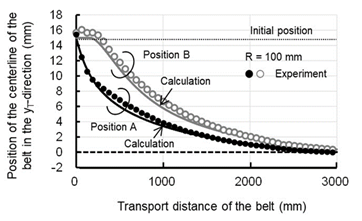
Figure 12 Comparison between experimental and calculation results of belt position in axial direction (Roller diameter: 50 mm, Radius of curvature: 100 mm).
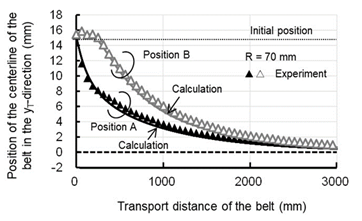
Figure 13 Comparison between experimental and calculation results of belt position in axial direction (Roller diameter: 50 mm, Radius of curvature: 70 mm).
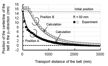
Figure 14 Comparison between experimental and calculation results of belt position in axial direction (Roller diameter: 50 mm, Radius of curvature: 50 mm).

The belt position on the crown roller (Point A) changes immediately after the roller rotates, whereas the belt position on the cylindrical roller (Point B) barely changes until the feed distance of the belt is approximately 250 mm. This validates that the mechanism of automatic alignment of the crown roller described previously.

Figure 15 shows the experimental and calculated results for the belt position on the crown roller with crown roller radius of curvature of 70 mm, a diameter of 30 and 50 mm, and an initial belt set position of 15 mm. The calculated results for the belt position for a diameter of 30 mm are also in relatively good agreement with the experimental results. Compared to the results for a diameter of 50 mm, the rate of change in the belt position for a diameter of 30 mm is greater than that for a diameter of 50 mm. Therefore, the analysis method for the lateral belt motion developed in this study is valid and the automatic alignment effect is expected to improve as the diameter of the crown roller decreases.
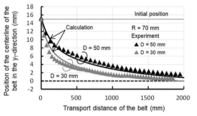
Figure 15 Experimental and calculated results of belt position on the crown roller for a diameter of 30 and 50 mm of crown roller.

The above results indicate that the analytical method developed in this study can predict the belt position and shift with considerable accuracy. From these results, it can be concluded that a major factor in automatic belt alignment is the inclination caused by the difference in the peripheral speed in the belt-width direction that occurs during belt wrapping around the crown roller. Specifically, the angle of inclination calculated from the difference in the peripheral speed in the belt width direction of the crown roller is the belt entry angle. The belt moves in the axial direction of the roller as it wraps around the roller at this angle of entry, which causes the automatic alignment of the belt.

Discussion

The results from the analytical method described above predict that belt tension affects the lateral belt motion. Although a previous study conducted by Yanabe showed that the effect of belt tension on belt alignment is extremely small, we considered it using the analytical method developed in this study.

Figure 16 shows the results of the belt position on the crown roller for belt strains of 0.02, 0.05, and 0.08. This figure shows that a smaller elongation strain of the belt, i.e., a smaller belt tension implies, a larger effect on the automatic belt alignment. The effect of the belt tension is large in the area where the difference in the belt position in the axial direction between the crown and cylindrical rollers is large. However, as the difference in the belt position in the axial direction decreases, the difference in the rate of change of the belt position decreases, and the automatic aligning effect does not significantly differ depending on the magnitude of the tension. Therefore, the belt tension has a slight effect on the time for the belt to move to the roller center position but does not have a significant effect on the automatic belt alignment.

Figure 16 Calculated results of belt position on crown roller for different belt tensions.

Conclusion

To ensure the reliability of the conveyance and power transmission mechanisms of belts, an analytical method that can clarify the relationship between the crown roller parameters  and the automatic alignment of the belt wrapped around the roller was investigated. The relationship between the crown roller geometry and belt alignment was examined. The results are summarized as folles.

  1. A calculation method was devised to predict the lateral belt motion on the crown roller. We assumed that the belt tilted owing to the difference in the peripheral speed of the crown roller in the axial direction and that the tilt angle at that time was the belt entry angle into the roller section. The lateral belt position calculated using this method agreed well with the experimental results.
  2. The good agreement between the calculation method and experimental results indicated that the lateral belt motion, which affected automatic belt alignment, was inversely proportional to the radius of curvature and the diameter of the crown
  3. Specifically, smaller radius of curvature and a smaller diameter of the crown roller were founded to be necessary to increase the effect on the automatic belt
  4. The belt tension showed a slight effect on the time for the the belt to move to the roller center position but did not have a significant effect on the automatic belt

Future issues include the evaluation of the automatic belt alignment of conical rollers, which has the same effect as crown rollers, and the examination of the automatic belt alignment of crown and conical rollers in a two-roller belt system with in-plane and out-of-plane misalignment angles.

Acknowledgments

None.

Conflicts of interest

Authors declare that there is no conflict of interest.

References

Creative Commons Attribution License

©2024 Yoshida, et al. This is an open access article distributed under the terms of the, which permits unrestricted use, distribution, and build upon your work non-commercially.