Submit manuscript...
eISSN: 2574-8092

International Robotics & Automation Journal

Research Article Volume 4 Issue 6

An innovative cutter spindle feed mode used for heavy-duty spiral bevel gear CNC machine tool

Yanwei XU,1,2 Aijun XU,1 Lihai CHEN,1 Menghui Chen,1,3 Xianfeng Li1,3

1School of Mechatronics Engineering, Henan University of Science and Technology, China
2Mechanized equipment advanced manufacturing collaborative innovation center of Henan Province, China
3Intelligent numerical control equipment engineering laboratory of Henan Province, China

Correspondence: Yanwei XU, School of Mechatronics Engineering, Henan University of Science and Technology, Luoyang, 471003, China

Received: November 14, 2017 | Published: December 20, 2018

Citation: Yanwei XU, Aijun XU, Lihai CHEN, et al. An innovative cutter spindle feed mode used for heavy-duty spiral bevel gear CNC machine tool. Int Rob Auto J. 2018;4(6):434-441. DOI: 10.15406/iratj.2018.04.00160

Download PDF

Abstract

In this study, in order to increase manufacture efficiency and improve machining precision of heavy-duty spiral bevel gear CNC (Computerized Numerical Control) machine tool, an innovative cutter spindle feed mode replacing the traditional work piece or spindle box feed mode used for heavy-duty spiral bevel gear CNC machine tool is proposed. The method is described as follows. Firstly, a three-dimensional structural model of heavy-duty spiral bevel gear CNC machine tool adopting the proposed cutter spindle feed mode is designed. Then, the numerical control machining model of heavy-duty spiral bevel gear CNC machine tool using the cutter spindle feed mode is constructed, including determining cutter location parameters, establishing machining coordinate system and calculating motion parameters. An example is consequently demonstrated to verify the established numerical control machining model. Finally, a virtual simulation model and an experimental model of heavy-duty spiral bevel gear CNC machine tool adopting the proposed cutter spindle feed mode are established and the validation of the proposed cutter spindle mode is conducted . Both the virtual simulation and experimental results show that the proposed cutter spindle feed mode used for heavy-duty spiral bevel gear CNC machine tool is feasible and effective with improved machining efficiency and accuracy.

Keywords: cutter spindle feed mode, spiral bevel gear, heavy-duty, cnc machine tool, virtual simulation

Introduction

Due to the smoothly meshing characteristics, spiral bevel gear is still a hot topic of research and has been widely used to various kinds of intersecting or crossed-axes power transmissions in many industry fields, such as aerospace, armament, metallurgy and refineries.1-3 Over the past few decades, many researchers have studied spiral bevel gear and its machine tool, especially on optimization of machine tool settings and modification of tooth surface based on tooth contact analysis (TCA).

Optimization of machine tool settings can improve the machining accuracy and meshing characteristics of spiral bevel gears.4 Used an optimization approach to systematically define the optimal head-cutter geometry and machine tool settings to minimize the tooth contact pressure and the transmission error simultaneously, by which the sensitivity of face-hobbed spiral bevel gears to the misalignments can be reduced.5 The author investigated the combined influence of machine tool settings for pinion teeth finishing and misalignments of the mating members on load distribution and transmission errors in mismatched spiral bevel gears.6 Presented a method to determine the optimal machine tool settings for manufacturing modified hypoid gears based on improved load distribution and reduced transmission errors. Cao, et al.7 developed an approach to design the pinion machine tool settings for spiral bevel gears by controlling contact path and transmission errors.

Tooth contact pressure, area and pattern directly influence meshing characteristics of spiral bevel gears. To improve meshing performances, TCA has been frequently used to investigate the modification of tooth surface. Litvin, et al.8 Used a local synthesis of spiral bevel gears to provide improved conditions of meshing within the neighborhood of the mean contact point. Sobolewski &Marciniec9 described a tool for analyzing tooth contact and transmission errors of spiral bevel gear sets with tooth flanks represented as CAD free-form surfaces. Vimercati10 proposed a mathematical model for spiral bevel gear tooth surface representation by face-hobbing method based on TCA under light and heavy loads and stress analysis. Argyris, et al.11 adopted an integrated computerized method to perform the synthesis, analysis and stress analysis of enhanced spiral bevel gear drives by application of computerized methods of local synthesis and simulation of meshing and contact of gear tooth surfaces. Simon12 investigated the influence of misalignments and tooth errors on load distribution, stresses and transmission errors in mismatched spiral bevel gears with the method of loaded TCA. Fang et al.13 developed an accurate and convenient edge TCA method of spiral bevel gears to determine the contact points on tooth edges and resolved the tooth edge contact problem successfully. However, the above studies are mainly focused on traditional spiral bevel gear machine tool. Recently, more and more researchers turn to apply their methods to CNC (Computerized Numerical Control) machine tool due to its greater manufacturing precision, better transmission characteristics, and higher efficiency.

Simon14 developed an algorithm for execution of motions on CNC hypoid generating machine tool for the manufacture of spiral bevel gears. Deng et al.15 presented a machining method of face milling using a disk cutter with a concave end to solve some common problems of CNC-machined spiral bevel gears. Suh, et al.16 adopted a CNC milling machine controlled by the 3/4-axis control mode to manufacture spiral bevel gears and ascertained the validity and effectiveness of the method by experimental cuts. Shih and Fong17 proposed a flank-correction method obtained directly from a six-axis Cartesian-type CNC hypoid generator in which high-order correction can be easily achieved through direct control of the CNC axis motion, and validation of this method was demonstrated by a numerical study. Liu et al.18 applied an adaptive acceleration-deceleration control method to spiral bevel gear CNC machining and its effectiveness was verified through related experimental study. Fan19,20 adopted a generic model of tooth surface generation for spiral bevel and hypoid gears produced by face-milling and face-hobbing processes conducted on free-form CNC hypoid gear generators.

Studies on modification of tooth surface are also conducted on CNC machine tool,21 as it is a preferred method to improve meshing characteristics of spiral bevel gears. Shih22 proposed a novel ease-off flank modification methodology for spiral bevel and hypoid gears made by a modern Cartesian-type hypoid gear generator. Simon23,24 used a method for the determination of optimal tooth modifications of spiral bevel gears for CNC machine tool, based on improved load distribution and reduced maximum tooth contact pressure and transmission errors. Su and He25 employed an ease-off based modification method of spiral bevel gear tooth surface, and the CNC machine-tool setting parameters approaching the target surface can be obtained.

The up-to-date literatures on spiral bevel gear and its machine tool are focused on TCA, transmission error analysis, optimization of machine-tool settings and multi-axis CNC machine tool. However, little attention has been paid to design of gear CNC machine tools for heavy-duty spiral bevel gears, especially those with the diameter bigger than 1000 mm. Heavy-duty spiral bevel gear machine tool is a typical representative of heavy-duty complex manufacturing equipment, and its performance directly influences spiral bevel gear’s manufacturing efficiency, machining precision, movement accuracy and transmission efficiency. Improving the manufacturing efficiency and machining accuracy of heavy-duty spiral bevel gears is of great importance. However, the efficiency and precision of heavy-duty spiral bevel gear machine tools with traditional feed mode by work piece or spindle box moving is relatively poor because of the huge weight of work piece or spindle box.

This paper proposes an innovative cutter spindle feed mode used for heavy-duty spiral bevel gear CNC machine tools to solve the problem of low efficiency and accuracy of heavy-duty spiral bevel gear machine tools with the traditional work piece or spindle box feed approach. The rest of the paper is organized as follows. Section 2 describes the basic theory of machining principle of spiral bevel gears. In section 3, structural model of heavy-duty spiral bevel gear CNC machine tool are first established and consequently the numerical control machining model of heavy-duty spiral bevel CNC machine tool using the proposed feed mode is constructed, including determining cutter location parameters, establishing machining coordinate system and calculating motion parameters. And the numerical control machining model is verified by an illustrative computation example. In section 4, a virtual simulation model and an experimental model of heavy-duty spiral bevel gear CNC machine tool adopting the proposed spindle feed mode are established and the validation of the proposed feed mode is conducted . Finally, Conclusions are drawn in section 5.

Methodology

In this section, firstly, the basic theory of machining principle of spiral bevel gears is presented. And then the diagram of the proposed cutter spindle feed mode used for heavy-duty spiral bevel gear CNC machine tool is also illustrated.

Machining principle of spiral bevel gears

Spiral bevel gears are usually manufactured through generating method for face milling by means of the virtual crown gear principle as shown in Figure 1.19,20 The blade edges of the rotating cutter, whose axis is offset from the axis of the virtual crown gear and imagined to be fixed to the virtual crown gear, function as a tooth of the virtual crown gear. During the machining process of a spiral bevel gear, the virtual crown gear and the gear work piece mesh and rotate around their respective axes at a predetermined ratio of rotation; therefore, the cutter will gradually cut out a tooth groove in the gear work piece. After cutting a tooth groove, the virtual crown gear returns to its original position and the gear work piece rotates to the next indexing position to prepare to cut the next tooth groove. The above procedure repeats until all the teeth are generated. Machining process for spiral bevel gears is illustrated in Figure 2.

Figure 1 Schematic illustration of the generating principle of face milling of spiral bevel gear.

Figure 2 Machining process for spiral bevel gears.

Diagram of the proposed cutter spindle feed mode for heavy-duty spiral bevel gear CNC machine tool

The cutter spindle feed mode is proposed for heavy-duty spiral bevel gear CNC machine tool to overcome the low precision and accuracy of heavy-duty spiral bevel gear machine tool with traditional workpiece or spindle box feed mode. The diagram of the proposed cutter spindle feed mode for heavy-duty spiral bevel gear CNC machine tool is described and illustrated in Figure 3.

Figure 3 Diagram of the proposed feed mode for heavy-duty spiral bevel gear CNC machine tool.

The proposed cutter spindle feed mode for heavy-duty spiral bevel gear CNC machine tool

Structural model of heavy-duty spiral bevel gear CNC machine tool

Heavy-duty spiral bevel gear CNC machine tool has a similar structure, machining principle and movement pattern with traditional mechanical spiral bevel gear machine tool. For the traditional spiral bevel gear machine tool or CNC spiral bevel gear machine tool, feed amount and feed speed are accurately controlled by the movement of work piece box moving left and right with the bed saddle or the movement of slippery pedestal type spindle box moving back and forth with the machine column. Due to the heavy weight of work piece or spindle box, it is very difficult to precisely control the feed speed of heavy-duty spiral bevel gear machine tool, and the manufacture efficiency will become relatively low if the traditional feed amount and feed speed are used on the heavy-duty spiral bevel gear machine tool. Therefore, the cutter spindle feed mode is proposed and adopted to control the feed amount and feed speed in the heavy-duty spiral bevel gear machine tool. In this way, feed movement can be easily achieved through machine tool spindle’s rectilinear stretching motion, completely replacing the traditional work piece or spindle box feed approach, and the manufacture efficiency and accuracy can be greatly improved with this new feed mode. Three-dimensional structural mode of heavy-duty spiral bevel gear machine tool is shown in Figure 4. The basic machining process is illustrated in Figure 5 and is described as follows. After machining one tooth space, the machine tool spindle retracted, the cradle reverts to its original position, and the work piece rotates one dividing angle at the same time, then to machine next tooth space. After finishing one machine cycle, the feed amount is changed by the machine tool spindle’s rectilinear stretching motion, and moves to the next machining cycle. This process repeats until the whole work piece gear is finished.
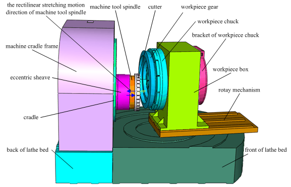
Figure 4 Structure of heavy duty spiral bevel gear machine tool.

Figure 5 The basic machining process of heavy-duty spiral bevel gear CNC machine tool.

Numerical control machining model of heavy-duty spiral bevel gear CNC machine tool

  1. Determining cutter location parameters
  2. Before the process of machining on spiral bevel gear with the principle of imaginary crown generating gear, the first step is to determine the cutter’s nominal radius r k MathType@MTEF@5@5@+= feaagKart1ev2aaatCvAUfeBSjuyZL2yd9gzLbvyNv2CaerbuLwBLn hiov2DGi1BTfMBaeXatLxBI9gBaerbd9wDYLwzYbItLDharqqtubsr 4rNCHbGeaGqipu0Je9sqqrpepC0xbbL8F4rqqrFfpeea0xe9Lq=Jc9 vqaqpepm0xbba9pwe9Q8fs0=yqaqpepae9pg0FirpepeKkFr0xfr=x fr=xb9adbaqaaeGaciGaaiaabeqaamaabaabaaGcbaqcfaOaaeOCam aaBaaabaGaae4Aaaqabaaaaa@3868@ through related calculation according to the geometric parameters of workpiece gear, and then to determine the cutter’s location parameters, which is the cutter’s center O k MathType@MTEF@5@5@+= feaagKart1ev2aaatCvAUfeBSjuyZL2yd9gzLbvyNv2CaerbuLwBLn hiov2DGi1BTfMBaeXatLxBI9gBaerbd9wDYLwzYbItLDharqqtubsr 4rNCHbGeaGqipu0Je9sqqrpepC0xbbL8F4rqqrFfpeea0xe9Lq=Jc9 vqaqpepm0xbba9pwe9Q8fs0=yqaqpepae9pg0FirpepeKkFr0xfr=x fr=xb9adbaqaaeGaciGaaiaabeqaamaabaabaaGcbaqcfaOaae4tam aaBaaabaGaae4Aaaqabaaaaa@3845@ in the machine coordinate systems. In this paper, the eccentric method is adopted to determine the cutter’s location parameters of the heavy-duty spiral bevel gear machine tool. The schematic diagram for calculation of the cutter’s location parameters is shown in Figure 6.
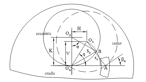
Figure 6 schematic diagrams of calculation the cutter’s location parameters.

    When adjusting the cutter location parameters of heavy-duty spiral bevel gear machine tool, the vertical coordinate V and horizontal coordinate H of the tool center O k MathType@MTEF@5@5@+= feaagKart1ev2aaatCvAUfeBSjuyZL2yd9gzLbvyNv2CaerbuLwBLn hiov2DGi1BTfMBaeXatLxBI9gBaerbd9wDYLwzYbItLDharqqtubsr 4rNCHbGeaGqipu0Je9sqqrpepC0xbbL8F4rqqrFfpeea0xe9Lq=Jc9 vqaqpepm0xbba9pwe9Q8fs0=yqaqpepae9pg0FirpepeKkFr0xfr=x fr=xb9adbaqaaeGaciGaaiaabeqaamaabaabaaGcbaqcfaOaae4tam aaBaaabaGaae4Aaaqabaaaaa@3845@ in the coordinate plane X m O m Y m MathType@MTEF@5@5@+= feaagKart1ev2aaatCvAUfeBSjuyZL2yd9gzLbvyNv2CaerbuLwBLn hiov2DGi1BTfMBaeXatLxBI9gBaerbd9wDYLwzYbItLDharqqtubsr 4rNCHbGeaGqipu0Je9sqqrpepC0xbbL8F4rqqrFfpeea0xe9Lq=Jc9 vqaqpepm0xbba9pwe9Q8fs0=yqaqpepae9pg0FirpepeKkFr0xfr=x fr=xb9adbaqaaeGaciGaaiaabeqaamaabaabaaGcbaqcfaOaaeiwam aaBaaabaGaaeyBaaqabaGaae4tamaaBaaabaGaaeyBaaqabaGaaeyw amaaBaaabaGaaeyBaaqabaaaaa@3C20@ are expressed as

    V= r k cos β m MathType@MTEF@5@5@+= feaagKart1ev2aaatCvAUfeBSjuyZL2yd9gzLbvyNv2CaerbuLwBLn hiov2DGi1BTfMBaeXatLxBI9gBaerbd9wDYLwzYbItLDharqqtubsr 4rNCHbGeaGqipu0Je9sqqrpepC0xbbL8F4rqqrFfpeea0xe9Lq=Jc9 vqaqpepm0xbba9pwe9Q8fs0=yqaqpepae9pg0FirpepeKkFr0xfr=x fr=xb9adbaqaaeGaciGaaiaabeqaamaabaabaaGcbaqcfaOaamOvai abg2da9iaadkhadaWgaaqcfawaaiaadUgaaKqbagqaaiabgwSixlGa cogacaGGVbGaai4Caiabek7aInaaBaaajuaybaGaamyBaaqcfayaba aaaa@4416@ (1)

    H= L m r k sin β m MathType@MTEF@5@5@+= feaagKart1ev2aaatCvAUfeBSjuyZL2yd9gzLbvyNv2CaerbuLwBLn hiov2DGi1BTfMBaeXatLxBI9gBaerbd9wDYLwzYbItLDharqqtubsr 4rNCHbGeaGqipu0Je9sqqrpepC0xbbL8F4rqqrFfpeea0xe9Lq=Jc9 vqaqpepm0xbba9pwe9Q8fs0=yqaqpepae9pg0FirpepeKkFr0xfr=x fr=xb9adbaqaaeGaciGaaiaabeqaamaabaabaaGcbaqcfaOaamisai abg2da9iaadYeadaWgaaqcfawaaiaad2gaaKqbagqaaiabgkHiTiaa dkhadaWgaaqcfawaaiaadUgaaeqaaKqbakGacohacaGGPbGaaiOBai abek7aInaaBaaajuaybaGaamyBaaqcfayabaaaaa@4590@ (2)

    Where β m MathType@MTEF@5@5@+= feaagKart1ev2aaatCvAUfeBSjuyZL2yd9gzLbvyNv2CaerbuLwBLn hiov2DGi1BTfMBaeXatLxBI9gBaerbd9wDYLwzYbItLDharqqtubsr 4rNCHbGeaGqipu0Je9sqqrpepC0xbbL8F4rqqrFfpeea0xe9Lq=Jc9 vqaqpepm0xbba9pwe9Q8fs0=yqaqpepae9pg0FirpepeKkFr0xfr=x fr=xb9adbaqaaeGaciGaaiaabeqaamaabaabaaGcbaqcfaOaaeOSdm aaBaaajuaybaGaaeyBaaqcfayabaaaaa@39A9@ is helical angle and L m MathType@MTEF@5@5@+= feaagKart1ev2aaatCvAUfeBSjuyZL2yd9gzLbvyNv2CaerbuLwBLn hiov2DGi1BTfMBaeXatLxBI9gBaerbd9wDYLwzYbItLDharqqtubsr 4rNCHbGeaGqipu0Je9sqqrpepC0xbbL8F4rqqrFfpeea0xe9Lq=Jc9 vqaqpepm0xbba9pwe9Q8fs0=yqaqpepae9pg0FirpepeKkFr0xfr=x fr=xb9adbaqaaeGaciGaaiaabeqaamaabaabaaGcbaqcfaOaaeitam aaBaaajuaybaGaamyBaaqabaaaaa@38B4@ refers to cone distance. Then, the radial cutter spacing S k MathType@MTEF@5@5@+= feaagKart1ev2aaatCvAUfeBSjuyZL2yd9gzLbvyNv2CaerbuLwBLn hiov2DGi1BTfMBaeXatLxBI9gBaerbd9wDYLwzYbItLDharqqtubsr 4rNCHbGeaGqipu0Je9sqqrpepC0xbbL8F4rqqrFfpeea0xe9Lq=Jc9 vqaqpepm0xbba9pwe9Q8fs0=yqaqpepae9pg0FirpepeKkFr0xfr=x fr=xb9adbaqaaeGaciGaaiaabeqaamaabaabaaGcbaqcfaOaae4uam aaBaaajuaybaGaae4Aaaqcfayabaaaaa@3945@ and the angular cutter spacingare described as

    S k = V 2 + H 2 MathType@MTEF@5@5@+= feaagKart1ev2aaatCvAUfeBSjuyZL2yd9gzLbvyNv2CaerbuLwBLn hiov2DGi1BTfMBaeXatLxBI9gBaerbd9wDYLwzYbItLDharqqtubsr 4rNCHbGeaGqipu0Je9sqqrpepC0xbbL8F4rqqrFfpeea0xe9Lq=Jc9 vqaqpepm0xbba9pwe9Q8fs0=yqaqpepae9pg0FirpepeKkFr0xfr=x fr=xb9adbaqaaeGaciGaaiaabeqaamaabaabaaGcbaqcfaOaam4uam aaBaaajuaybaGaam4AaaqabaqcfaOaeyypa0ZaaOaaaeaacaWGwbWa aWbaaKqbGfqabaGaaGOmaaaajuaGcqGHRaWkcaWGibWaaWbaaeqaju aybaGaaGOmaaaaaKqbagqaaaaa@409D@ (3)

    q=arctan V H MathType@MTEF@5@5@+= feaagKart1ev2aaatCvAUfeBSjuyZL2yd9gzLbvyNv2CaerbuLwBLn hiov2DGi1BTfMBaeXatLxBI9gBaerbd9wDYLwzYbItLDharqqtubsr 4rNCHbGeaGqipu0Je9sqqrpepC0xbbL8F4rqqrFfpeea0xe9Lq=Jc9 vqaqpepm0xbba9pwe9Q8fs0=yqaqpepae9pg0FirpepeKkFr0xfr=x fr=xb9adbaqaaeGaciGaaiaabeqaamaabaabaaGcbaqcfaOaamyCai abg2da9iGacggacaGGYbGaai4yaiaacshacaGGHbGaaiOBamaalaaa baGaamOvaaqaaiaadIeaaaaaaa@3FAB@ (4)

    Before adjusting the cutter location parameters, cutter’s center O k MathType@MTEF@5@5@+= feaagKart1ev2aaatCvAUfeBSjuyZL2yd9gzLbvyNv2CaerbuLwBLn hiov2DGi1BTfMBaeXatLxBI9gBaerbd9wDYLwzYbItLDharqqtubsr 4rNCHbGeaGqipu0Je9sqqrpepC0xbbL8F4rqqrFfpeea0xe9Lq=Jc9 vqaqpepm0xbba9pwe9Q8fs0=yqaqpepae9pg0FirpepeKkFr0xfr=x fr=xb9adbaqaaeGaciGaaiaabeqaamaabaabaaGcbaqcfaOaae4tam aaBaaajuaybaGaae4Aaaqcfayabaaaaa@3941@ coincides with the center of the machine too O m MathType@MTEF@5@5@+= feaagKart1ev2aaatCvAUfeBSjuyZL2yd9gzLbvyNv2CaerbuLwBLn hiov2DGi1BTfMBaeXatLxBI9gBaerbd9wDYLwzYbItLDharqqtubsr 4rNCHbGeaGqipu0Je9sqqrpepC0xbbL8F4rqqrFfpeea0xe9Lq=Jc9 vqaqpepm0xbba9pwe9Q8fs0=yqaqpepae9pg0FirpepeKkFr0xfr=x fr=xb9adbaqaaeGaciGaaiaabeqaamaabaabaaGcbaqcfaOaae4tam aaBaaajuaybaGaaeyBaaqabaaaaa@38B5@ . When adjusting the cutter location parameters, the eccentric rotates an angle φ MathType@MTEF@5@5@+= feaagKart1ev2aaatCvAUfeBSjuyZL2yd9gzLbvyNv2CaerbuLwBLn hiov2DGi1BTfMBaeXatLxBI9gBaerbd9wDYLwzYbItLDharqqtubsr 4rNCHbGeaGqipu0Je9sqqrpepC0xbbL8F4rqqrFfpeea0xe9Lq=Jc9 vqaqpepm0xbba9pwe9Q8fs0=yqaqpepae9pg0FirpepeKkFr0xfr=x fr=xb9adbaqaaeGaciGaaiaabeqaamaabaabaaGcbaqcfaOaaeOXda aa@37B0@ and drives the cutter’s center O k MathType@MTEF@5@5@+= feaagKart1ev2aaatCvAUfeBSjuyZL2yd9gzLbvyNv2CaerbuLwBLn hiov2DGi1BTfMBaeXatLxBI9gBaerbd9wDYLwzYbItLDharqqtubsr 4rNCHbGeaGqipu0Je9sqqrpepC0xbbL8F4rqqrFfpeea0xe9Lq=Jc9 vqaqpepm0xbba9pwe9Q8fs0=yqaqpepae9pg0FirpepeKkFr0xfr=x fr=xb9adbaqaaeGaciGaaiaabeqaamaabaabaaGcbaqcfaOaae4tam aaBaaajuaybaGaae4Aaaqcfayabaaaaa@3941@ to move from the machine tool center to O m MathType@MTEF@5@5@+= feaagKart1ev2aaatCvAUfeBSjuyZL2yd9gzLbvyNv2CaerbuLwBLn hiov2DGi1BTfMBaeXatLxBI9gBaerbd9wDYLwzYbItLDharqqtubsr 4rNCHbGeaGqipu0Je9sqqrpepC0xbbL8F4rqqrFfpeea0xe9Lq=Jc9 vqaqpepm0xbba9pwe9Q8fs0=yqaqpepae9pg0FirpepeKkFr0xfr=x fr=xb9adbaqaaeGaciGaaiaabeqaamaabaabaaGcbaqcfaOaae4tam aaBaaajuaybaGaaeyBaaqabaaaaa@38B5@ point B (shown in Figure 6) so that the distance between the cutter center O k MathType@MTEF@5@5@+= feaagKart1ev2aaatCvAUfeBSjuyZL2yd9gzLbvyNv2CaerbuLwBLn hiov2DGi1BTfMBaeXatLxBI9gBaerbd9wDYLwzYbItLDharqqtubsr 4rNCHbGeaGqipu0Je9sqqrpepC0xbbL8F4rqqrFfpeea0xe9Lq=Jc9 vqaqpepm0xbba9pwe9Q8fs0=yqaqpepae9pg0FirpepeKkFr0xfr=x fr=xb9adbaqaaeGaciGaaiaabeqaamaabaabaaGcbaqcfaOaae4tam aaBaaajuaybaGaae4Aaaqcfayabaaaaa@3941@ and machine tool center O m MathType@MTEF@5@5@+= feaagKart1ev2aaatCvAUfeBSjuyZL2yd9gzLbvyNv2CaerbuLwBLn hiov2DGi1BTfMBaeXatLxBI9gBaerbd9wDYLwzYbItLDharqqtubsr 4rNCHbGeaGqipu0Je9sqqrpepC0xbbL8F4rqqrFfpeea0xe9Lq=Jc9 vqaqpepm0xbba9pwe9Q8fs0=yqaqpepae9pg0FirpepeKkFr0xfr=x fr=xb9adbaqaaeGaciGaaiaabeqaamaabaabaaGcbaqcfaOaae4tam aaBaaajuaybaGaaeyBaaqabaaaaa@38B5@ is equal to the radial cutter spacing S k MathType@MTEF@5@5@+= feaagKart1ev2aaatCvAUfeBSjuyZL2yd9gzLbvyNv2CaerbuLwBLn hiov2DGi1BTfMBaeXatLxBI9gBaerbd9wDYLwzYbItLDharqqtubsr 4rNCHbGeaGqipu0Je9sqqrpepC0xbbL8F4rqqrFfpeea0xe9Lq=Jc9 vqaqpepm0xbba9pwe9Q8fs0=yqaqpepae9pg0FirpepeKkFr0xfr=x fr=xb9adbaqaaeGaciGaaiaabeqaamaabaabaaGcbiqaaGUajuaGca qGtbWaaSbaaKqbGfaacaqGRbaabeaaaaa@39A4@ . Then, rotate the cradle an angleto make sure that the angle from the horizontal line to the line between machine tool’s center O m MathType@MTEF@5@5@+= feaagKart1ev2aaatCvAUfeBSjuyZL2yd9gzLbvyNv2CaerbuLwBLn hiov2DGi1BTfMBaeXatLxBI9gBaerbd9wDYLwzYbItLDharqqtubsr 4rNCHbGeaGqipu0Je9sqqrpepC0xbbL8F4rqqrFfpeea0xe9Lq=Jc9 vqaqpepm0xbba9pwe9Q8fs0=yqaqpepae9pg0FirpepeKkFr0xfr=x fr=xb9adbaqaaeGaciGaaiaabeqaamaabaabaaGcbaqcfaOaae4tam aaBaaajuaybaGaaeyBaaqabaaaaa@38B5@ and cutter’s center O k MathType@MTEF@5@5@+= feaagKart1ev2aaatCvAUfeBSjuyZL2yd9gzLbvyNv2CaerbuLwBLn hiov2DGi1BTfMBaeXatLxBI9gBaerbd9wDYLwzYbItLDharqqtubsr 4rNCHbGeaGqipu0Je9sqqrpepC0xbbL8F4rqqrFfpeea0xe9Lq=Jc9 vqaqpepm0xbba9pwe9Q8fs0=yqaqpepae9pg0FirpepeKkFr0xfr=x fr=xb9adbaqaaeGaciGaaiaabeqaamaabaabaaGcbaqcfaOaae4tam aaBaaajuaybaGaae4Aaaqcfayabaaaaa@3941@ is equal to the angular cutter spacing q. The eccentric angle φ MathType@MTEF@5@5@+= feaagKart1ev2aaatCvAUfeBSjuyZL2yd9gzLbvyNv2CaerbuLwBLn hiov2DGi1BTfMBaeXatLxBI9gBaerbd9wDYLwzYbItLDharqqtubsr 4rNCHbGeaGqipu0Je9sqqrpepC0xbbL8F4rqqrFfpeea0xe9Lq=Jc9 vqaqpepm0xbba9pwe9Q8fs0=yqaqpepae9pg0FirpepeKkFr0xfr=x fr=xb9adbaqaaeGaciGaaiaabeqaamaabaabaaGcbaqcfaOaaeOXda aa@37B0@ and the cradle angleare formulated as

    ϕ=2arcsin S k 2K MathType@MTEF@5@5@+= feaagKart1ev2aaatCvAUfeBSjuyZL2yd9gzLbvyNv2CaerbuLwBLn hiov2DGi1BTfMBaeXatLxBI9gBaerbd9wDYLwzYbItLDharqqtubsr 4rNCHbGeaGqipu0Je9sqqrpepC0xbbL8F4rqqrFfpeea0xe9Lq=Jc9 vqaqpepm0xbba9pwe9Q8fs0=yqaqpepae9pg0FirpepeKkFr0xfr=x fr=xb9adbaqaaeGaciGaaiaabeqaamaabaabaaGcbaqcfaOaeqy1dy Maeyypa0JaaGOmaiGacggacaGGYbGaai4yaiaacohacaGGPbGaaiOB amaalaaabaGaam4uamaaBaaajuaybaGaam4AaaqabaaajuaGbaGaaG OmaiaadUeaaaaaaa@4409@ (5)

    Q = q± φ 2 { + = left-hand helical bevel gear  right-hand helical bevel gear MathType@MTEF@5@5@+= feaagKart1ev2aaatCvAUfeBSjuyZL2yd9gzLbvyNv2CaerbuLwBLn hiov2DGi1BTfMBaeXatLxBI9gBaerbd9wDYLwzYbItLDharqqtubsr 4rNCHbGeaGqipu0Je9sqqrpepC0xbbL8F4rqqrFfpeea0xe9Lq=Jc9 vqaqpepm0xbba9pwe9Q8fs0=yqaqpepae9pg0FirpepeKkFr0xfr=x fr=xb9adbaqaaeGaciGaaiaabeqaamaabaabaaGceaqabeaajuaGca WGrbGaaeiiaiabg2da9iaabccacaWGXbGaeyySae7aaSaaaeaacqaH gpGAaeaacaaIYaaaaaGcbaqcfa4aaiqaaqaabeqaaiaabUcacaqGGa GaaeypaiaabccaqaaaaaaaaaWdbiaadYgacaWGLbGaamOzaiaadsha caqGTaGaamiAaiaadggacaWGUbGaamizaiaabccacaWGObGaamyzai aadYgacaWGPbGaam4yaiaadggacaWGSbGaaeiiaiaadkgacaWGLbGa amODaiaadwgacaWGSbGaaeiiaiaadEgacaWGLbGaamyyaiaadkhaa8 aabaGaeyOeI0IaaeypaiaabccapeGaaiiOaiaadkhacaWGPbGaam4z aiaadIgacaWG0bGaaeylaiaadIgacaWGHbGaamOBaiaadsgacaqGGa GaamiAaiaadwgacaWGSbGaamyAaiaadogacaWGHbGaamiBaiaabcca caWGIbGaamyzaiaadAhacaWGLbGaamiBaiaabccacaWGNbGaamyzai aadggacaWGYbaaa8aacaGL7baaaaaa@79CD@ (6)

    whereis the distance between cutter’s centerOk and eccentric’s center Op.

  1. Establishing machining coordinate system
  2. In this section, the principle of imaginary crown generating gear to machining spiral bevel gears is used, and the machining coordinate system is similar to the traditional mechanical spiral bevel gear machine tool as shown in Figure 7. The coordinate systemsΣmckand Σware rigidly connected to the machine, cradle, cutter and workpiece gear respectively, and Om,Oc,Ok andOware the corresponding origins. The origin Oc coincides with the origin Om, and Ow is the design intersection point of workpiece gear. The origins of coordinate Σ1 and Σ2 coincide with the origins Ok and Ow respectively. The origin Ok is the center of the knifepoint plane, and the knifepoint plane X k O k Y k MathType@MTEF@5@5@+= feaagKart1ev2aaatCvAUfeBSjuyZL2yd9gzLbvyNv2CaerbuLwBLn hiov2DGi1BTfMBaeXatLxBI9gBaerbd9wDYLwzYbItLDharqqtubsr 4rNCHbGeaGqipu0Je9sqqrpepC0xbbL8F4rqqrFfpeea0xe9Lq=Jc9 vqaqpepm0xbba9pwe9Q8fs0=yqaqpepae9pg0FirpepeKkFr0xfr=x fr=xb9adbaqaaeGaciGaaiaabeqaamaabaabaaGcbaqcfaOaaeiwam aaBaaajuaybaGaae4AaaqcfayabaGaae4tamaaBaaajuaybaGaae4A aaqabaqcfaOaaeywamaaBaaajuaybaGaae4Aaaqcfayabaaaaa@3F0E@ coincides with the machine plane X m O m Y m MathType@MTEF@5@5@+= feaagKart1ev2aaatCvAUfeBSjuyZL2yd9gzLbvyNv2CaerbuLwBLn hiov2DGi1BTfMBaeXatLxBI9gBaerbd9wDYLwzYbItLDharqqtubsr 4rNCHbGeaGqipu0Je9sqqrpepC0xbbL8F4rqqrFfpeea0xe9Lq=Jc9 vqaqpepm0xbba9pwe9Q8fs0=yqaqpepae9pg0FirpepeKkFr0xfr=x fr=xb9adbaqaaeGaciGaaiaabeqaamaabaabaaGcbaqcfaOaaeiwam aaBaaajuaybaGaaeyBaaqabaqcfaOaae4tamaaBaaajuaybaGaaeyB aaqcfayabaGaaeywamaaBaaajuaybaGaaeyBaaqabaaaaa@3E86@ . During the process of machining spiral bevel gear, the coordinate system Σc and cradle turn around the axes Zm together, and φ c MathType@MTEF@5@5@+= feaagKart1ev2aaatCvAUfeBSjuyZL2yd9gzLbvyNv2CaerbuLwBLn hiov2DGi1BTfMBaeXatLxBI9gBaerbd9wDYLwzYbItLDharqqtubsr 4rNCHbGeaGqipu0Je9sqqrpepC0xbbL8F4rqqrFfpeea0xe9Lq=Jc9 vqaqpepm0xbba9pwe9Q8fs0=yqaqpepae9pg0FirpepeKkFr0xfr=x fr=xb9adbaqaaeGaciGaaiaabeqaamaabaabaaGcbaqcfaOaeqOXdO 2aaSbaaKqbGfaacaqGJbaajuaGbeaaaaa@3A24@ is the current rotation angle of cradle. The coordinate systemΣw and the workpiece gear turn around the axes Zmtogether, and φ w MathType@MTEF@5@5@+= feaagKart1ev2aaatCvAUfeBSjuyZL2yd9gzLbvyNv2CaerbuLwBLn hiov2DGi1BTfMBaeXatLxBI9gBaerbd9wDYLwzYbItLDharqqtubsr 4rNCHbGeaGqipu0Je9sqqrpepC0xbbL8F4rqqrFfpeea0xe9Lq=Jc9 vqaqpepm0xbba9pwe9Q8fs0=yqaqpepae9pg0FirpepeKkFr0xfr=x fr=xb9adbaqaaeGaciGaaiaabeqaamaabaabaaGcbaqcfaOaeqOXdO 2aaSbaaKqbGfaacaqG3baabeaaaaa@39AA@ is the current rotation angle of workpiece gear, which is relative to φ c MathType@MTEF@5@5@+= feaagKart1ev2aaatCvAUfeBSjuyZL2yd9gzLbvyNv2CaerbuLwBLn hiov2DGi1BTfMBaeXatLxBI9gBaerbd9wDYLwzYbItLDharqqtubsr 4rNCHbGeaGqipu0Je9sqqrpepC0xbbL8F4rqqrFfpeea0xe9Lq=Jc9 vqaqpepm0xbba9pwe9Q8fs0=yqaqpepae9pg0FirpepeKkFr0xfr=x fr=xb9adbaqaaeGaciGaaiaabeqaamaabaabaaGcbaqcfaOaeqOXdO 2aaSbaaKqbGfaacaqGJbaajuaGbeaaaaa@3A24@ .β is the angle between the line from cutter’s center Okto machine tool’s center Omand horizontal line Sk.Refers to the distance between cutter’s center Ok and machine tool’s center Om. δ m MathType@MTEF@5@5@+= feaagKart1ev2aaatCvAUfeBSjuyZL2yd9gzLbvyNv2CaerbuLwBLn hiov2DGi1BTfMBaeXatLxBI9gBaerbd9wDYLwzYbItLDharqqtubsr 4rNCHbGeaGqipu0Je9sqqrpepC0xbbL8F4rqqrFfpeea0xe9Lq=Jc9 vqaqpepm0xbba9pwe9Q8fs0=yqaqpepae9pg0FirpepeKkFr0xfr=x fr=xb9adbaqaaeGaciGaaiaabeqaamaabaabaaGcbaqcfaOaeqiTdq 2aaSbaaKqbGfaacaqGTbaajuaGbeaaaaa@3A16@ is machine root angle.refers to the work head offset. When machining the heavy-duty spiral bevel gear,E is equal to zero.Xbis sliding base, refers to the distance of the cutter going or falling back along the cradle’s center line relative to a certain standard position, which directly influences the cut tooth depth of work piece gear.Xpis machine center to back, referring to the distance between workpiece gear’s design intersection point Ow and machine tool’s center point Om.
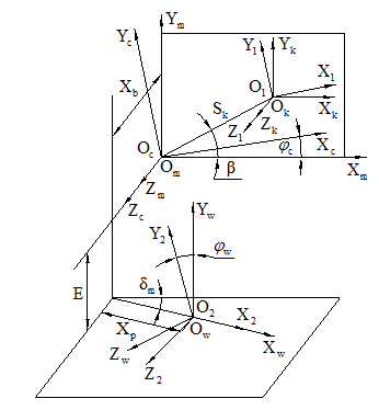
Figure 7 Machining coordinate system of heavy duty spiral bevel gear machine tool.

  1. Calculating motion parameters
  2. The essence of machining heavy-duty spiral bevel gear is to achieve the relative movements between cutter and workpiece gear. It needs to transform the coordinate systems of cutter and workpiece gear to a same coordinate system so as to calculate the relative movement and relative position between cutter and workpiece gear during the process of machining heavy-duty spiral bevel gear.

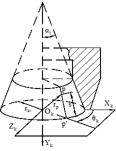
    In the schematic of alternate blade cutter (shown as Figure 8), the r ki MathType@MTEF@5@5@+= feaagKart1ev2aqatCvAUfeBSjuyZL2yd9gzLbvyNv2CaerbuLwBLn hiov2DGi1BTfMBaeXatLxBI9gBaerbd9wDYLwzYbItLDharqqtubsr 4rNCHbGeaGqipu0Je9sqqrpepC0xbbL8F4rqqrFfpeea0xe9Lq=Jc9 vqaqpepm0xbba9pwe9Q8fs0=yqaqpepae9pg0FirpepeKkFr0xfr=x fr=xb9adbaqaaeGaciGaaiaabeqaamaabaabaaGcbaqcfaOaaeOCam aaBaaajuaybaGaae4AaiaabMgaaKqbagqaaaaa@3A51@ indicates the cutter point radiu of inner cutting edge, and α i MathType@MTEF@5@5@+= feaagKart1ev2aqatCvAUfeBSjuyZL2yd9gzLbvyNv2CaerbuLwBLn hiov2DGi1BTfMBaeXatLxBI9gBaerbd9wDYLwzYbItLDharqqtubsr 4rNCHbGeaGqipu0Je9sqqrpepC0xbbL8F4rqqrFfpeea0xe9Lq=Jc9 vqaqpepm0xbba9pwe9Q8fs0=yqaqpepae9pg0FirpepeKkFr0xfr=x fr=xb9adbaqaaeGaciGaaiaabeqaamaabaabaaGcbaqcfaOaaeySdm aaBaaajuaybaGaaeyAaaqabaaaaa@3917@ indicates the pressure angle of inner cutting edge. The element of cone through point P on the circular conical surface of inner cutting edge intersects the knifepoint plane at point P' MathType@MTEF@5@5@+= feaagKart1ev2aqatCvAUfeBSjuyZL2yd9gzLbvyNv2CaerbuLwBLn hiov2DGi1BTfMBaeXatLxBI9gBaerbd9wDYLwzYbItLDharqqtubsr 4rNCHbGeaGqipu0Je9sqqrpepC0xbbL8F4rqqrFfpeea0xe9Lq=Jc9 vqaqpepm0xbba9pwe9Q8fs0=yqaqpepae9pg0FirpepeKkFr0xfr=x fr=xb9adbaqaaeGaciGaaiaabeqaamaabaabaaGcbaqcfaOaaeiuai aabEcaaaa@37E2@ . Assuming | PP' | MathType@MTEF@5@5@+= feaagKart1ev2aqatCvAUfeBSjuyZL2yd9gzLbvyNv2CaerbuLwBLn hiov2DGi1BTfMBaeXatLxBI9gBaerbd9wDYLwzYbItLDharqqtubsr 4rNCHbGeaGqipu0Je9sqqrpepC0xbbL8F4rqqrFfpeea0xe9Lq=Jc9 vqaqpepm0xbba9pwe9Q8fs0=yqaqpepae9pg0FirpepeKkFr0xfr=x fr=xb9adbaqaaeGaciGaaiaabeqaamaabaabaaGcbaqcfa4aaqWaae aacaqGqbGaaeiuaiaabEcaaiaawEa7caGLiWoaaaa@3BD7@ is equal to s MathType@MTEF@5@5@+= feaagKart1ev2aqatCvAUfeBSjuyZL2yd9gzLbvyNv2CaerbuLwBLn hiov2DGi1BTfMBaeXatLxBI9gBaerbd9wDYLwzYbItLDharqqtubsr 4rNCHbGeaGqipu0Je9sqqrpepC0xbbL8F4rqqrFfpeea0xe9Lq=Jc9 vqaqpepm0xbba9pwe9Q8fs0=yqaqpepae9pg0FirpepeKkFr0xfr=x fr=xb9adbaqaaeGaciGaaiaabeqaamaabaabaaGcbaqcfaOaam4Caa aa@375D@ , and θ k MathType@MTEF@5@5@+= feaagKart1ev2aqatCvAUfeBSjuyZL2yd9gzLbvyNv2CaerbuLwBLn hiov2DGi1BTfMBaeXatLxBI9gBaerbd9wDYLwzYbItLDharqqtubsr 4rNCHbGeaGqipu0Je9sqqrpepC0xbbL8F4rqqrFfpeea0xe9Lq=Jc9 vqaqpepm0xbba9pwe9Q8fs0=yqaqpepae9pg0FirpepeKkFr0xfr=x fr=xb9adbaqaaeGaciGaaiaabeqaamaabaabaaGcbaqcfaOaaeiUdm aaBaaajuaybaGaae4Aaaqabaaaaa@3920@ indicates the phase angle at point P on the cutter. therefore, the radius vector of point P can be presented as r p k ,s) MathType@MTEF@5@5@+= feaagKart1ev2aqatCvAUfeBSjuyZL2yd9gzLbvyNv2CaerbuLwBLn hiov2DGi1BTfMBaeXatLxBI9gBaerbd9wDYLwzYbItLDharqqtubsr 4rNCHbGeaGqipu0Je9sqqrpepC0xbbL8F4rqqrFfpeea0xe9Lq=Jc9 vqaqpepm0xbba9pwe9Q8fs0=yqaqpepae9pg0FirpepeKkFr0xfr=x fr=xb9adbaqaaeGaciGaaiaabeqaamaabaabaaGcbaqcfaOaaeOCam aaBaaajuaybaGaaeiCaaqcfayabaGaaeikaiaabI7adaWgaaqcfawa aiaabUgaaeqaaKqbakaabYcacaqGZbGaaeykaaaa@3FAF@ in the cutter coordinate system by the parameters s MathType@MTEF@5@5@+= feaagKart1ev2aqatCvAUfeBSjuyZL2yd9gzLbvyNv2CaerbuLwBLn hiov2DGi1BTfMBaeXatLxBI9gBaerbd9wDYLwzYbItLDharqqtubsr 4rNCHbGeaGqipu0Je9sqqrpepC0xbbL8F4rqqrFfpeea0xe9Lq=Jc9 vqaqpepm0xbba9pwe9Q8fs0=yqaqpepae9pg0FirpepeKkFr0xfr=x fr=xb9adbaqaaeGaciGaaiaabeqaamaabaabaaGcbaqcfaOaam4Caa aa@375D@ and θ k MathType@MTEF@5@5@+= feaagKart1ev2aqatCvAUfeBSjuyZL2yd9gzLbvyNv2CaerbuLwBLn hiov2DGi1BTfMBaeXatLxBI9gBaerbd9wDYLwzYbItLDharqqtubsr 4rNCHbGeaGqipu0Je9sqqrpepC0xbbL8F4rqqrFfpeea0xe9Lq=Jc9 vqaqpepm0xbba9pwe9Q8fs0=yqaqpepae9pg0FirpepeKkFr0xfr=x fr=xb9adbaqaaeGaciGaaiaabeqaamaabaabaaGcbaqcfaOaaeiUdm aaBaaajuaybaGaae4Aaaqabaaaaa@3920@ .

Figure 8 The schematic diagram of alternate blade cutter of heavy duty spiral bevel gear machine tool.

    r p ( θ k ,s)=[ ( r kn ± s n sin α n )cos θ k ( r kn ± s n sin α n )sin θ k s n cos α n ] { += inner cutting edge = outside cutting edge MathType@MTEF@5@5@+= feaagKart1ev2aqatCvAUfeBSjuyZL2yd9gzLbvyNv2CaerbuLwBLn hiov2DGi1BTfMBaeXatLxBI9gBaerbd9wDYLwzYbItLDharqqtubsr 4rNCHbGeaGqipu0Je9sqqrpepC0xbbL8F4rqqrFfpeea0xe9Lq=Jc9 vqaqpepm0xbba9pwe9Q8fs0=yqaqpepae9pg0FirpepeKkFr0xfr=x fr=xb9adbaqaaeGaciGaaiaabeqaamaabaabaaGceaqabeaajuaGca WGYbWaaSbaaKqbGfaacaWGWbaajuaGbeaacaGGOaGaeqiUde3aaSba aKqbGfaacaWGRbaajuaGbeaacaGGSaGaam4CaiaacMcacqGH9aqpda WadaqaauaabeqadeaaaeaacaGGOaGaamOCamaaBaaajuaybaGaam4A aiaad6gaaKqbagqaaiabgglaXkaadohadaWgaaqcfawaaiaad6gaaK qbagqaaiGacohacaGGPbGaaiOBaiabeg7aHnaaBaaajuaybaGaamOB aaqabaqcfaOaaiykaiGacogacaGGVbGaai4CaiabeI7aXnaaBaaaju aybaGaam4AaaqcfayabaaabaGaaiikaiaadkhadaWgaaqcfawaaiaa dUgacaWGUbaabeaajuaGcqGHXcqScaWGZbWaaSbaaKqbGfaacaWGUb aajuaGbeaaciGGZbGaaiyAaiaac6gacqaHXoqydaWgaaqcfawaaiaa d6gaaKqbagqaaiaacMcaciGGZbGaaiyAaiaac6gacqaH4oqCdaWgaa qcfawaaiaadUgaaeqaaaqcfayaaiabgkHiTiaadohadaWgaaqcfawa aiaad6gaaKqbagqaaiGacogacaGGVbGaai4Caiabeg7aHnaaBaaaju aybaGaamOBaaqcfayabaaaaaGaay5waiaaw2faaaGcbaqcfa4aaiqa aqaabeqaaiabgUcaRiabg2da9iaabccacaqGPbGaaeOBaiaab6gaca qGLbGaaeOCaiaabccacaqGJbGaaeyDaiaabshacaqG0bGaaeyAaiaa b6gacaqGNbGaaeiiaiaabwgacaqGKbGaae4zaiaabwgaaeaacqGHsi slcqGH9aqpcaqGGaGaae4BaiaabwhacaqG0bGaae4CaiaabMgacaqG KbGaaeyzaiaabccacaqGJbGaaeyDaiaabshacaqG0bGaaeyAaiaab6 gacaqGNbGaaeiiaiaabwgacaqGKbGaae4zaiaabwgaaaGaay5Eaaaa aaa@A58D@ (7)

    The unit vector of the normal through pointcan be presented by the parameters θ k MathType@MTEF@5@5@+= feaagKart1ev2aqatCvAUfeBSjuyZL2yd9gzLbvyNv2CaerbuLwBLn hiov2DGi1BTfMBaeXatLxBI9gBaerbd9wDYLwzYbItLDharqqtubsr 4rNCHbGeaGqipu0Je9sqqrpepC0xbbL8F4rqqrFfpeea0xe9Lq=Jc9 vqaqpepm0xbba9pwe9Q8fs0=yqaqpepae9pg0FirpepeKkFr0xfr=x fr=xb9adbaqaaeGaciGaaiaabeqaamaabaabaaGcbaqcfaOaaeiUdm aaBaaajuaybaGaae4Aaaqabaaaaa@3920@ as

    n p ( θ k )=[ ±cos α n cos θ k ±cos α n sin θ k sin α n ] { += inner cutting edge = outside cutting edge MathType@MTEF@5@5@+= feaagKart1ev2aqatCvAUfeBSjuyZL2yd9gzLbvyNv2CaerbuLwBLn hiov2DGi1BTfMBaeXatLxBI9gBaerbd9wDYLwzYbItLDharqqtubsr 4rNCHbGeaGqipu0Je9sqqrpepC0xbbL8F4rqqrFfpeea0xe9Lq=Jc9 vqaqpepm0xbba9pwe9Q8fs0=yqaqpepae9pg0FirpepeKkFr0xfr=x fr=xb9adbaqaaeGaciGaaiaabeqaamaabaabaaGceaqabeaajuaGca WGUbWaaSbaaKqbGfaacaWGWbaabeaajuaGcaGGOaGaeqiUde3aaSba aKqbGfaacaWGRbaajuaGbeaacaGGPaGaeyypa0ZaamWaaeaafaqabe WabaaabaGaeyySaeRaci4yaiaac+gacaGGZbGaeqySde2aaSbaaKqb GfaacaWGUbaajuaGbeaaciGGJbGaai4BaiaacohacqaH4oqCdaWgaa qcfawaaiaadUgaaKqbagqaaaqaaiabgglaXkGacogacaGGVbGaai4C aiabeg7aHnaaBaaajuaybaGaamOBaaqabaqcfaOaci4CaiaacMgaca GGUbGaeqiUde3aaSbaaKqbGfaacaWGRbaabeaaaKqbagaacqGHsisl ciGGZbGaaiyAaiaac6gacqaHXoqydaWgaaqcfawaaiaad6gaaeqaaa aaaKqbakaawUfacaGLDbaaaOqaaKqbaoaaceaaeaqabeaacqGHRaWk cqGH9aqpcaqGGaGaaeyAaiaab6gacaqGUbGaaeyzaiaabkhacaqGGa Gaae4yaiaabwhacaqG0bGaaeiDaiaabMgacaqGUbGaae4zaiaabcca caqGLbGaaeizaiaabEgacaqGLbaabaGaeyOeI0Iaeyypa0Jaaeiiai aab+gacaqG1bGaaeiDaiaabohacaqGPbGaaeizaiaabwgacaqGGaGa ae4yaiaabwhacaqG0bGaaeiDaiaabMgacaqGUbGaae4zaiaabccaca qGLbGaaeizaiaabEgacaqGLbaaaiaawUhaaaaaaa@9024@ (8)

    According to the machine coordinate system of heavy-duty spiral bevel gear machine tool, the coordinate-transformation matrix from cutter coordinate system to machine coordinate system can be expressed as

    M mk = M mc M c1 M 1k MathType@MTEF@5@5@+= feaagKart1ev2aaatCvAUfeBSjuyZL2yd9gzLbvyNv2CaerbuLwBLn hiov2DGi1BTfMBaeXatLxBI9gBaerbd9wDYLwzYbItLDharqqtubsr 4rNCHbGeaGqipu0Je9sqqrpepC0xbbL8F4rqqrFfpeea0xe9Lq=Jc9 vqaqpepm0xbba9pwe9Q8fs0=yqaqpepae9pg0FirpepeKkFr0xfr=x fr=xb9adbaqaaeGaciGaaiaabeqaamaabaabaaGcbaqcfaOaamytam aaBaaajuaybaGaamyBaiaadUgaaKqbagqaaiabg2da9iaad2eadaWg aaqcfawaaiaad2gacaWGJbaajuaGbeaacaWGnbWaaSbaaKqbGfaaca WGJbGaaGymaaqcfayabaGaamytamaaBaaajuaybaGaaGymaiaadUga aeqaaaaa@45A2@ (9)

    where M 1k MathType@MTEF@5@5@+= feaagKart1ev2aaatCvAUfeBSjuyZL2yd9gzLbvyNv2CaerbuLwBLn hiov2DGi1BTfMBaeXatLxBI9gBaerbd9wDYLwzYbItLDharqqtubsr 4rNCHbGeaGqipu0Je9sqqrpepC0xbbL8F4rqqrFfpeea0xe9Lq=Jc9 vqaqpepm0xbba9pwe9Q8fs0=yqaqpepae9pg0FirpepeKkFr0xfr=x fr=xb9adbaqaaeGaciGaaiaabeqaamaabaabaaGcbaqcfaOaamytam aaBaaajuaybaGaaGymaiaadUgaaeqaaaaa@3970@ is the coordinate-transformation matrix from coordinate system Σk to auxiliary coordinate system Σ1,

    M 1k =[ cos θ k sin θ k 0 0 sin θ k cos θ k 0 0 0 0 1 0 0 0 0 1 ] MathType@MTEF@5@5@+= feaagKart1ev2aaatCvAUfeBSjuyZL2yd9gzLbvyNv2CaerbuLwBLn hiov2DGi1BTfMBaeXatLxBI9gBaerbd9wDYLwzYbItLDharqqtubsr 4rNCHbGeaGqipu0Je9sqqrpepC0xbbL8F4rqqrFfpeea0xe9Lq=Jc9 vqaqpepm0xbba9pwe9Q8fs0=yqaqpepae9pg0FirpepeKkFr0xfr=x fr=xb9adbaqaaeGaciGaaiaabeqaamaabaabaaGcbaqcfaOaamytam aaBaaajuaybaGaaGymaiaadUgaaeqaaKqbakabg2da9maadmaabaqb aeqabqabaaaaaeaaciGGJbGaai4BaiaacohacqaH4oqCdaWgaaqcfa waaiaadUgaaKqbagqaaaqaaiGacohacaGGPbGaaiOBaiabeI7aXnaa BaaajuaybaGaam4AaaqcfayabaaabaGaaGimaaqaaiaaicdaaeaacq GHsislciGGZbGaaiyAaiaac6gacqaH4oqCdaWgaaqcfawaaiaadUga aeqaaaqcfayaaiGacogacaGGVbGaai4CaiabeI7aXnaaBaaajuayba Gaam4AaaqcfayabaaabaGaaGimaaqaaiaaicdaaeaacaaIWaaabaGa aGimaaqaaiaaigdaaeaacaaIWaaabaGaaGimaaqaaiaaicdaaeaaca aIWaaabaGaaGymaaaaaiaawUfacaGLDbaaaaa@611F@ (10)

    M c1 MathType@MTEF@5@5@+= feaagKart1ev2aaatCvAUfeBSjuyZL2yd9gzLbvyNv2CaerbuLwBLn hiov2DGi1BTfMBaeXatLxBI9gBaerbd9wDYLwzYbItLDharqqtubsr 4rNCHbGeaGqipu0Je9sqqrpepC0xbbL8F4rqqrFfpeea0xe9Lq=Jc9 vqaqpepm0xbba9pwe9Q8fs0=yqaqpepae9pg0FirpepeKkFr0xfr=x fr=xb9adbaqaaeGaciGaaiaabeqaamaabaabaaGcbaqcfaOaamytam aaBaaajuaybaGaam4yaiaaigdaaeqaaaaa@3968@ is the coordinate-transformation matrix from auxiliary coordinate system Σ1 to coordinate system Σc,

    M c1 =[ 1 0 0 s k cosβ 0 1 0 s k sinβ 0 0 1 0 0 0 0 1 ] MathType@MTEF@5@5@+= feaagKart1ev2aaatCvAUfeBSjuyZL2yd9gzLbvyNv2CaerbuLwBLn hiov2DGi1BTfMBaeXatLxBI9gBaerbd9wDYLwzYbItLDharqqtubsr 4rNCHbGeaGqipu0Je9sqqrpepC0xbbL8F4rqqrFfpeea0xe9Lq=Jc9 vqaqpepm0xbba9pwe9Q8fs0=yqaqpepae9pg0FirpepeKkFr0xfr=x fr=xb9adbaqaaeGaciGaaiaabeqaamaabaabaaGcbaqcfaOaamytam aaBaaajuaybaGaam4yaiaaigdaaeqaaKqbakabg2da9maadmaabaqb aeqabqabaaaaaeaacaaIXaaabaGaaGimaaqaaiaaicdaaeaacaWGZb WaaSbaaKqbGfaacaWGRbaabeaajuaGciGGJbGaai4BaiaacohacqaH YoGyaeaacaaIWaaabaGaaGymaaqaaiaaicdaaeaacqWItisBcaWGZb WaaSbaaKqbGfaacaWGRbaajuaGbeaaciGGZbGaaiyAaiaac6gacqaH YoGyaeaacaaIWaaabaGaaGimaaqaaiaaigdaaeaacaaIWaaabaGaaG imaaqaaiaaicdaaeaacaaIWaaabaGaaGymaaaaaiaawUfacaGLDbaa aaa@5768@ (11)

    M mc MathType@MTEF@5@5@+= feaagKart1ev2aaatCvAUfeBSjuyZL2yd9gzLbvyNv2CaerbuLwBLn hiov2DGi1BTfMBaeXatLxBI9gBaerbd9wDYLwzYbItLDharqqtubsr 4rNCHbGeaGqipu0Je9sqqrpepC0xbbL8F4rqqrFfpeea0xe9Lq=Jc9 vqaqpepm0xbba9pwe9Q8fs0=yqaqpepae9pg0FirpepeKkFr0xfr=x fr=xb9adbaqaaeGaciGaaiaabeqaamaabaabaaGcbaqcfaOaamytam aaBaaajuaybaGaamyBaiaadogaaeqaaaaa@399F@ is the coordinate-transformation matrix from coordinate system Σc to coordinate system Σm,

    M mc =[ cos φ c sin φ c 0 0 sin φ c cos φ c 0 0 0 0 1 0 0 0 0 1 ] MathType@MTEF@5@5@+= feaagKart1ev2aaatCvAUfeBSjuyZL2yd9gzLbvyNv2CaerbuLwBLn hiov2DGi1BTfMBaeXatLxBI9gBaerbd9wDYLwzYbItLDharqqtubsr 4rNCHbGeaGqipu0Je9sqqrpepC0xbbL8F4rqqrFfpeea0xe9Lq=Jc9 vqaqpepm0xbba9pwe9Q8fs0=yqaqpepae9pg0FirpepeKkFr0xfr=x fr=xb9adbaqaaeGaciGaaiaabeqaamaabaabaaGcbaqcfaOaamytam aaBaaajuaybaGaamyBaiaadogaaeqaaKqbakabg2da9maadmaabaqb aeqabqabaaaaaeaaciGGJbGaai4BaiaacohacqaHgpGAdaWgaaqcfa waaiaadogaaeqaaaqcfayaaiabgkHiTiGacohacaGGPbGaaiOBaiab eA8aQnaaBaaajuaybaGaam4yaaqabaaajuaGbaGaaGimaaqaaiaaic daaeaaciGGZbGaaiyAaiaac6gacqaHgpGAdaWgaaqcfawaaiaadoga aeqaaaqcfayaaiGacogacaGGVbGaai4CaiabeA8aQnaaBaaajuayba Gaam4yaaqcfayabaaabaGaaGimaaqaaiaaicdaaeaacaaIWaaabaGa aGimaaqaaiaaigdaaeaacaaIWaaabaGaaGimaaqaaiaaicdaaeaaca aIWaaabaGaaGymaaaaaiaawUfacaGLDbaaaaa@614A@ (12)

    The radius vector of pointand the unit vector of the normal through point P is described as

    r p (m) = M mk = M mc M c1 M 1k r p ( θ k , s k ) MathType@MTEF@5@5@+= feaagKart1ev2aqatCvAUfeBSjuyZL2yd9gzLbvyNv2CaerbuLwBLn hiov2DGi1BTfMBaeXatLxBI9gBaerbd9wDYLwzYbItLDharqqtubsr 4rNCHbGeaGqipu0Je9sqqrpepC0xbbL8F4rqqrFfpeea0xe9Lq=Jc9 vqaqpepm0xbba9pwe9Q8fs0=yqaqpepae9pg0FirpepeKkFr0xfr=x fr=xb9adbaqaaeGaciGaaiaabeqaamaabaabaaGcbaqcfaOaamOCam aaBaaajuaybaGaamiCaaqcfayabaWaaWbaaKqbGfqabaGaaiikaiaa d2gacaGGPaaaaKqbakabg2da9iaad2eadaWgaaqcfawaaiaad2gaca WGRbaabeaajuaGcqGH9aqpcaWGnbWaaSbaaKqbGfaacaWGTbGaam4y aaqabaqcfaOaamytamaaBaaajuaybaGaam4yaiaaigdaaeqaaKqbak aad2eadaWgaaqcfawaaiaaigdacaWGRbaabeaajuaGcaWGYbWaaSba aKqbGfaacaWGWbaajuaGbeaacaGGOaGaeqiUde3aaSbaaKqbGfaaca WGRbaajuaGbeaacaGGSaGaam4CamaaBaaajuaybaGaam4Aaaqcfaya baGaaiykaaaa@5983@ (13)

    n p (m) = L mc L c1 L 1k n p ( θ k ) MathType@MTEF@5@5@+= feaagKart1ev2aqatCvAUfeBSjuyZL2yd9gzLbvyNv2CaerbuLwBLn hiov2DGi1BTfMBaeXatLxBI9gBaerbd9wDYLwzYbItLDharqqtubsr 4rNCHbGeaGqipu0Je9sqqrpepC0xbbL8F4rqqrFfpeea0xe9Lq=Jc9 vqaqpepm0xbba9pwe9Q8fs0=yqaqpepae9pg0FirpepeKkFr0xfr=x fr=xb9adbaqaaeGaciGaaiaabeqaamaabaabaaGcbaqcfaOaamOBam aaBaaajuaybaGaamiCaaqcfayabaWaaWbaaKqbGfqabaGaaiikaiaa d2gacaGGPaaaaKqbakabg2da9iaadYeadaWgaaqcfawaaiaad2gaca WGJbaabeaajuaGcaWGmbWaaSbaaKqbGfaacaWGJbGaaGymaaqabaqc faOaamitamaaBaaabaqcfaMaaGymaiaadUgaaKqbagqaaiaad6gada WgaaqcfawaaiaadchaaKqbagqaaiaacIcacqaH4oqCdaWgaaqcfawa aiaadUgaaKqbagqaaiaacMcaaaa@50EC@ (14)

    where L is 3×3 coordinate-transformation matrix which is obtained from the corresponding M in which the last line and the last column are removed. In the same way, the radius vector r q (m) MathType@MTEF@5@5@+= feaagKart1ev2aqatCvAUfeBSjuyZL2yd9gzLbvyNv2CaerbuLwBLn hiov2DGi1BTfMBaeXatLxBI9gBaerbd9wDYLwzYbItLDharqqtubsr 4rNCHbGeaGqipu0Je9sqqrpepC0xbbL8F4rqqrFfpeea0xe9Lq=Jc9 vqaqpepm0xbba9pwe9Q8fs0=yqaqpepae9pg0FirpepeKkFr0xfr=x fr=xb9adbaqaaeGaciGaaiaabeqaamaabaabaaGcbaqcfaOaaeOCam aaBaaajuaybaGaaeyCaaqabaqcfa4aaWbaaKqbGfqabaGaaeikaiaa b2gacaqGPaaaaaaa@3C42@ of point G on the work piece gear which meshes with the pointis shown as

    r q (m) = M m2 M 2w r q MathType@MTEF@5@5@+= feaagKart1ev2aqatCvAUfeBSjuyZL2yd9gzLbvyNv2CaerbuLwBLn hiov2DGi1BTfMBaeXatLxBI9gBaerbd9wDYLwzYbItLDharqqtubsr 4rNCHbGeaGqipu0Je9sqqrpepC0xbbL8F4rqqrFfpeea0xe9Lq=Jc9 vqaqpepm0xbba9pwe9Q8fs0=yqaqpepae9pg0FirpepeKkFr0xfr=x fr=xb9adbaqaaeGaciGaaiaabeqaamaabaabaaGcbaqcfaOaamOCam aaBaaajuaybaGaamyCaaqabaqcfa4aaWbaaeqajuaybaGaaiikaiaa d2gacaGGPaaaaKqbakabg2da9iaad2eadaWgaaqcfawaaiaad2gaca aIYaaajuaGbeaacaWGnbWaaSbaaKqbGfaacaaIYaGaam4Daaqabaqc faOaamOCamaaBaaajuaybaGaamyCaaqcfayabaaaaa@482C@ (15)

    where r q (m) MathType@MTEF@5@5@+= feaagKart1ev2aqatCvAUfeBSjuyZL2yd9gzLbvyNv2CaerbuLwBLn hiov2DGi1BTfMBaeXatLxBI9gBaerbd9wDYLwzYbItLDharqqtubsr 4rNCHbGeaGqipu0Je9sqqrpepC0xbbL8F4rqqrFfpeea0xe9Lq=Jc9 vqaqpepm0xbba9pwe9Q8fs0=yqaqpepae9pg0FirpepeKkFr0xfr=x fr=xb9adbaqaaeGaciGaaiaabeqaamaabaabaaGcbaqcfaOaaeOCam aaBaaajuaybaGaaeyCaaqabaqcfa4aaWbaaKqbGfqabaGaaeikaiaa b2gacaqGPaaaaaaa@3C42@ is the radial vector of pointin the coordinate system of workpiece gear.

    During the process of machining spiral bevel gears, the speed of relative movement between point P on cutting edge’s surface and point G on work piece gear is expressed as

    v (kw) = v k (m) - v w (m) = d r k (m) dt - d r w (m) dt MathType@MTEF@5@5@+= feaagKart1ev2aqatCvAUfeBSjuyZL2yd9gzLbvyNv2CaerbuLwBLn hiov2DGi1BTfMBaeXatLxBI9gBaerbd9wDYLwzYbItLDharqqtubsr 4rNCHbGeaGqipu0Je9sqqrpepC0xbbL8F4rqqrFfpeea0xe9Lq=Jc9 vqaqpepm0xbba9pwe9Q8fs0=yqaqpepae9pg0FirpepeKkFr0xfr=x fr=xb9adbaqaaeGaciGaaiaabeqaamaabaabaaGcbaqcfaOaamODam aaCaaajuaybeqaaiaacIcacaWGRbGaam4DaiaacMcaaaqcfaOaeyyp a0JaamODamaaDaaajuaybaGaam4AaaqaaiaacIcacaWGTbGaaiykaa aajuaGcaGGTaGaamODamaaDaaajuaybaGaam4DaaqaaiaacIcacaWG TbGaaiykaaaajuaGcqGH9aqpdaWcaaqaaiaabsgacaWGYbWaa0baaK qbGfaacaWGRbaabaGaaiikaiaad2gacaGGPaaaaaqcfayaaiaabsga caWG0baaaiaac2cadaWcaaqaaiaabsgacaWGYbWaa0baaKqbGfaaca WG3baabaGaaiikaiaad2gacaGGPaaaaaqcfayaaiaabsgacaWG0baa aaaa@5A3F@ (16)

    Generating gear and workpiece gear should be satisfied with the meshing equation and the transmission ratio

    n p (m) v (kw) =0 MathType@MTEF@5@5@+= feaagKart1ev2aqatCvAUfeBSjuyZL2yd9gzLbvyNv2CaerbuLwBLn hiov2DGi1BTfMBaeXatLxBI9gBaerbd9wDYLwzYbItLDharqqtubsr 4rNCHbGeaGqipu0Je9sqqrpepC0xbbL8F4rqqrFfpeea0xe9Lq=Jc9 vqaqpepm0xbba9pwe9Q8fs0=yqaqpepae9pg0FirpepeKkFr0xfr=x fr=xb9adbaqaaeGaciGaaiaabeqaamaabaabaaGcbaqcfaOaamOBam aaBaaajuaybaGaamiCaaqabaqcfa4aaWbaaKqbGfqabaGaaiikaiaa d2gacaGGPaaaaKqbakabgwSixlaadAhadaahaaqabKqbGfaacaGGOa Gaam4AaiaadEhacaGGPaaaaKqbakabg2da9iaaicdaaaa@463B@ (17)

    m cw = ω c ω w MathType@MTEF@5@5@+= feaagKart1ev2aqatCvAUfeBSjuyZL2yd9gzLbvyNv2CaerbuLwBLn hiov2DGi1BTfMBaeXatLxBI9gBaerbd9wDYLwzYbItLDharqqtubsr 4rNCHbGeaGqipu0Je9sqqrpepC0xbbL8F4rqqrFfpeea0xe9Lq=Jc9 vqaqpepm0xbba9pwe9Q8fs0=yqaqpepae9pg0FirpepeKkFr0xfr=x fr=xb9adbaqaaeGaciGaaiaabeqaamaabaabaaGcbaqcfaOaamyBam aaBaaajuaybaGaam4yaiaadEhaaeqaaKqbakabg2da9maalaaabaGa eqyYdC3aaSbaaKqbGfaacaWGJbaabeaaaKqbagaacqaHjpWDdaWgaa qcfawaaiaadEhaaeqaaaaaaaa@4298@ (18)

    where ω c MathType@MTEF@5@5@+= feaagKart1ev2aqatCvAUfeBSjuyZL2yd9gzLbvyNv2CaerbuLwBLn hiov2DGi1BTfMBaeXatLxBI9gBaerbd9wDYLwzYbItLDharqqtubsr 4rNCHbGeaGqipu0Je9sqqrpepC0xbbL8F4rqqrFfpeea0xe9Lq=Jc9 vqaqpepm0xbba9pwe9Q8fs0=yqaqpepae9pg0FirpepeKkFr0xfr=x fr=xb9adbaqaaeGaciGaaiaabeqaamaabaabaaGcbaqcfaOaaeyYdm aaBaaajuaybaGaae4yaaqcfayabaaaaa@39B7@ and ω w MathType@MTEF@5@5@+= feaagKart1ev2aqatCvAUfeBSjuyZL2yd9gzLbvyNv2CaerbuLwBLn hiov2DGi1BTfMBaeXatLxBI9gBaerbd9wDYLwzYbItLDharqqtubsr 4rNCHbGeaGqipu0Je9sqqrpepC0xbbL8F4rqqrFfpeea0xe9Lq=Jc9 vqaqpepm0xbba9pwe9Q8fs0=yqaqpepae9pg0FirpepeKkFr0xfr=x fr=xb9adbaqaaeGaciGaaiaabeqaamaabaabaaGcbaqcfaOaaeyYdm aaBaaajuaybaGaae4Daaqcfayabaaaaa@39CB@ refers to rotational angular velocity of generating gear and workpiece gear respectively, and m cw MathType@MTEF@5@5@+= feaagKart1ev2aqatCvAUfeBSjuyZL2yd9gzLbvyNv2CaerbuLwBLn hiov2DGi1BTfMBaeXatLxBI9gBaerbd9wDYLwzYbItLDharqqtubsr 4rNCHbGeaGqipu0Je9sqqrpepC0xbbL8F4rqqrFfpeea0xe9Lq=Jc9 vqaqpepm0xbba9pwe9Q8fs0=yqaqpepae9pg0FirpepeKkFr0xfr=x fr=xb9adbaqaaeGaciGaaiaabeqaamaabaabaaGcbaqcfaOaaeyBam aaBaaajuaybaGaae4yaiaabEhaaeqaaaaa@39C4@ is the transmission ratio between the generating gear and work piece gear.

    Suppose the initial rotor angles of imaginary crown generating gear and work piece are φ c0 MathType@MTEF@5@5@+= feaagKart1ev2aqatCvAUfeBSjuyZL2yd9gzLbvyNv2CaerbuLwBLn hiov2DGi1BTfMBaeXatLxBI9gBaerbd9wDYLwzYbItLDharqqtubsr 4rNCHbGeaGqipu0Je9sqqrpepC0xbbL8F4rqqrFfpeea0xe9Lq=Jc9 vqaqpepm0xbba9pwe9Q8fs0=yqaqpepae9pg0FirpepeKkFr0xfr=x fr=xb9adbaqaaeGaciGaaiaabeqaamaabaabaaGcbaqcfaOaeqOXdO 2aaSbaaKqbGfaacaqGJbGaaeimaaqcfayabaaaaa@3AD8@ and φ w0 MathType@MTEF@5@5@+= feaagKart1ev2aqatCvAUfeBSjuyZL2yd9gzLbvyNv2CaerbuLwBLn hiov2DGi1BTfMBaeXatLxBI9gBaerbd9wDYLwzYbItLDharqqtubsr 4rNCHbGeaGqipu0Je9sqqrpepC0xbbL8F4rqqrFfpeea0xe9Lq=Jc9 vqaqpepm0xbba9pwe9Q8fs0=yqaqpepae9pg0FirpepeKkFr0xfr=x fr=xb9adbaqaaeGaciGaaiaabeqaamaabaabaaGcbaqcfaOaeqOXdO 2aaSbaaKqbGfaacaqG3bGaaeimaaqcfayabaaaaa@3AEC@ , then the motion parameters of cradle’s rotating axesand work piece’s rotating axesare described as

    C= φ c = φ c0 + 0 t ω c dt MathType@MTEF@5@5@+= feaagKart1ev2aqatCvAUfeBSjuyZL2yd9gzLbvyNv2CaerbuLwBLn hiov2DGi1BTfMBaeXatLxBI9gBaerbd9wDYLwzYbItLDharqqtubsr 4rNCHbGeaGqipu0Je9sqqrpepC0xbbL8F4rqqrFfpeea0xe9Lq=Jc9 vqaqpepm0xbba9pwe9Q8fs0=yqaqpepae9pg0FirpepeKkFr0xfr=x fr=xb9adbaqaaeGaciGaaiaabeqaamaabaabaaGcbaqcfaOaeyiiIa Taam4qaiabg2da9iabeA8aQnaaBaaajuaybaGaam4yaaqabaqcfaOa eyypa0JaeqOXdO2aaSbaaKqbGfaacaWGJbGaaGimaaqabaqcfaOaey 4kaSYaa8qmaeaacqaHjpWDdaWgaaqcfawaaiaadogaaKqbagqaaaqc fawaaiaaicdaaeaacaWG0baajuaGcqGHRiI8aiaabsgacaWG0baaaa@4E69@ (19)

    A= φ w = φ w0 + 0 t ω w dt MathType@MTEF@5@5@+= feaagKart1ev2aqatCvAUfeBSjuyZL2yd9gzLbvyNv2CaerbuLwBLn hiov2DGi1BTfMBaeXatLxBI9gBaerbd9wDYLwzYbItLDharqqtubsr 4rNCHbGeaGqipu0Je9sqqrpepC0xbbL8F4rqqrFfpeea0xe9Lq=Jc9 vqaqpepm0xbba9pwe9Q8fs0=yqaqpepae9pg0FirpepeKkFr0xfr=x fr=xb9adbaqaaeGaciGaaiaabeqaamaabaabaaGcbaqcfaOaeyiiIa Taamyqaiabg2da9iabeA8aQnaaBaaajuaybaGaam4DaaqcfayabaGa eyypa0JaeqOXdO2aaSbaaKqbGfaacaWG3bGaaGimaaqcfayabaGaey 4kaSYaa8qmaeaacqaHjpWDdaWgaaqcfawaaiaadEhaaKqbagqaaaqc fawaaiaaicdaaeaacaWG0baajuaGcqGHRiI8aiaabsgacaWG0baaaa@4EA3@ (20)

    If the modified-roll method is applied to machining pinion spiral bevel gear, the third ordered modification function needs to be considered for the instantaneous variation transmission ratio.

    φ w = 1 m cw [ φ c -D ( φ c ) 2 -E ( φ c ) 3 ] MathType@MTEF@5@5@+= feaagKart1ev2aaatCvAUfeBSjuyZL2yd9gzLbvyNv2CaerbuLwBLn hiov2DGi1BTfMBaeXatLxBI9gBaerbd9wDYLwzYbItLDharqqtubsr 4rNCHbGeaGqipu0Je9sqqrpepC0xbbL8F4rqqrFfpeea0xe9Lq=Jc9 vqaqpepm0xbba9pwe9Q8fs0=yqaqpepae9pg0FirpepeKkFr0xfr=x fr=xb9adbaqaaeGaciGaaiaabeqaamaabaabaaGcbaqcfaOaeqOXdO 2aaSbaaKqbGfaacaWG3baabeaajuaGcqGH9aqpdaWcaaqaaiaaigda aeaacaWGTbWaaSbaaKqbGfaacaWGJbGaam4Daaqcfayabaaaamaadm aabaGaeqOXdO2aaSbaaKqbGfaacaWGJbaabeaajuaGcaGGTaGaamir amaabmaabaGaeqOXdO2aaSbaaKqbGfaacaWGJbaajuaGbeaaaiaawI cacaGLPaaadaahaaqabKqbGfaacaaIYaaaaKqbakaac2cacaWGfbWa aeWaaeaacqaHgpGAdaWgaaqcfawaaiaadogaaKqbagqaaaGaayjkai aawMcaamaaCaaabeqcfawaaiaaiodaaaaajuaGcaGLBbGaayzxaaaa aa@56F2@ (21)

    where D is second order modified roll coefficient, andis third order modified roll coefficient. The motion parameter of work piece gear box’s rotating axes B on the heavy duty spiral bevel gear machine tool is usually equal to workpiece gear’s root angle.

    B= δ m MathType@MTEF@5@5@+= feaagKart1ev2aqatCvAUfeBSjuyZL2yd9gzLbvyNv2CaerbuLwBLn hiov2DGi1BTfMBaeXatLxBI9gBaerbd9wDYLwzYbItLDharqqtubsr 4rNCHbGeaGqipu0Je9sqqrpepC0xbbL8F4rqqrFfpeea0xe9Lq=Jc9 vqaqpepm0xbba9pwe9Q8fs0=yqaqpepae9pg0FirpepeKkFr0xfr=x fr=xb9adbaqaaeGaciGaaiaabeqaamaabaabaaGcbaqcfaOaeyiiIa TaamOqaiabg2da9iabes7aKnaaBaaajuaybaGaamyBaaqcfayabaaa aa@3D84@ (22)

    During the process of machining of the heavy duty spiral bevel gear with the heavy duty spiral bevel gear machine tool, feed motion is achieved by the cutter spindle’s concertina movement along the axes Zk to change the distance between the knifepoint plane and work piece’s root cone.

    Z k =F(t) MathType@MTEF@5@5@+= feaagKart1ev2aaatCvAUfeBSjuyZL2yd9gzLbvyNv2CaerbuLwBLn hiov2DGi1BTfMBaeXatLxBI9gBaerbd9wDYLwzYbItLDharqqtubsr 4rNCHbGeaGqipu0Je9sqqrpepC0xbbL8F4rqqrFfpeea0xe9Lq=Jc9 vqaqpepm0xbba9pwe9Q8fs0=yqaqpepae9pg0FirpepeKkFr0xfr=x fr=xb9adbaqaaeGaciGaaiaabeqaamaabaabaaGcbaqcfaOaamOwam aaBaaajuaybaGaam4AaaqabaqcfaOaeyypa0JaamOraiaacIcacaWG 0bGaaiykaaaa@3D73@ (23)

    Based on the above discussions, we can obtain the heavy duty spiral bevel gear machine tool’s motion parameters or instantaneous relatively position of generating gear and workpiece gear during the process of machining heavy duty spiral bevel gear.

Verification of numerical control machining model

An example of calculating machining parameters of a given heavy-duty spiral bevel gear with the diameter 1600 mm is presented to verify the numerical control machining model of heavy-duty spiral bevel gear CNC machine tool adopting the proposed cutter spindle feed mode . The specifications of the heavy duty-spiral bevel gears are shown in Table 1. The adjusting parameters of the heavy duty-spiral bevel gear machine tool are illustrated in Table 2, and the partial NC code used to drive the motion parameters of numerical control machining model of heavy-duty spiral bevel gear CNC machine tool is described in Table 3.


Pinion

Bull gear

Module  [mm]

16

Shaft angle  [deg]

90

Pressure angle  [deg]

20

Face width  [mm]

120

Helical angle  [deg]

30

Out cone distance  [mm]

797.797

Whole tooth height  [mm]

30.208

Number of teeth            

27

96

Addendum  [mm]

19.36

7.84

Dedendum [mm]

10.848

22.368

Pitch diameter  [mm]

432

1536

Tip diameter  [mm]

469.274

1540.245

Circular tooth thickness  [mm]

30.934

19.331

Pitch angle [deg]

15.709

74.291

Root angle  [deg]

14.93

72.685

Face angle [deg]

17.314

75.07

Table 1 Specifications of the heavy duty spiral bevel gear

Radial cutter spacing  [mm]

653.92

Angular cutter spacing  [deg]

42.282

Eccentric angle [deg]

63.654

Cradle angle [deg]

74.109

Horizontal blank offset  [mm]

0

Vertical blank offset  [mm]

0

Machine root angle [deg]

72.685

Transmission ratio

1.038798

Cutter diameter  [deg]

1016

Cutter point width  [mm]

11.35

Table 2 Adjusting parameters of heavy duty spiral bevel gear machine tool

 No

C MathType@MTEF@5@5@+= feaagKart1ev2aqatCvAUfeBSjuyZL2yd9gzLbvyNv2CaerbuLwBLn hiov2DGi1BTfMBaeXatLxBI9gBaerbd9wDYLwzYbItLDharqqtubsr 4rNCHbGeaGqipu0Je9sqqrpepC0xbbL8F4rqqrFfpeea0xe9Lq=Jc9 vqaqpepm0xbba9pwe9Q8fs0=yqaqpepae9pg0FirpepeKkFr0xfr=x fr=xb9adbaqaaeGaciGaaiaabeqaamaabaabaaGcbaqcfaOaeyiiIa Taam4qaaaa@38CB@

/( ° ) MathType@MTEF@5@5@+= feaagKart1ev2aaatCvAUfeBSjuyZL2yd9gzLbvyNv2CaerbuLwBLn hiov2DGi1BTfMBaeXatLxBI9gBaerbd9wDYLwzYbItLDharqqtubsr 4rNCHbGeaGqipu0Je9sqqrpepC0xbbL8F4rqqrFfpeea0xe9Lq=Jc9 vqaqpepm0xbba9pwe9Q8fs0=yqaqpepae9pg0FirpepeKkFr0xfr=x fr=xb9adbaqaaeGaciGaaiaabeqaamaabaabaaGcbaqcfaieaaaaaa aaa8qacaGGVaWdamaabmaabaWdbiabgclaWcWdaiaawIcacaGLPaaa aaa@3ADA@

A MathType@MTEF@5@5@+= feaagKart1ev2aqatCvAUfeBSjuyZL2yd9gzLbvyNv2CaerbuLwBLn hiov2DGi1BTfMBaeXatLxBI9gBaerbd9wDYLwzYbItLDharqqtubsr 4rNCHbGeaGqipu0Je9sqqrpepC0xbbL8F4rqqrFfpeea0xe9Lq=Jc9 vqaqpepm0xbba9pwe9Q8fs0=yqaqpepae9pg0FirpepeKkFr0xfr=x fr=xb9adbaqaaeGaciGaaiaabeqaamaabaabaaGcbaqcfaOaeyiiIa Taamyqaaaa@38C9@

/( ° ) MathType@MTEF@5@5@+= feaagKart1ev2aaatCvAUfeBSjuyZL2yd9gzLbvyNv2CaerbuLwBLn hiov2DGi1BTfMBaeXatLxBI9gBaerbd9wDYLwzYbItLDharqqtubsr 4rNCHbGeaGqipu0Je9sqqrpepC0xbbL8F4rqqrFfpeea0xe9Lq=Jc9 vqaqpepm0xbba9pwe9Q8fs0=yqaqpepae9pg0FirpepeKkFr0xfr=x fr=xb9adbaqaaeGaciGaaiaabeqaamaabaabaaGcbaqcfaieaaaaaa aaa8qacaGGVaWdamaabmaabaWdbiabgclaWcWdaiaawIcacaGLPaaa aaa@3ADA@

B MathType@MTEF@5@5@+= feaagKart1ev2aqatCvAUfeBSjuyZL2yd9gzLbvyNv2CaerbuLwBLn hiov2DGi1BTfMBaeXatLxBI9gBaerbd9wDYLwzYbItLDharqqtubsr 4rNCHbGeaGqipu0Je9sqqrpepC0xbbL8F4rqqrFfpeea0xe9Lq=Jc9 vqaqpepm0xbba9pwe9Q8fs0=yqaqpepae9pg0FirpepeKkFr0xfr=x fr=xb9adbaqaaeGaciGaaiaabeqaamaabaabaaGcbaqcfaOaeyiiIa TaamOqaaaa@38CA@

/( ° ) MathType@MTEF@5@5@+= feaagKart1ev2aaatCvAUfeBSjuyZL2yd9gzLbvyNv2CaerbuLwBLn hiov2DGi1BTfMBaeXatLxBI9gBaerbd9wDYLwzYbItLDharqqtubsr 4rNCHbGeaGqipu0Je9sqqrpepC0xbbL8F4rqqrFfpeea0xe9Lq=Jc9 vqaqpepm0xbba9pwe9Q8fs0=yqaqpepae9pg0FirpepeKkFr0xfr=x fr=xb9adbaqaaeGaciGaaiaabeqaamaabaabaaGcbaqcfaieaaaaaa aaa8qacaGGVaWdamaabmaabaWdbiabgclaWcWdaiaawIcacaGLPaaa aaa@3ADA@

Z k MathType@MTEF@5@5@+= feaagKart1ev2aaatCvAUfeBSjuyZL2yd9gzLbvyNv2CaerbuLwBLn hiov2DGi1BTfMBaeXatLxBI9gBaerbd9wDYLwzYbItLDharqqtubsr 4rNCHbGeaGqipu0Je9sqqrpepC0xbbL8F4rqqrFfpeea0xe9Lq=Jc9 vqaqpepm0xbba9pwe9Q8fs0=yqaqpepae9pg0FirpepeKkFr0xfr=x fr=xb9adbaqaaeGaciGaaiaabeqaamaabaabaaGcbaqcfaOaamOwam aaBaaabaGaae4Aaaqabaaaaa@3852@

/mm MathType@MTEF@5@5@+= feaagKart1ev2aaatCvAUfeBSjuyZL2yd9gzLbvyNv2CaerbuLwBLn hiov2DGi1BTfMBaeXatLxBI9gBaerbd9wDYLwzYbItLDharqqtubsr 4rNCHbGeaGqipu0Je9sqqrpepC0xbbL8F4rqqrFfpeea0xe9Lq=Jc9 vqaqpepm0xbba9pwe9Q8fs0=yqaqpepae9pg0FirpepeKkFr0xfr=x fr=xb9adbaqaaeGaciGaaiaabeqaamaabaabaaGcbaqcfaieaaaaaa aaa8qacaGGVaGaamyBaiaad2gaaaa@391B@

N3330

34.888

22.61

72.685

-25.36

N3340

34.994

22.72

72.685

-25.36

N3350

35.1

22.83

72.685

-25.36

N3360

35.206

22.94

72.685

-25.36

N4280

44.958

33.071

72.685

-25.36

N4290

45.064

33.181

72.685

-25.36

N4300

45.17

33.291

72.685

-25.36

N4310

45.276

33.401

72.685

-25.36

Table 3 NC machining parameters of the virtual simulation heavy duty spiral bevel gear machine tool

Validation of proposed feed mode through virtual simulation and experimental models

To validate the feasibility and effectiveness of the proposed cutter spindle feed mode, a virtual simulation machining model and an experimental model for heavy-duty spiral bevel gear CNC machine tool are established. The virtual simulation machining model is constructed using simulation machining software VERICUT and the experimental model is built on a bull heavy-duty spiral bevel gear CNC machine tool. Virtual simulation machining on a given pair of heavy-duty spiral bevel gears has been conducted using motion parameters which are derived from the methods expressed in section 3. Virtual machining simulations on a bull heavy-duty spiral bevel gear and a pinion spiral bevel gear are illustrated in Figure 9A & 9B respectively. The practical machining is performed on a bull heavy-duty spiral bevel gear using the CNC machine tool adopting cutter spindle feed mode as shown in Figure 10. Both the virtual simulation machining and practical machining results indicate that the proposed cutter spindle feed mode used for heavy-duty spiral bevel gear CNC machine tool is feasible and effective and meet the expected design requirements.

Figure 9 The virtual simulation machining of heavy duty spiral bevel gears. (A) Virtual simulation machining on bull gear. (B) virtual simulation machining on pinion gear.

Figure 10 Machining on one bull heavy duty spiral bevel gear.

Conclusion

  1. A novel cutter spindle feed mode replacing the traditional workpiece or spindle box feed mode for heavy-duty spiral bevel gear CNC machine tool is proposed.
  2. Structural model and numerical control machining model of heavy-duty spiral bevel gear CNC machine tool adopting the proposed cutter spindle feed mode are established respectively. In the numerical control machining model, cutter location parameters are first determined, and then the machining coordinate system is established and the motion parameters are calculated. The numerical control machining model is verified by an illustrative example.
  3. A virtual simulation machining model and an experimental machining model are established respectively. And the feasibility and effectiveness of the proposed cutter spindle feed mode is validated through conducting machining heavy-duty spiral bevel gears with diameter 1600 mm on both the virtual simulation machining model and the experimental machining model. Both the virtual simulation machining and practical machining results show that the proposed cutter spindle feed mode is feasible and effective with improved machining efficiency and accuracy.

Acknowledgements

The authors are grateful for the financial support of the National Natural Science Foundation of China under grant No. 51305127 and youth backbone teacher in Colleges and Universities training program of Henan Province of China No. 2016GGJS-040.

Conflicts of interest

The author declares there are no conflicts of interest.

References

  1. Litvin FL, Alfonso F. Gear’s geometry and applied theory. 2th ed.Cambridge University Press; 2004. p. 633–644.
  2. Zeng T. Design and machining of spiral bevel gear. China:Harbin Institute of Technology Press; 1989. p. 90–91.
  3. Takayuki N. Computerized Modeling and Loaded Tooth Contact Analysis of Hypoid Gears Manufactured by Face Hobbing Process. Journal of Advanced Mechanical Design, Systems, and Manufacturing. 2009;3(3):224–235.
  4. Simon VV. Optimal machine-tool settings for the manufacture of face-hobbed spiral bevel gears. Journal of Mechanical Design. 2014;136(8).
  5. Simon VV. Machine-tool settings to reduce the sensitivity of spiral bevel gears to tooth errors and misalignments. J Mech Des. 2008;130(8):0826031–08260310.
  6. Simon VV. Optimal machine tool settings for hypoid gears improving load distribution. Journal of Mechanical Design. 2001;12(4):557–582.
  7. Cao XM, Fang ZD, Xu Hao. Design of Pinion Machine Tool-settings for Spiral Bevel Gears by Controlling Contact Path and Transmission Errors. Chinese Journal of Aeronautics. 2008;21(2):179–186.
  8. Litvin FL, Zhang Y, Handschuh RF. Local Synthesis and Tooth Contact Analysis of Face-Milled Spiral Bevel Gears. NASA Contractor Reports. 1991;4342:184.
  9. Sobolewski B, Marciniec A. Method of spiral bevel gear tooth contact analysis performed in CAD environment. Aircraft Engineering and Aerospace Technology. 2013;85(6):467–474.
  10. Vimercati M. Mathematical model for tooth surfaces representation of face-hobbed hypoid gears and its application to contact analysis and stress calculation. Mechanism and Machine Theory. 2007;42(6):668–690.
  11. Argyris J, Fuentes A, Litvin FL. Computerized integrated approach for design and stress analysis of spiral bevel gears. Computer Methods in Applied Mechanics and Engineering. 2002;191(11-12):1057–1095.
  12. Simon VV. Head-cutter for optimal tooth modifications in spiral bevel gears. Mechanism and Machine Theory. 2009;44(7):1420–1435.
  13. Fang ZD, Deng XZ, Ren DF. Loaded tooth contact analysis of spiral bevel gears considering edge contact. Chinese Journal of Mechanical Engineering. 2002;38(9):69–72.
  14. Simon VV. Advanced manufacture of spiral bevel gears on CNC hypoid generating machine. Journal of Mechanical Design. 2010;132(3):0310011–0310018.
  15. Deng XZ, Li GG, Wei BY. Face-milling spiral bevel gear tooth surfaces by application of 5-axis CNC machine tool. The International Journal of Advanced Manufacturing Technology. 2014;71(5-8):1049–1057.
  16. Suh SH, JihWS, Hong HD. Sculptured surface machining of spiral bevel gears with CNC milling. International Journal of Machine Tools and Manufacture. 2001;41(6):833–850.
  17. Shih YP, Fong ZH. Flank correction for spiral bevel and hypoid gears on a six-Axis CNC hypoid generator. Journal of Mechanical Design. 2008;130(6):0626041–06260411.
  18. Liu K, Lu YH, Zhao DB. Application of adaptive acceleration-deceleration control method of parametric curve interpolator in spiral bevel gear NC machining. Journal of Mechanical Engineering. 2009;45(12):198–204.
  19. Fan Q. Computerized modeling and simulation of spiral bevel and hypoid gears manufactured by gleason face hobbing process. Journal of Mechanical Design. 2006;128(6):1315–1327.
  20. Fan Qi. Enhanced algorithms of contact simulation for hypoid gear drives produced by face-milling and face-hobbing processes. Journal of Mechanical Design. 2007;129(1):31–37.
  21. Chao Lin, Yu Fan, Yao Wang, et al. A five-axis CNC machining method of orthogonal variable transmission ratio faces gear. Journal of Advanced Mechanical Design, Systems, and Manufacturing. 2014;8(3):1–12.
  22. ShihYP. A novel ease-off flank modification methodology for spiral bevel and hypoid gears. Mechanism and Machine Theory. 2010;45(8):1108–1124.
  23. Simon VV. Loaded tooth contact analysis and stresses in spiral bevel gears. ASME 2009 International Design Engineering Technical Conferences &Computers and Information in Engineering Conference. 2009;271–279.
  24. SimonVV. Influence of tooth modifications on tooth contact in face-hobbed spiral bevel gears. Mechanism and Machine Theory. 2011;46(12):1980–1998.
  25. Su JZ, He ZX. High-precision modification of tooth surface for spiral bevel gears. Journal of South China University of Technology (Natural Science). 2014;42(4):91–96.
Creative Commons Attribution License

©2018 Yanwei, et al. This is an open access article distributed under the terms of the, which permits unrestricted use, distribution, and build upon your work non-commercially.