
Research Article Volume 8 Issue 3
Adaptive control of AUV trajectory tracking in the presence of disturbance
Mostafa Jalalnezhada 
Regret for the inconvenience: we are taking measures to prevent fraudulent form submissions by extractors and page crawlers. Please type the correct Captcha word to see email ID.

Mechanical Engineering, Kharazmi University of Tehran, Republic of Iran
Correspondence: Mostafa Jalalnezhada, Mechanical Engineering, Kharazmi University of Tehran, Republic of Iran, Tel +98 9171436228
Received: September 16, 2022 | Published: December 6, 2022
Citation: Jalalnezhada M. Adaptive control of AUV trajectory tracking in the presence of disturbance. Int Rob Auto J. 2022;8(3):94-101 DOI: 10.15406/iratj.2022.08.00251
Download PDF
Abstract
In the method used in this article, the control objectives are achieved by using the adaptive controller and based on the first-order sliding mode method, assuming that the disturbance and its derivative are bounded with an indeterminate boundary, in a way that is resistant to uncertainty and disturbance caused by ocean waves. be This method is based on the law of two-layer adaptation, which works without the need of knowledge of the boundary values of disturbance and its derivative. The stability of the proposed robust-adaptive control law is proved using Lyapunov theory and the performance of the designed controller is verified using simulation results. The performance of the proposed controller is evaluated in terms of error and control effort by comparing the simulation results of the proposed control and conventional sliding mode control. According to the results of comparison and investigation in different disturbance scenarios, the tracking error in the proposed control is much less than the tracking error of the conventional sliding mode control, and also, the range of control effort in the conventional sliding mode control is greater and is associated with chattering, if it is in the case of the robust control. - Charting’s proposed adaptation is not observed.
Keywords: AUV, trajectory tracking, sliding mode control, adaptive control
Introduction
The tracking control of the AUV trajectory with three degrees of freedom in the horizontal plane is investigated. Due to the presence of turbulence in the sea and ocean environment as well as uncertainty in AUV parameters, robust control is used to control AUV.1 Conventional sliding mode control as a robust and nonlinear control method is one of the widely used methods for AUVs. But, it leads to the phenomenon of chattering, which is an undesirable phenomenon for the driver circuit and AUV motors.2 The cause of chattering is the range of the switching part of the control signal in the sliding mode control, which is selected according to the disturbance range. The higher the switching control gain, the lower the tracking error and chattering occurs instead. Therefore, a compromise must be made between chattering and tracking error. The combination of adaptive control methods and sliding mode control is effective in reducing chattering while increasing consistency against disturbance. In this way, the disturbance is estimated using adaptive control.3 Using the estimation information, the control effort is calculated and applied to the control system. Therefore, chattering is reduced and consistency against turbulence is also enhanced.4
By using optimal control, it is possible to reduce the range of control effort and improve energy, which is an important issue in controlling AUVs. It is also possible to improve the sliding mode control performance by optimizing the sliding surface.5
In,6 an attempt was made to improve energy damping by combining sliding mode control and optimization. In this way, by using LQR, a sub-optimal control is produced in the neighborhood of the output of the sliding mode control, and it leads to the reduction of the range of control effort and error, in other words, the minimum point is obtained. In,7,8 the sliding control surface of the sliding model was calculated using optimization and with quadratic target warping and used for AUV depth control. In,9 using the PSO optimization method, the sliding surface coefficients were optimized and used to control the depth of AUV.
In,10 using the genetic algorithm, the sliding mode controller coefficients were adjusted to control the depth of AUV.
Due to the weakness of sliding mode control in some cases of chattering phenomenon, it is recommended to use it in combination with other controllers. In some articles, the coefficient of the switching section is estimated using adaptive control, and in some articles, the disturbance is estimated. This greatly helps to reduce chattering phenomenon. In,11 using adaptive control, the parameters in the sliding mode control were estimated and AUV depth control was performed. In,12 using sliding mode control and adaptive control, a control consisting of two loops was designed for AUV. In this way, the time was controlled in the outer ring and a virtual speed was created for the inner ring to control the speeds to reach the desired time. In this article, using single-layer adaptive control, the switching part of sliding mode control was estimated to reduce chattering and to estimate uncertain parameters and disturbances. In,13 a controller was designed using high order and counter-adaptive sliding mode control to control AUV in the horizontal plane and the disturbances were estimated using the adaptive law. According to the comparison results of this controller and high order sliding mode control, the proposed controller has no chattering while the high order sliding mode control has chattering. In,14 the orientation of the AUV is controlled using adaptive-sliding mode control. In which adaptive control is used to estimate the uncertainties of the system and disturbance, and the emphasis is on reducing chattering by using the disturbance estimator.
System modeling
To describe the location and orientation of the AUV in the three-dimensional space to six variables including;
and their derivatives are needed to describe position and linear velocity along the lines of illustrations
and three other variables θ, ϕ and ψ and their derivatives are needed to describe orientation and angular velocity. As shown in Figure 1, AUV movement elements are defined as pitch, roll, heave, sway, surge and yaw, respectively. Figure 1 notation used in this thesis in Table 1 is shown. In order to determine the equations of motion of the AUV, two frames of motion and rigid body are used.
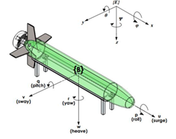
Figure 1 Describe the position and orientation of the AUV.
Marg frame: It is a fixed frame which is considered as Marg and may be matched with the frame of the object in the initial conditions. The position and direction of AUV is expressed in this framework and it is denoted by . Body frame: This frame is shown as
and is a rigid frame that is fixed on the AUV. AUV's linear and angular velocities are described in this framework.15 The detailed orientation of these two frameworks is shown in Figure 1.
Based on Table 1, we define the following vectors
(1)
where,
is the position and direction vector in the frame of Marg, v is the vector of linear and angular velocities in the body frame and τ is the forces and torques applied to the AUV in the body frame. AUV motion equations are divided into two categories.
|
Euler's angles
|
Linear and angular velocities
|
Force and torque
|
|
|
𝑥
|
𝑢
|
𝑋
|
Surge, x
|
|
𝑦
|
𝑣
|
𝑌
|
Sway, y
|
|
𝑧
|
𝑤
|
𝑍
|
Heave, z
|
|
𝜙
|
𝑝
|
𝐾
|
Roll, x
|
|
𝜃
|
𝑞
|
𝑀
|
Pitch, y
|
|
𝜓
|
𝑟
|
𝑁
|
Yaw, z
|
Table 1 Marking related to AUV
Kinematic equations
These equations deal with the geometric aspect of movement, that is, time and orientation.16
- Dynamic equations: these equations describe the forces that lead to movement.
Each of these equations is described in the following sections.
The science of kinematics, apart from examining the forces and torques of the moving agent, models the positional relationship and jump of the AUV with linear and angular velocities. The first derivative of the time vector
is related to the linear velocity vector
through relation (2).
(2)
(3)
Where in;
(4)
is invertible because:
. The first derivative of the time vector
is related to the linear velocity vector
through equation 5.
(5)
In which,
is described as (6):
(6)
By combining the relation (2) and (5), the kinematic equations of AUV are obtained as (7):
(7)
Dynamic Equations
At first, the vectors representing forces, torques, linear and angular velocities are defined as follows:
force distributed in the body frame.
The moment analyzed in the frame of the body.
Linearized velocities decomposed in the frame of the object.
Angular velocities decomposed in the frame of the object relative to the reference frame of the vector from to the center of gravity decomposed in the frame of the object can be seen with data display. Using the Newton-Euler formulation for a rigid body with mass, the relationship between forces and moments is written as (8):
(8)
where the inertia matrix
around
is expressed as (9):
(9)
In relation (8), the motion equation of the rigid body gives the following result:
(10)
where the general velocity vector described in the frame of the body is the general vector of external forces and torques. The inertia matrix of the rigid body system is expressed as (11):
(11)
and the Coriolis matrix of the rigid body , is presented as (12)):
(12)
General force and torque vector
is the sum of hydrodynamic force and torque vector
, external disturbance force and torque vector
and thruster force and torque vector,
.
(13)
Hydrodynamic forces and moments are the forces and moments that are applied to the AUV when it moves inside the water. These forces and torques are in the form of three components:
- Added mass: This component is created by the inertia of the fluid surrounding the object.
- Damping: this component causes the body's movement to be damped.
- Restoring force: This component is caused by the force of buoyancy and weight.
The hydrodynamic force and moments
can be obtained by using the equation (14):
(14)
where the added mass matrix, the Coriolis matrix, the damping matrix and the orientation position of the vector are related to the restoring force and torque. The added mass matrix is obtained from the equation (15):
(15)
The Coriolis matrix is obtained from the equation (16):
(16)
That
(17)
In general, hydrodynamic damping is created due to body friction, wave drift and waves that are emitted from the body and carry energy. The general description of the damping matrix is complex. Although it is customary to write the damping matrix as (18):
(18)
(19)
The non-linear part of the damping is obtained by using the equation (20):
(20)
All members of the above matrix have a numerical value. However, the values of some of them are very small and therefore they are considered zero [89]. The restoring forces and torques are obtained from the equation (20):
(21)
where and are the force of weight and buoyancy, respectively, and can be obtained from the equation (21):
(22)
Where the mass of the object, the acceleration of gravity, the density of the object, and the volume of the fluid displaced by the object are the coordinates of the center of buoyancy and the coordinates of the center of gravity.
AUV motion equations in six degrees of freedom, by placing (14) in (11) and combining it with (7) are obtained as follows
(23)
Where
(24)
The Coriolis matrix for a body moving in a fluid is a quasi-symmetric matrix. that is:
(25)
If the body moves in an ideal fluid; the damping matrix is a real, non-symmetric and positive matrix. that is:
(26)
Design adaptive control
As mentioned, the sliding mode control is a non-linear and robust control, but the presence of constant gain in the switching section leads to the undesirable chattering phenomenon. This stable profit is considered proportional to the limit of disturbance and uncertainty. It is customary to choose a more conservative uncertainty band in the design of the controller to ensure the convergence of currents to the sliding surface. However, this causes chattering to increase. For this reason, sliding-mode adaptive controllers are used to reduce chattering so that the gain of the controller is estimated using the matching law and is as small as possible to avoid chattering and as large as required. Until they converge to the sliding surface and the algorithm is resistant to external disturbances and uncertainties of the system
In short, by using the resilient-adaptive method, a fixed gain is not used to suppress disturbances and the phenomenon of chattering, which is too large for disturbances due to the large gain, is avoided, while, in the event of a large disturbance, control the adjuster has controllable gain and consistency. This method, by using the two-layer matching law, works without the need of disturbance boundary information and its derivative, and the control law is proposed to build the principles of equivalent control, which, unlike the conventional sliding mode control law, is the sum of two parts, equivalent control and control switching.
In this method, the sliding surface is considered as a simple sliding mode control as (26). In order to simplify the relation (27), nonlinear dynamics and disturbance in the derivative of the sliding surface, as an invariant expression is taken and its value is estimated using the adaptive controller:
(27)
Where
(28)
(29)
Provided that
is bounded with a range of
and its derivative is bounded with a limit of
, in this case, the control law is considered as (30) [91]:
(30)
where β is a positive and small constant scalar of design and
is a variable scalar that is adjusted using the matching law. To converge to the sliding surface, the relation (30) must be established:
(31)
By placing the relation (31) in (30), it is possible to obtain:
(32)
By placing (30) in (32), it can be written:
(33)
The relation (32), with a slight simplification, is rewritten as (34):
(34)
from the relation (34) it can be concluded that:
(35)
Therefore, the relation (35) is a sufficient condition for convergence to the sliding surface. During the convergence to the sliding surface,
and
is equal to the equivalent control of
, which is actually the average of is
and it is possible to pass the signal
through a low-pass filter to its approximate value [92]. is from the solution of the algebraic equation
when
, is obtained.
Therefore:
(36)
By passing the switching signal
through a low-pass filter, an approximation of
is obtained in the form (36):
(37)
In the relation (37),
is a time constant and if it is chosen small enough,
becomes small enough and the correct estimate of
is obtained. The adaptation of
is made using equivalent control. By adding a confidence margin and an estimate of
under the condition (38), we can write:
(38)
where 0<μ<1 and
are design scalars and should be chosen in such a way that:
(39)
Now the error variable is considered as (40):
(40)
Note that if
, then Therefore, the problem of the sliding mode becomes a problem whose goal is
. The matching law
is considered as
(41)
where
is the design variable scalar and is an interpretation of the upper limit of the disturbance change rate, and the structure of
is written as (42) below:
(42)
where 𝑟0 is a positive and constant scalar and
is obtained by solving a differential equation (adaptation law). Therefore, in this controller there are two adaptation laws related to
and
, the rate of change of
(first adaptation law) is a function of
which is calculated by the second adaptation law in relation (43) so that
(43)
where
scalar is designed.
is defined as the second matching error as (44):
(44)
where
is the confidence margin variable and the disturbance derivative limit whose value is unknown. In figure (45), the block diagram of the proposed controller is shown (Figure 2).

Figure 2 Block diagram of adaptive sliding mode control for the proposed submarine system.
Proof of stability
According to theorem [91], if we consider the indefinite term d such that
and
be valid and
and
are restricted but unknown. By choosing
in such a way that the relation (45) holds for each
and
, causes it to be blocked in time and as a result the sliding motion is stable.
(44)
The Lyapunov function is considered as (45):
(45)
By deriving from the relation (46), it can be written:
(46)
By placing the relation (46) in (45),
is obtained as follows:
(47)
Also, according to the relation (48), it can be written:
(48)
By placing relation (48) in (47):
(49)
Therefore, (δ̇(𝑡) is obtained as follows:
(50)
where by deriving the relation (50), it can be written:
(51)
From the relation (51) it can be written:
(52)
we know:
(53)
Therefore, using relation (53), relation (52) is obtained:
(54)
Using relation (53), relation (54) can be rewritten as follows:
(55)
The relation (55) is finally rewritten as the relation (56):
(56)
By deriving the relation (57), we can write:
(57)
From the relationship (56) and (57) it can be concluded that:
(58)
Now, to prove the stability, the Lyapunov function plot in terms of and in figure 3 is used. Assuming that
and according to the relation (45), it can be found that
is always positive or zero. Therefore, considering that
will never be negative, from the equation (59), we can write:
(59)
Therefore, only the regions specified in Figure 3 are checked for stability. In the first region, according to the definition of
and
in relation) (45) and (58), it can be written:
(59)
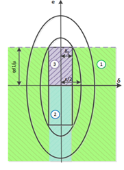
Figure 3 Zoning based on the upper limit of Lyapunov swing in terms of δc and e.
Discussion and results
In this section, the conventional sliding mode control for tracking the AUV path in the horizontal plane of the simulation and its results are presented and compared with the results [47]. In the simulations, the Marj path is a circular path with a constant speed and it is considered as (1-4).
(60)
in which is
Also, the initial conditions of the system are as,
it has been assumed.
In the simulations, the path of Marg is considered to be a circular path with a constant speed and is considered as (1-4), where, and the initial conditions of the system are as
, Ferried S. Design parameters to simulate the proposed control, as
and
are considered and the used hydrodynamic parameters of AUV, in the table 2, is stated.
|
unit in SI
|
Numerical value
|
Parameter
|
|
Kg
|
40
|
m
|
|
kg/s
|
-0.5138
|
Xu
|
|
kg
|
-5.096
|
Xu
|
|
kg/s
|
-0.698
|
Yv
|
|
Kg
|
-6.608
|
Yv
|
|
kgm/s
|
0.212
|
Yr
|
|
kgm
|
-31.23
|
Yr
|
|
kgm2
|
40
|
Iz
|
|
kgm/s
|
0.212
|
Nv
|
|
kgm
|
-31.23
|
Nv
|
|
kgm2/s
|
-0.53
|
Nr
|
|
kgm2
|
-29.683
|
Nr
|
Table 2 AUV system parameters
| |
Suggested control
|
Common sliding mode control
|
| |
Norm
|
Average
|
maximum
|
Norm
|
Average
|
maximum
|
|
τ1
|
3.17E+04
|
22.1135
|
394.5168
|
6.25E+04
|
46.0795
|
5.27E+03
|
|
τ2
|
6.09E+04
|
32.7434
|
752.284
|
5.26E+05
|
84.6475
|
3.29E+04
|
|
τ3
|
4.77E+04
|
19.1623
|
808.6312
|
5.42E+05
|
89.0992
|
2.21E+04
|
|
τ
|
7.71E+04
|
24.6731
|
-
|
6.70E+05
|
73.2754
|
-
|
Table 3 Comparison of the control effort in the conventional sliding mode control and the proposed control in the hypothetical scenario in the entire simulation time period (s) 0-600
Continuous sinusoidal disturbance: Sinusoidal disturbance is applied in the form of (61), throughout the operation time
to the system.
(61)
A sinusoidal disturbance is introduced during the entire operation (Figure 4). Figure 5 AUV track tracking using the proposed controller in the presence of continuous sinusoidal disturbances. In Figure 5, the AUV tracking is shown, and the route traveled and the path of Marg are in complete agreement.
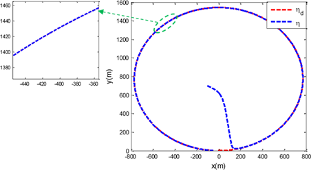
Figure 4 Reference path tracking by robot with proposed controller.
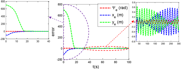
Figure 5 AUV path tracking error using the proposed controller in the presence of continuous sinusoidal disturbances.
In figure 6, the time and direction tracking error is shown and as it is clear, the convergence to zero has taken place. But from the comparison of the simulation results of two controllers in the second scenario, it can be concluded that the error in the proposed control, it is significantly less common than the sliding mode control.
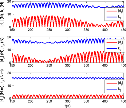
Figure 6 Control gain ((𝑡), nonlinear terms and disturbance in the proposed controller in the presence of continuous sinusoidal disturbances.
As shown in figure 7, the gain of the controller is estimated according to the amount of nonlinear terms, external disturbance and safety margin included in the control system.
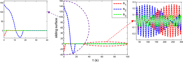
Figure 7 Slip surface in the proposed controller in the presence of disturbances.
A continuous sinusoid is shown in Figure 8 slip surfaces converge to zero.
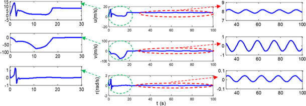
Figure 8 Linear and angular velocities of AUV using the proposed controller in the presence of continuous sinusoidal disturbances.
The linear and angular velocities are shown in figure 9. The range of velocities in the transient response is lower than in figure 9 and in the permanent response, although fluctuations are observed, the range of Fluctuations are relatively small.

Figure 9 Control effort of the proposed controller in the presence of continuous sinusoidal disturbances.
The control effort is shown in figure 9. Since the amplitude of disturbance is considered relatively high, the range of control forces and torques must also be close to these values to deal with the disturbance and also, Chattering is not observed in the control effort and it has a good quality. The range of the control effort in the transient response is less compared to the conventional sliding mode control. Therefore, the performance of the proposed controller is confirmed compared to the conventional sliding mode control in this scenario.
Conclusion
The simulation results of the proposed control and the conventional sliding mode control showed that in each of the hypothetical scenarios for the disturbance, the error rate in the proposed control is much lower than the conventional sliding mode control and the reference path tracking in the proposed resilient-adaptive control method is done more accurately. The amount of error was checked through soft, average and maximum indicators and all these indicators confirmed the performance of the proposed method compared to conventional sliding mode control. Also, the scope of the control effort in the conventional sliding mode control in the scenario had chattering, and in general the torque and control forces of the conventional sliding mode were more than the proposed control. If chattering was not observed in the proposed control and the range of control effort was appropriate. Therefore, in terms of the quality of the control effort, the performance of the proposed control is confirmed compared to the sliding mode control.
Acknowledgments
Conflicts of interest
Author declares that there is no conflict of interest.
References
- Paull L, Saeedi S, Seto M et al. AUV navigation and localization: A review. IEEE Journal of Oceanic Engineering. 2013;39(1):131–149.
- Borlaug Ida-Louise G, Kristin Y, Pettersen, et al. Comparison of two second-order sliding mode control algorithms for an articulated intervention AUV: Theory and experimental results. Ocean Engineering. 2021;222:108480.
- Cheng C, Sha Q, He B, et al. Path planning and obstacle avoidance for AUV: A review. Ocean Engineering. 2021;235(1):109355.
- Carroll KP, Mc Claran SR, Nelson EL, et al. AUV path planning: an A* approach to path planning with consideration of variable vehicle speeds and multiple, overlapping, time-dependent exclusion zones. Proceedings of the 1992 symposium on autonomous underwater vehicle technology. IEEE; 1992.
- Lapierre L, Bruno J. Robust nonlinear path-following control of an AUV. IEEE Journal of Oceanic Engineering. 2008;33(2):89-102.
- Wu Z, Peng H, Hu B, et al. Trajectory tracking of a novel underactuated AUV via nonsingular integral terminal sliding mode control. IEEE Access. 2021;9:103407–103418.
- Li D, Ling D. Auv trajectory tracking models and control strategies: A review. Journal of Marine Science and Engineering. 2021;9(9):1020.
- Zhang C, Cheng P, Du B, et al. AUV path tracking with real-time obstacle avoidance via reinforcement learning under adaptive constraints. Ocean Engineering. 2022;256:111453.
- Cao X, Hongbing S, Gene EJ. Multi-AUV cooperative target search and tracking in unknown underwater environment. Ocean Engineering. 2018;150(15):1–11.
- Sun Y, Ran X, Zhang G, et al. AUV 3D path planning based on the improved hierarchical deep Q network. Journal of Marine Science and Engineering. 2020;8(2):145.
- Chen F, Jiang R, Zhang K, et al. Robust backstepping sliding-mode control and observer-based fault estimation for a quadrotor UAV. IEEE Transactions on Industrial Electronics. 2016;63(8):5044–5056.
- Yu C, Xiang X, Lapierre L, et al. Robust magnetic tracking of subsea cable by AUV in the presence of sensor noise and ocean currents. IEEE Journal of Oceanic Engineering. 43(2):311–322.
- Elmokadem T, Mohamed Z, Kamal YT. Terminal sliding mode control for the trajectory tracking of underactuated autonomous underwater vehicles. Ocean Engineering. 2017;129:613–625.
- Jinyi Y, Quing J, Qiang Z, et al. Design and analysis of fully-actuated AUV's three-dimensional path tracking control system. Chinese Journal of Ship Research. 2019;14(6):22–29.
- Elmokadem T, Mohamed Z, Kamal YT. Trajectory tracking sliding mode control of underactuated AUVs. Nonlinear Dynamics. 2016;84(2):1079–1091.
- Labbadi, M, Mohamed C. Adaptive fractional-order nonsingular fast terminal sliding mode based robust tracking control of quadrotor UAV with Gaussian random disturbances and uncertainties. IEEE Transactions on Aerospace and Electronic Systems. 2021;57(4):2265–2277.

©2022 Jalalnezhada. This is an open access article distributed under the terms of the,
which
permits unrestricted use, distribution, and build upon your work non-commercially.


