
Conceptual Paper Volume 6 Issue 3
Active fault tolerant control based on nonlinear subject to actuator and sensor faults for a parallel robot
Mahmood Mazare,
Regret for the inconvenience: we are taking measures to prevent fraudulent form submissions by extractors and page crawlers. Please type the correct Captcha word to see email ID.

Mostafa Taghizadeh, Pegah Ghaf G
School of Mechanical engineering, Shahid Beheshti University, Iran
Correspondence: Mahmood Mazare, School of Mechanical engineering, Shahid Beheshti University, Iran, P.O.B. 1743524155, Tehran, Iran
Received: May 07, 2020 | Published: August 31, 2020
Citation: Mazare M, Taghizadeh M, Ghaf PG. Active fault tolerant control based on nonlinear H? subject to actuator and sensor faults for a parallel robot. Int Rob Auto J . 2020;6(3):115?125. DOI: 10.15406/iratj.2020.06.00210
Download PDF
Abstract
In this paper, an Active Fault Tolerant Control (AFTC) strategy using a nonlinear H∞ control is proposed for a delta type parallel robot in the presence of actuator and sensor fault. First, dynamic modeling of the robot is accomplished using the Lagrange method. To measure the position and velocity, a super-twisting third-order sliding mode (STW-TOSM) observer is applied. The proposed scheme can accommodate both faults and uncertainties without velocity measurement. In addition, fast convergence and high accuracy is achieved because of applying the high-order sliding mode (HOSM) observer. In order to indicate the effectiveness of the FTC on the basis of nonlinear H∞, its performance is compared with conventional sliding mode and feedback linearization methods. The obtained results reveal the efficacy of the proposed FTC- H∞.
Keywords: fault tolerant control, parallel robot, nonlinear H∞, finite time convergence
Introduction
Parallel manipulators have proven their outstanding performance compared to the conventional serial ones, in terms of high accuracy, velocity, stiffness, payload capacity and great dynamic performance.1,2 This makes them a good choice for application in industrial sector, particularly for processing and manufacturing, and increases the productivity and product quality. However, regardless of their satisfactory performance, they are prone to component faults and failures, which not only deteriorate their performance, but also has the potential to damage their structure and their environment. Moreover, effective handling the occurring faults can save considerable cost of repair and maintenance, and prevents the production line shutdown for every fault or minor failure. The growing demand for safety, reliability and productivity has been the driving force for the emergence of Fault-Tolerant Control (FTC) systems and has made them an indispensable part of control system design process.3 Successful implementation of this approach to various applications has proven its effectiveness in diverse fields like, spacecrafts,4,5 robotics,6-9 and energy.10–12
Generally, fault-tolerant control approaches can be categorized into two distinct categories: active approach,13,14 and passive approach.15,16 Passive FTC (PFTC) does not rely on the fault information, instead the effects of faults are considered as the effects of an additional uncertainties. In this case, a robust control approach is utilized to compensate for the effect of the faults.17,18 On the other hand, Active FTC (AFTC) requires the faults information in advance and is based on rearranging the control structure isolation.19,20
Fault detection (FD), a fundamental part of AFTC, is conducted through different approaches, among which sliding mode observer (SMO)21–23 is highly attractive, as it offers high robustness against uncertainties. However, conventional SMO suffers from chattering and infinite time convergence. The super-twisting SMO was designed to guarantee the finite time convergence of the state observer and attenuate the chattering,24–26 but it cannot eliminate it completely.27 High order Sliding Mode (HOSM) techniques have been proposed to promote accuracy and eliminate chattering, while retaining the robustness of the conventional SMC.28 A super-twisting third-order SMO gives both exact theoretical velocity estimations and an unknown input estimation.29 For FTC purpose of robotic manipulators, different strategies have been adopted, mainly based on computed torque control (CTC),30,31 backstepping,32 Neural Networks (NN),33 Model predictive,9 and sliding mode control (SMC).6,7
An adaptive fuzzy sliding mode controller with variable estimation was introduced by Piltan et al.34 to handle faults and uncertainties with high robustness, and verified with 6 DOF programmable universal manipulation arm (PUMA) 560 robot manipulator. The sliding surface slope gain of this sliding mode fault-tolerant control technique was tuned adaptively using a fuzzy procedure. Van et al.35 proposed a robust fault diagnosis and fault-tolerant control (FTC) system by applying a combination of a fault diagnosis scheme based on a super-twisting third-order sliding mode (STW-TOSM) observer with a robust super-twisting second-order sliding mode (STW-SOSM) controller to a PUMA560 robot. Employing high-order sliding mode (HOSM) observer/controller strategy has improved the convergence rate, enhanced the accuracy, and reduced the chattering. A finite-time integral back-stepping fault tolerant control for a class of nonlinear systems was introduced36 and applied to a two-link rigid robot manipulator. An adaptive version of the controller is then developed to deal with the total uncertainties in the system. It was proved that the controller is effective in terms of precision of tracking, convergent speed and robustness.
During recent years, nonlinear H∞ control theory has attracted increasing attention due to its inherent robustness and disturbance rejection capabilities and has been applied to a variety of systems, such as electric motors,37 spacecrafts,38–40 and robotic manipulators.41–43 The objective of this control theory is to achieve a bounded ratio between the energy of error signals and the energy of disturbance signals.44 To the best of the authors’ knowledge, nonlinear H∞ control scheme has not been employed for fault-tolerant control of robotic manipulators which takes actuator faults, input saturation, external disturbances and system uncertainties into account, simultaneously. Motivated by the above discussion, the most obvious contributions of this study can briefly be drawn as follows:
- Proposing a new finite-time FTC based on nonlinear H∞ and third order super twisting sliding mode observer for a delta type parallel robot which guarantees faster convergence of the system states and also provides high-precision tracking.
- Considering actuator and sensor faults, input saturation, external disturbances and parameter uncertainties simultaneously and applying a nonlinear robust FTC to deal with these challenges which can increase reliability and safety.
- The FTC-H∞ does not require uncertainty information, which enables the proposed FTC more applicable for implementing.
The following sections of this paper are: section 2 entailing the introduction of the 3[P2(US)] parallel robot, followed by its kinematic and dynamic analysis in sections 3 and 4. In section 5 the proposed control strategy is described and section 6 contains fault detection using STW-TOSM. Desired path planning is addressed in section 7. Section 8 is devoted to numerical simulation and the conclusion is drawn is section 9.
Architecture of 3[P2(US)] parallel manipulator
The 3[P2(US)] parallel manipulator under study consists of a moving platform termed the end-effector and a fixed platform named the base, joined together via three identical limbs as depicted in Figure 1. Each limb is comprised of an active prismatic joint, installed at an inclination relative to the base and a parallelogram linkage. As the name implies, each parallelogram consists of two parallel rods with universal and spherical joints at their both extremities.
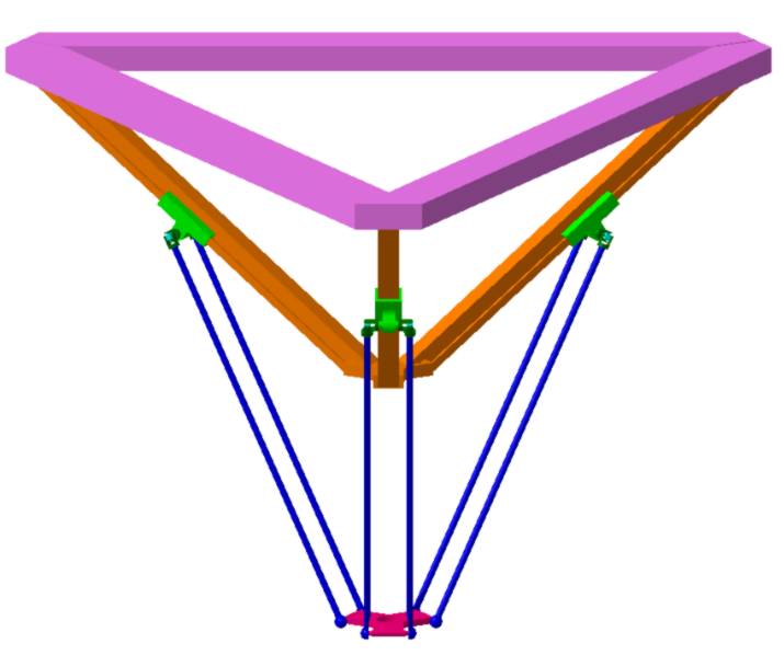
Figure 1 The 3[P2(US)] architecture of delta PKM.
Geometric parameters and variables of one of the limbs are illustrated Figure 2. Three limbs are connected to the base through points Ai, which are located on an imaginary circle with R radius and centered at the origin of reference frame. Similarly, the points Bi are placed on a circle with the radius r and show the connection between the limbs and the end-effector. Active prismatic joints are installed at the angle β to the base and are connected to the parallelogram via universal joints at the points Ci. The length of each parallelogram is specified with l.
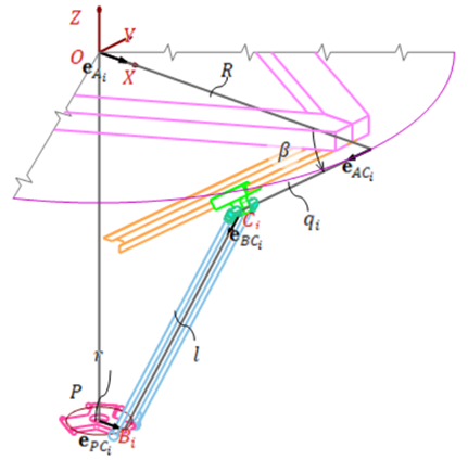
Figure 2 Parameters and variables of the i-th limb.
Kinematic model
By kinematic analysis, the relative displacement, velocity and acceleration of the links of the manipulator are derived. Jacobian matrix, which provides a mapping between the velocity of active joints and the velocity of the end-effector, is extracted in this section.
Looking at Figure 2, it is obvious that the magnitude of
, representing the length of i-th parallelogram, is constant, so
(1)
From the loop closure equation, we can write
(2)
(3)
where,
(4)
(5)
(6)
(7)
Replacing Eqs. (4–7) into Eq. 3 and simplifying the resulting equation yields the following constraint equation from which the forward and inverse kinematics of the PKM can be extracted.43
(8)
Direct differentiation of the kinematic Eq. 8 with respect to time yields the velocity equations.
(9)
where the Jacobian matrices are:
(10)
Considering the end-effector velocity vector as and the actuators velocity vector as
, the following linear mapping, known as forward velocity kinematic equation holds.
(11)
The Jacobians can also be derived directly from the following velocity equation.
(12)
Dot multiplying both sides of Eq. 12 with
omits the term including the unknown angular velocity of the parallelogram rods,
, and yields
(13)
which can be written in the matrix form of Eq. 9 where
(14)
(15)
Kinematic equations for acceleration can be derived by differentiation of Eq. 9 as:
(16)
Dynamic model
In order to analyze the dynamic behavior of the robot, Euler-Lagrange formulation is used. Since in parallel robots the generalized coordinates are constrained, the formulation comprising Lagrange multipliers is applied.
(17)
where is the j-th generalized coordinate, Qj is its corresponding generalized active force, λi s are the Lagrange multipliers, and fi are the constraint equations denoted by Eq 8. Generalized coordinates are defined as
(18)
Lagrangian is defined as the difference between kinetic and potential energies.
(19)
Due to the fact that rotational inertia of the parallelogram rods is negligible, they are considered as two point-masses on their both extreme ends. Thus, the kinetic energy of the whole manipulator will be calculated by adding the kinetic energy of the sliding actuators and that of the end-effector.
(20)
(21)
where
,
, and
represent the masses of the end-effector, the parallelogram, and the actuator piston, respectively. Potential energy of the whole mechanism is obtained from
(22)
Therefore, the Lagrangian of the system can be expanded as follows
(23)
Substituting the resulting Lagrangian into Eq. 17 and after some mathematical simplification, the resulting equations can be written in the following matrix form.45
(24)
Besides these three equations, three others are also needed to determine the six unknown generalized coordinates. These extra equations are the acceleration equations, Eq. (16)
(25)
The six equations of Eq. (24), (25) describe the dynamics of the robot. Eliminating
and
from these equations, the reduced dynamic equations are obtained as:
(26)
where,
(27)
In order to consider uncertainties and actuator faults, the dynamic model Eq. 26 can be rewritten as (30),
(28)
where
,
,
, and
are the fault vector, its time profile, the fault occurrence time, and uncertainties, respectively. The time profile of the fault is as follows:
(29)
where v denotes the growth rate of the fault. In this paper, actuator fault is taken into account which is one of the frequent failures in robotics. Small value or means that the fault is developing at slow rate, usually called an incipient fault. On the other hand, when this parameter has a large value, its time profile, γ, tends to a step function and is called an abrupt fault. Clearly, as v→∞, γ becomes a step function and the incipient fault turns to the abrupt fault. When an actuator fails, its force can be defined as:
(30)
The actuator fault,
, can be written as the fault function defined by
.
Now, the dynamic model of the robot can be rewritten as:
(31)
where N, Δ, and F introduce the nominal robot dynamics, uncertainties, and actuator faults, respectively.
Proposed control strategy
In this section, first of all, a nonlinear H∞ controller is designed to control a parallel robot in the presence of actuator faults, uncertainties and also exogenous disturbances.
The dynamic model of the parallel robot can be rewritten in the following state-space form:
(32)
where
. A performance index can be defined using the following cost variable:
(33)
where W is a weighting function and h(q) is a function of states which should be controlled. If the robot states are available, then the H∞ performance index is as follows (44):
(34)
in which
(35)
where Q and R are symmetric positive matrices. By relying on the
, then
. Therefore, the optimal control signal can be determined based on the solution of HJBI:46
(36)
For each
(maximum singular value). In this case, the optimal state feedback control command can be derived as:
(37)
By defining the tracking error vector
where
, and
. Due to acting persistence disturbances on the parallel robot during the whole process, the integral term is added to nullifying steady state error. Then, the following control law is taken into account:
(38)
where l is the nth-order identity matrix. By substituting the control command into the dynamic model, then the error dynamics can be expressed by the following expression:
(39)
By considering Eq. 39, we try to determine an optimal control signal so that
(40)
Based on the above vector error and cost variable ,
(41)
By rewriting the error dynamics into the standard form of the nonlinear H∞ problem as:
(42)
It should be noted that HJBI solution depends on the selection of both cost variable and h(q) which is considered equally to the error vector. By taking such function into account, a Lyapunov function should be chosen in order to determine the control law.
Theorem: Take the following Lyapunov function:
(43)
Where X,Y and Z are symmetric and positive definite matrices so that
by verifying the following expression, for the high value of γ, the candidate function embodies a solution of HJBI.
Some Riccati algebraic equations are solved to obtain
. By substituting the Lyapunov function in Eq.37, the control law can be rewritten as:
(44)
By replacing the control law in Eq. 0 and some mathematical simplification, the control law is as:
(45)
By defining
(46)
Now, the above gains can be rewritten as:
(47)
In which
and
are constant parameters. More details regarding stability analysis is presented in 43.
Remark: by considering the aforementioned control scheme, it can be obviously seen that should constant parameters obtain properly, stability of the closed-loop system in the presence of the exogenous disturbances, uncertainties and actuator faults will be guaranteed in finite time.
It is worth mentioning that the complex faults and disturbances are as follows. The fault is occurred at 1.5 sec.
(48)
(49)
As the controller performance is affected by actuator saturation, it is assumed that the maximum value of the control inputs is 100 N.m, in other words,
.
Fault detection based on a super-twisting third-order sliding mode observer
In this section, the observer scheme that is used for both state observer and fault diagnosis based on STW-TOSM observer is described. By defining
and
, the dynamic model Eq. can be rewritten in following form:
(50)
The third order super twisting sliding mode observer is as follows35
(51)
in which
are the sliding mode gains. By taking into account the estimation error as:
(52)
(53)
where
are the estimation error. By defining
(53)
and also by having the following assumptions:
(54)
then, a constant parameter is existing so that:
(55)
According to the analysis performed in,35 the sliding gains can be chosen as follows which ensure the stability and convergence of the system.
(56)
After converging the estimation error to zero, estimated states would be reached to actual stated and the following equality will be hold:
(57)
When the observer converges to zero, the third term of Eq. 57 is equal to zero. Then, uncertainty and fault can be reconstructed as:
(58)
Where
is a continuous term and low pass filter for determining equivalent output injection is not required.
Therefore, they are an exact estimation of the uncertainty and fault without filtration which could contribute the performance of AFTC due to requiring accurate fault estimation.
Path planning
The objective of optimal path planning is to design a path for the end-effector in an area containing some obstacles, so that it is of minimum length and avoids any collision with the obstacles. A predetermined margin is considered around the obstacles and the end-effector would keep a minimum distance from the borders of the obstacles.
To create a 2-D trajectory from the starting point,
, to the final point,
, in the time interval of
, a number of accuracy points are considered as:
(59)
Where Ti is the time instant at which the end-effector is planned to be located at Pi. All accuracy points will be checked to be placed in the reachable workspace and far enough from singular points. End-effector trajectory is derived by cubic spline interpolation of accuracy points coordinates Xi and Yi with respect to time that guarantees the continuity of velocity and acceleration. So, the trajectory curve can be obtained as,
(60)
Where, is the number of interpolated points along the curve. Spatial and time vectors are defined as,
(61)
Numerical simulation
To demonstrate effectiveness of the proposed fault-tolerant control scheme in performing trajectory tracking task in the presence of uncertainties, and actuator fault and saturation, some simulations have been performed. The desired path is formed by spline interpolation, passing through some accuracy points, and avoiding some obstacles in the workspace. System initial conditions are extracted from kinematic solution. To compare the performance of the proposed scheme with other methods, simulations are also conducted for feedback linearization and conventional sliding mode control schemes. Measurement noise is considered in this simulation. Control parameters are presented in Table 1.
|
Parameter
|
Value
|
|
ω1
|
0.5
|
|
ω2
|
8
|
|
ω3
|
5
|
|
ω4
|
0.12
|
Table 1 Controller parameters
Actuator trajectories and their errors are illustrated in Figure 3 and Figure 4 As can be seen from the results, the proposed controller is the most robust one compared to the other schemes, which upon occurring fault at 1.5 sec, it has maintained its high performance and followed the desired trajectories with minimum tracking errors. Moreover, finite time convergence is also evident in these figures. Figure 5 demonstrates how the desired trajectories in workspace have been followed by different controllers and how much error, and the corresponding errors have been presented in Figure 6. As can be seen, under the influence of actuator faults the tracking performance of the SM and FL controllers is declined significantly, while H∞ tracks the desired trajectories with high accuracy. Nullifying the influence of actuator fault and uncertainty would be the obvious fact with regards to superiority of the proposed H∞. The paths followed by the end effector under the influence of different controllers are illustrated in Figure 7. As is clear from the results, SM and FL controllers diverge from the desired path as the faults occur in the system. H∞, on the other hand, is capable of following the path with high precision. The control commands presented in Figure 8 reveal a reasonable range and fluctuation-free pattern of the signal. This has attained as a result of employing high-order algorithm. As the fault has occurred at 1.5 sec, the system has experienced a slight change.
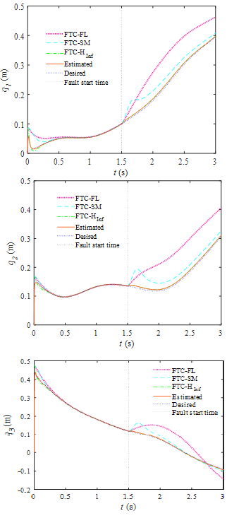
Figure 3 Actuator motion plots.
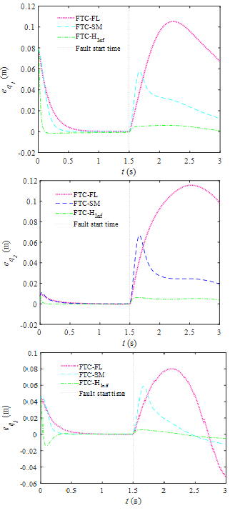
Figure 4 Tracking error components.

Figure 5 End-effector motion plots.
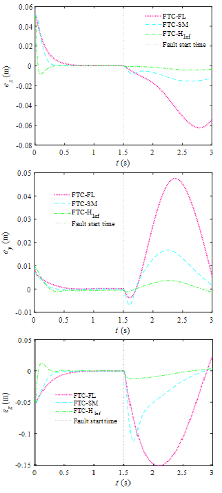
Figure 6 Tracking error components.
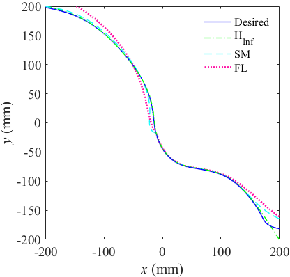
Figure 7 End-effector path following.
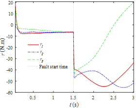
Figure 8 Actuator forces in the presence of actuator fault.
In order to show a vivid comparison between the three controllers, three error criteria termed as Integral of the Time multiplied by the Absolute value of the Error (ITAE), Integral of the Time multiplied by the Absolute value of the Squared of the Error (ITASE) and Integral of the Absolute value of the Error (IAE) have been studied, which are defined as,
(62)
Figure 9 Reveals that FTC on the basis of H∞ has the minimum value for the three criteria.
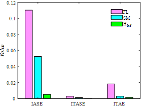
Figure 9 Error criteria in the presence of actuator fault.
To show the effectiveness of the TW-TOSM observer, the estimated velocity in joint space and workspace are compared with their actual values in Figure 10. As is clear from the result, this observer is able to estimate the velocities with high accuracy and no chattering. Fault detection performance of the H∞-based FTC is presented in Figure 11 through the obtained residuals from the simulations. As the fault occurs, the residuals cross the predefined threshold, showing the presence of the fault in the system.

Figure 10 Actual and estimated velocities.

Figure 11 Residuals of a faulty system under the effect of actuator fault.
Conclusion
In this paper, a robust Fault Tolerant Control based on nonlinear H∞ was proposed for a delta type parallel robot exposed to actuator fault. For fault detection a super-twisting third-order sliding mode (STW-TOSM) observer was exploited which can accommodate faults and uncertainties without velocity measurement. In addition, it provides fast convergence and high accuracy thanks to its high-order sliding mode algorithm. The simulation results proved that the proposed FTC offers high accuracy, finite time convergence for reasonable control effort compared to conventional SMC- and FL-based FTC schemes.
Funding
Acknowledgments
Conflicts of interest
The authors declare that there was no conflict of interest.
References
- Brinker J, Corves B, Takeda Y. Kinematic performance evaluation of high-speed Delta parallel robots based on motion/force transmission indices. Mechanism and Machine Theory. 2018;125:111–125.
- Guilin Y, Chen IM, Wei L, et al. Singularity analysis of three-legged parallel robots based on passive-joint velocities. IEEE Transactions on Robotics and Automation. 2001;17(4):413–422.
- Chen M, Tao G. Adaptive Fault-Tolerant Control of Uncertain Nonlinear Large-Scale Systems With Unknown Dead Zone. IEEE Transactions on Cybernetics. 2016;46(8):1851–1862.
- Hu Q, Shi Y, Shao X. Adaptive fault-tolerant attitude control for satellite reorientation under input saturation. Aerospace Science and Technology. 2018;78:171–182.
- Gao Z, Zhou Z, Qian MS, et al. Active fault tolerant control scheme for satellite attitude system subject to actuator time-varying faults. IET Control Theory & Applications. 2017;12(3):405–412.
- Meng Q, Zhang T, Gao X, et al. Adaptive Sliding Mode Fault-Tolerant Control of the Uncertain Stewart Platform Based on Offline Multibody Dynamics. IEEE/ASME Transactions on Mechatronics. 2014;19(3):882–894.
- Meng Q, Zhang T, He TF, et al. Adaptive vector sliding mode fault-tolerant control of the uncertain Stewart platform based on position measurements only. Robotica. 2016;34(6):1297–1321.
- Farid Y, Majd VJ, Ehsani-Seresht A. Fractional-order active fault-tolerant force-position controller design for the legged robots using saturated actuator with unknown bias and gain degradation. Mechanical Systems and Signal Processing. 2018;104:465–486.
- Karras GC, Fourlas GK. Model Predictive Fault Tolerant Control for Omni-directional Mobile Robots. Journal of Intelligent & Robotic Systems. 2020;97(3):635–655.
- Azizi A, Nourisola H, Shoja-Majidabad S. Fault tolerant control of wind turbines with an adaptive output feedback sliding mode controller. Renewable Energy. 2019;135:55–65.
- Lan J, Patton RJ, Zhu X. Fault-tolerant wind turbine pitch control using adaptive sliding mode estimation. Renewable Energy. 2018;116:219–231.
- Cho S, Gao Z, Moan T. Model-based fault detection, fault isolation and fault-tolerant control of a blade pitch system in floating wind turbines. Renewable Energy. 2018;120:306–321.
- Li B, Du H, Li W. Fault-tolerant control of electric vehicles with in-wheel motors using actuator-grouping sliding mode controllers. Mechanical Systems and Signal Processing. 2016;72-73:462–485.
- Jang JO. Neuro-fuzzy networks saturation compensation of DC motor systems. Mechatronics. 2009;19(4):529–534.
- Gao Z, Cecati C, Ding SX. A Survey of Fault Diagnosis and Fault-Tolerant Techniques—Part I: Fault Diagnosis With Model-Based and Signal-Based Approaches. IEEE Transactions on Industrial Electronics. 2015;62(6):3757–3767.
- Jiang J, Yu X. Fault-tolerant control systems: A comparative study between active and passive approaches. Annual Reviews in Control. 2012;36(1):60–72.
- Benosman M, Lum K. Passive Actuators' Fault-Tolerant Control for Affine Nonlinear Systems. IEEE Transactions on Control Systems Technology. 2010;18(1):152–163.
- Zhang R, Qiao J, Li T, et al. Robust fault-tolerant control for flexible spacecraft against partial actuator failures. Nonlinear Dynamics. 2014;76(3):1753–1760.
- Allerhand LI, Shaked U. Robust Switching-Based Fault Tolerant Control. IEEE Transactions on Automatic Control. 2015;60(8):2272–2276.
- Shen Q, Jiang B, Cocquempot V. Adaptive Fuzzy Observer-Based Active Fault-Tolerant Dynamic Surface Control for a Class of Nonlinear Systems With Actuator Faults. IEEE Transactions on Fuzzy Systems. 2014;22(2):338–349.
- Awan ZS, Ali K, Iqbal J, et al. Adaptive Backstepping Based Sensor and Actuator Fault Tolerant Control of a Manipulator. Journal of Electrical Engineering & Technology. 2019;14(6):2497–2504.
- Shi P, Liu M, Zhang L. Fault-Tolerant Sliding-Mode-Observer Synthesis of Markovian Jump Systems Using Quantized Measurements. IEEE Transactions on Industrial Electronics. 2015;62(9):5910–5918.
- Yin S, Yang H, Kaynak O. Sliding Mode Observer-Based FTC for Markovian Jump Systems With Actuator and Sensor Faults. IEEE Transactions on Automatic Control. 2017;62(7):3551–3558.
- Davila J, Fridman L, Levant A. Second-order sliding-mode observer for mechanical systems. IEEE Transactions on Automatic Control. 2005;50(11):1785–1789.
- Utkin V. On Convergence Time and Disturbance Rejection of Super-Twisting Control. IEEE Transactions on Automatic Control. 2013;58(8):2013–2017.
- Guzmán E, Moreno JA. Super-twisting observer for second-order systems with time-varying coefficient. IET Control Theory & Applications. 2014;9(4):553–562.
- Shtessel Y, Taleb M, Plestan F. A novel adaptive-gain super twisting sliding mode controller: Methodology and application. Automatica. 2012;48(5):759–769.
- Thanh HLNN, Hong SK. Quadcopter Robust Adaptive Second Order Sliding Mode Control Based on PID Sliding Surface. IEEE Access. 2018;6:66850–66860.
- KC Veluvolu, Van M, Franciosa P, et al. Fault Diagnosis and Fault-Tolerant Control of Uncertain Robot Manipulators Using High-Order Sliding Mode. Mathematical Problems in Engineering. 2016.
- Van M, Kang HJ, Suh YS, et al. A robust fault diagnosis and accommodation scheme for robot manipulators. International Journal of Control, Automation and Systems. 2013;11(2):377–388.
- Van M, Kang HJ, Suh YS. A novel neural second-order sliding mode observer for robust fault diagnosis in robot manipulators. International Journal of Precision Engineering and Manufacturing. 2013;14(3):397–406.
- Van M, Mavrovouniotis M, Ge SS. An Adaptive Backstepping Nonsingular Fast Terminal Sliding Mode Control for Robust Fault Tolerant Control of Robot Manipulators. IEEE Transactions on Systems, Man, and Cybernetics: Systems. 2019;49(7):1448–1458.
- Van M, Kang HJ. Robust fault-tolerant control for uncertain robot manipulators based on adaptive quasi-continuous high-order sliding mode and neural network. Proceedings of the Institution of Mechanical Engineers, Part C: Journal of Mechanical Engineering Science. 2015;229(8):1425–1446.
- Piltan F, Kim H, Kim JM. Advanced Adaptive Fault Diagnosis and Tolerant Control for Robot Manipulators. Energies. 2019;12(7).
- Van M, Franciosa P, Ceglarek D. Fault Diagnosis and Fault-Tolerant Control of Uncertain Robot Manipulators Using High-Order Sliding Mode. Mathematical Problems in Engineering. 2016:7926280.
- Smaeilzadeh SM, Golestani M. Finite-time fault-tolerant adaptive robust control for a class of uncertain non-linear systems with saturation constraints using integral back stepping approach. IET Control Theory & Applications. 2018;12(15):2109–2117.
- Rigatos G, Siano P, Wira P, et al. Nonlinear H_∞ Feedback Control for Asynchronous Motors of Electric Trains. Intelligent Industrial Systems. 2015;1(2):85–98.
- Raffo GV, Ortega MG, Rubio FR. Path Tracking of a UAV via an Underactuated H [infinity] Control Strategy. European Journal of Control. 2011;2:194–213.
- Han C, Guo J, Pechev A. Nonlinear H∞ based underactuated attitude control for small satellites with two reaction wheels. Acta Astronautica. 2014;104(1):159–172.
- Raffo GV, Ortega MG, Rubio FR. An integral predictive/nonlinear H∞ control structure for a quadrotor helicopter. Automatica. 2010;46(1):29–39.
- Rigatos G, Siano P, Abbaszadeh M. Nonlinear H_∞ control for 4-DOF underactuated overhead cranes. Transactions of the Institute of Measurement and Control. 2018;40(7):2364–2377.
- Rigatos G, Siano P, Raffo G. A nonlinear H_∞ control method for multi-DOF robotic manipulators. Nonlinear Dynamics. 2017;88(1):329–348.
- Ortega MG, Vargas M, Vivas C, et al. Robustness improvement of a nonlinear H∞ controller for robot manipulators via saturation functions. Journal of Robotic Systems. 2005;22(8):421–437.
- Van der Schaft A. L/ Sub 2/-gain analysis of nonlinear systems and nonlinear state feedback H/ sub infinity/control. Transactions on Automatic Control. 1992;37(6):770–784.
- Mazare M, Taghizadeh M, Najafi MR. Contouring control of a 3-[P2(US)] parallel manipulator. Advanced Robotics. 2017;31(9):496–508.
- Van der Schaft A. L2-gain and passivity techniques in nonlinear control. New York: Springer-Verlag; 2000.

©2020 Mazare, et al. This is an open access article distributed under the terms of the,
which
permits unrestricted use, distribution, and build upon your work non-commercially.


