International Journal of
eISSN: 2576-4454


Case Report Volume 3 Issue 3
Hydraulic Department, Intertechne Consultores Associados SA, Brazil
Correspondence: Claudia Trevisol Dalmora, Intertechne Consultores Associados, Hydraulic Department, Avenida Iguaçu-100, Curitiba, Paraná, Brazil, Tel +55(41)32197200, Tel +55(41)32197200
Received: May 17, 2019 | Published: June 6, 2019
Citation: Dalmora CT, Grube R. The first filling of the Laúca hydroelectric power plant reservoir. Int J Hydro. 2019;3(3):217-223. DOI: 10.15406/ijh.2019.03.00183
The Laúca hydroelectric power plant (2070MW) has been constructed on the Kwanza river in Angola. The general layout of the power plant comprises a concrete dam on the riverbed, in which are located the bottom outlet, the spillway and the intake structure of the ecological powerhouse. Near the dam, in the same alignment, around the right bank of the river, is located the intake structure of the main powerhouse. The ecological powerhouse, with one Francis turbine, is located immediately downstream of the dam. The project has an underground main powerhouse with six Francis turbines and six underground hydraulic circuits (one for each unit). To allow the construction of the dam, two diversion tunnels were constructed on the right bank and operated during two and a half years, from September 2014 to March 2017 when the process of filling the reservoir started. The reservoir filling occurred from the water level around 730.00m to the normal water level of the reservoir which is 850.00m, lasted about 1 year and 3 months (from March 2017 to June 2018) and was successfully completed. The present paper describes and shows the main aspects and information related to the first filling of the Laúca HPP reservoir.
Keywords: reservoir filling, hydroelectric power plant, river diversion, diversion tunnel closure, bottom outlet, spillway.
The reservoir filling is an important activity that is part of the final phase of a hydroelectric power plant construction. This activity usually includes the closure of the river diversion scheme, the beginning of the operation of the discharge structures and also the beginning of the operation of the powerhouse. Once this task has been successfully completed, it is possible to start the power generation in a hydroelectric power plant. Therefore, in general, this is the reason that justifies the relevance and importance of this theme. The main objective of this article is to report the aspects and information of the reservoir filling process of the Laúca hydroelectric power plant (HPP).
The Laúca hydroelectric power plant has been constructed on the Kwanza River in Angola, its location in the country is illustrated in Figure 1. The hydroelectric, owned by GAMEK - Gabinete de Aproveitamento do Médio Kwanza, was constructed by Odebrecht Engenharia & Construção, which hired Intertechne Consultores Associados as designer and its operation started in July 2017. To generate the 2070MW, the project comprises an ecological powerhouse, provided with one Francis unit (70MW), located immediately downstream of the dam and an underground main powerhouse, provided with six Francis units (333.33MW unit power). Each unit is supplied by an individual underground power tunnel (10.3m diameter and around 2000m long each), which connects the powerhouse with an intake near the dam. The concrete dam is nearly 130m high and nearly 1200m wide. The spillway, the bottom outlet and the intake structure of the ecological powerhouse are situated on the central portion of the dam. In order to build the dam, the Kwanza river was diverted through two diversion tunnels excavated in the right bank of the Kwanza river. Figure 2 presents the main structures of the HPP. The river bed at dam site situates around elevation 720.00 m and the normal water level of the reservoir is 850.00m.
The diversion of the Kwanza River to allow the construction of the Laúca hidroelectric power plant took place in two-stages. The first stage comprised the construction of a rock-earth cofferdam on the right bank to provide condition for the tunnels and the intake structures to be constructed. During this stage the Kwanza River kept its natural course and was only partially obstructed by the cofferdam. During the second stage, after the tunnels have been finalized and the Kwanza River has been diverted from its natural channel through the tunnels, upstream and downstream cofferdams have been built to allow the construction of the dam in the riverbed. This situation is presented in the Figure 3. The diversion tunnels were designed to safely discharge the 50 years flood (annual period), meaning a peak flow of 4337m³/s. Both diversion tunnels have an arc rectangular section with 14m high and 14m wide. The most external tunnel is named tunnel 2 with a total length of around 568m, while tunnel 1 is around 463m long. The tunnels were excavated in sound rock and, due to the good rock quality, they remained unlined. At the tunnel’s entrances, concrete structures with steel gates have been built to allow, at the end of the construction, the closure of the diversion tunnels and the start of the reservoir filling.
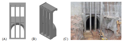
The intake structure of tunnel 1 was provided with three steel gates 3.9m wide and 16.5m high with sill at elevation 723.00m (Figure 4). Tunnel 1 was designed to be plugged prior to reservoir impoundment (while tunnel 2 was still open) so, the structure was designed to support the loads during this diversion phase (water level near elevation 755.00m). The intake structure of tunnel 2 was provided with three steel gates 3.9m wide and 14.0 m high (Figure 5). Since this structure was used to initiate the reservoir impoundment, it was designed to support the load of the full reservoir, leading to a more robust structure when compared to the one designed for tunnel 1. The Figure 3 shows both tunnels operating during the dam construction phase.

Figure 4 Inlet structure of the diversion tunnel 1. Figures (A) and (B) correspond to the design of the structure and figure (C) shows this structure during its construction phase.

Figure 5 Inlet structure of the diversion tunnel 2. Figures (A) and (B) correspond to the design of the structure and figure (C) shows this structure during its construction phase.
At the final construction stages, tunnel 1 was plugged, remaining only tunnel 2 opened. In this situation all the flow was discharged by tunnel 2, increasing flow velocities in the structure. So, to prevent cavitation, the hydraulic surface at the tunnel 2 entrance was rounded. Since tunnel 1 was not subjected to very high velocities, a chamfered transition was adopted at its entrance. All stages of the river diversion work operated successfully from September 2014, when the Kwanza River was diverted to the tunnels, to March 2017 when the intake structure of tunnel 2 was closed to start the reservoir filling. The inflow, outflow and the reservoir water level during the operation of both diversion tunnels are shown in the Figure 6. During this period, the maximum discharge was 1863m³/s (43% of the design flow), which is close to the 2 years flood (annual period). For this maximum discharge the flow velocities at the exit channel (end of tunnels) reached nearly 12m/s and the flow inside the tunnels were free surface type (not pressurized). The inspection of the tunnels, after the tunnels closure, showed that both tunnels performed well and no significant damage occurred due to the flow velocities.
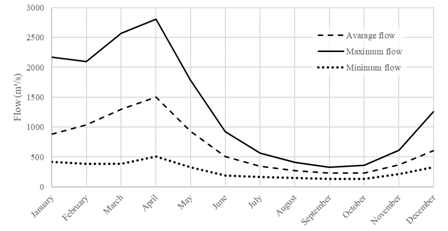
The closure of the diversion tunnels and the reservoir filling of the Laúca hydroelectric power plant was carried out according to schedule program of the works and the hydrological regime of the Kwanza River, that is, dry period and wet period. The hydrological regime of the river Kwanza occurs in such a way that the driest months are the months of June to November and the wet months are those of December to May. The Figure 7 shows the average, maximum and minimum flows at the Laúca HPP based on the monthly average flow data from 1951 to 1974. Therefore, since the intake structure of the tunnel 1 was not designed to withstand high loads, its closure should occur in the dry period. In general, this means that this tunnel should be closed and plugged in the dry period so that its inlet concrete structure was not subjected to high loads. The diversion tunnel 2 should be closed immediately before, or at the beginning, of the wet period to allow the impoundment of the reservoir with high river flows.

Figure 7 Monthly average flow at the Laúca HPP (Source : Intertechne Consultores Associados S.A., 2012 to 2018).
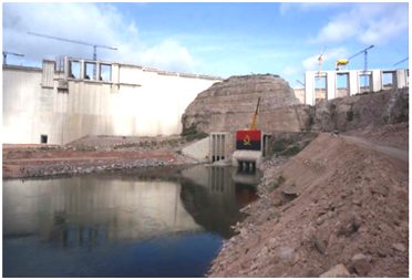
Both diversion tunnels operated simultaneously until October 2016, when the tunnel 1 was closed on October 8th, 2016. The flow through the Kwanza River on that moment was approximately 375m³/s. In sequence, the plug construction inside of the tunnel 1 was started and concluded successfully. The tunnel 1 closure sequence is shown in the Figure 8. The diversion tunnel 2 was successfully closed on March 11th, 2017, starting the reservoir filling. Figure 9 illustrates an upstream view of the reservoir after the closure of the tunnel 2 (the tunnel 1 was already closed). At that moment, the dam was not completely finished and the spillway’s mechanical equipment (gates) were not fully operational yet. The decision to initiate the impoundment, without the completion of these structures, was assisted by hydrological studies based on routing simulations of synthetic series of daily flows data. An unusual wet season could eventually impound the reservoir too fast and could cause the dam overtopping. When the diversion tunnels were closed the dam construction had not been concluded yet and these studies allowed the evaluation of the risk during this phase of the construction.1

Figure 8 Closure sequence of tunnel diversion 1. (A) The closure of the first gate of the inlet structure; (B) The closure of the last gate of the inlet structure. (C) The conclusion of the closure.

Figure 9 Upstream view of the diversion tunnels 1 and 2 after the closure of the tunnel 2. March 11th, 2017 (Source: Intertechne Consultores Associados S.A., 2017).
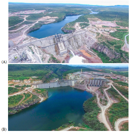
The Figure 10 shows the reservoir water level during the filling process which had been initiated with the closure of the diversion tunnels. This figure also shows the inflow at the reservoir during the reservoir filling from the water level around 730.00m to the water level 850.00m, which is the normal water level of the Laúca HPP. The same figure presents also important events during the reservoir filling, such as: the closure of both diversion tunnels, the start of the operation of the first unit of the main powerhouse, the first operation of the bottom outlet and the first operation of the spillway. During the initial stages of the impoundment, the ecological flow was released by valves located at the steel gates of the diversion tunnel 2. Then, as soon as the water level in the reservoir reached the bottom outlet, the ecological flow was maintained by this structure. The moment of the first operation of the bottom outlet, on 11th March, 2017, was registered according to the picture shown in the Figure 11. With the rise of the reservoir water level, the flow discharged by the bottom outlet also increased as schematically exposed in the Figure -14. The Figure 12 shows an upstream view of the dam on March 17th, 2017 and the bottom outlet discharging around 260m³/s on the same date.

Figure 11 The first operation of the bottom outlet during the reservoir filling. a) Upstream view of the bottom outlet entrance. b) Downstream view of the bottom outlet. March 11th, 2017.

Figure 12 Reservoir filling process. (A) Downstream view of the bottom outlet operation. (B) Upstream view of the reservoir filling process. March 17th, 2018.
The graphic of the Figure 14 shows the reservoir water level, the inflow in the reservoir and the outflow through the bottom outlet, the spillway and the main powerhouse of the Laúca HPP. The minimum operational water level of the HPP, elevation 800.00m, was reached on April 25th, 2017. The Figure 13 illustrates the reservoir almost reaching the elevation of the spillway crest (830.00m) during the reservoir filling process. On April 20th, 2018 occurred the first operation of the spillway of the Laúca HPP (Figure 15). In the first days of June of the year 2018, the reservoir of the Laúca HPP reached the elevation 850.00m which is the normal water level of the reservoir. This was an important milestone of the project and it is possible to say, at the end of this important stage, that is the reservoir filling, that the whole process occurred well, without major intercurrences. The picture of the Figure 16 shows an upstream view of the reservoir after the conclusion of the reservoir filling process.2‒5
Paper written with the support and authorization of GAMEK - Gabinete de Aproveitamento do Médio Kwanza and Odebrecht Engenharia & Construção.
The authors declare that there is no conflict of interest.

©2019 Dalmora, et al. This is an open access article distributed under the terms of the, which permits unrestricted use, distribution, and build upon your work non-commercially.