Research Article Volume 2 Issue 2
Research on the free vibrational characteristics of isotropic coupled conical-cylindrical shells
Chuang Wu1,2
Regret for the inconvenience: we are taking measures to prevent fraudulent form submissions by extractors and page crawlers. Please type the correct Captcha word to see email ID.

1State Key Laboratory of Mechanical System and Vibration, Shanghai Jiao Tong University, China
2Institute of Vibration Shock and Noise, Shanghai Jiao Tong University, China
Correspondence: Chuang Wu, State Key Laboratory of Mechanical System and Vibration, Institute of Vibration Shock and Noise, Shanghai Jiao Tong University, Shanghai, 200240, China
Received: February 05, 2018 | Published: March 7, 2018
Citation: Wu C. Research on the free vibrational characteristics of isotropic coupled conical-cylindrical shells. Aeron Aero Open Access J. 2018;2(2):39-46. DOI: 10.15406/aaoaj.2018.02.00027
Download PDF
Abstract
Based on the transfer matrix theory and precise integration method, the precise integration transfer matrix method (PITMM) is implemented to investigate the free vibrational characteristics of isotropic coupled conical-cylindrical shells. The influence on the boundary conditions, the shell thickness and the semi-vertex conical angle on the vibrational characteristics are discussed. Based on the Flugge thin shell theory and the transfer matrix method, the field transfer matrix of cylindrical and conical shells is obtained. Taking continuity conditions at the junction of the coupled conical-cylindrical shell into consideration, the field transfer matrix of the coupled shell is constructed. According to the boundary conditions at the ends of the coupled shell, the natural frequencies of the coupled shell are solved by the precise integration method. An approach for studying the free vibrational characteristics of isotropic coupled conical-cylindrical shells is obtained.
Keywords: coupled conical-cylindrical shells, precise integration, transfer matrix, vibration, natural frequency
Introduction
In engineering applications, especially in the field of modern military defence, the cylindrical shells, conical shells and coupled conical-cylindrical shells are basically simplified models of many types of weapons and equipment, such as aircraft, missiles, and submarines. The study of free vibrational characteristics of cylindrical shells is comprehensive. Initially, researchers1-5 investigated cylindrical shells using classic thin shell theories such as Donnell equations, Kennard equations, Flugge equations and Sander-Koiter equations. Harari, Sandman and Laulagnet were representative scholars in the field. Rayleigh6 was a pioneer in the study of free vibrational characteristics of cylindrical shells. The literary work of Leissa7 gave general comments on the free vibrational characteristics of cylindrical shells. The free vibrational characteristics of conical shells with simply-supported boundary conditions are examined using Statistical Energy Analysis by Creenwelge.8 Talebitooti9 and Li10 analysed the free vibrational characteristics of conical shells using the Rayleigh-Ritz method. The kp-Ritz method is used to study conical shells in the work of Liew et al.11 Guo12 applied the multiple factor method to discuss the free vibration characteristics of conical shells.
Unlike the cylindrical shells, the section radius of a conical shell will vary in the axial direction, which increases the complexity and the difficulty in studying conical shells. So far, only an approximate solution for determining the natural frequencies of conical shells has been obtained. Limited work on the analysis of free vibrational characteristics of coupled conical-cylindrical shells has been carried out. Initially, the natural frequencies of the coupled conical-cylindrical shell were solved used FEM. Irie13 investigates the natural frequencies of the coupled shell through the transfer matrix theory. Caresta14 used the two thin theories by Donnell-Mushtari and Flugge to examine the free vibrational characteristics of coupled shells. This paper applies a new method to analyse the free vibrational characteristics of isotropic coupled conical-cylindrical shells, which is different from the approach employed in previous studies. The method is referred to as PITMM. Based on the Flugge thin shell theory, equations of motion for cylindrical and conical shells are derived. The coefficient matrix in the equations of motion for cylindrical and conical shells is calculated using the precise integration method. To take into account the point transfer matrix at the junction of the coupled conical-cylindrical shell and to absorb the matrix assembly solution from FEM, the total transfer matrix of the coupled shell is constructed. According to the boundary conditions, the natural frequencies of the coupled shell are solved.
Equations of motion
Motion of a cylindrical shell
The shell deformation is described by the thin shell theory that is based on linear assumptions. To obtain precise results, the relatively accurate Flugge shell theory is used in this paper. The force balance equation is obtained by analysing the micro-element stress of the cylindrical shell. In this paper, the equations are based on the kinetic theory. Thus, many terms include time items. For the purpose of facilitating the writing and derivation, the dynamic response time item
is omitted in the remainder of the text. The cylindrical shell coordinates system
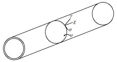
and displacement positive direction are shown in Figure 1.
Based on the Flugge shell theory, the force balance equation of a cylindrical shell is given as follows:
(1)
(2)
(3)
(4)
(5)
The Kevin-Kirchhoff membrane forces, shear and all internal forces are
(6)
(7)
(8)
(9)
(10)
(11)
(12)
(13)
(14)
(15)
where
and
are the bending rigidity and membrane rigidity, respectively.
(16)
(17)
The relationship between the radial displacement and slope is
(18)
There are sixteen unknown quantities in the above equations. To eliminate eight unknown quantities
, eight unknown quantities
are retained, which are the sectional state vector elements of the cylindrical shell. All quantities are processed into dimensionless quantities and expanded to trigonometric series along the circumferential direction.
(19)
(20)
(21)
(22)
(23)
(24)
(25)
where n is the circumferential modal number. Other dimensionless quantities and dimensionless frequency parameter are
(26)
(27)
(28)
(29)
Through complicated simplification, a first-order matrix differential equation of the cylindrical shell is obtained.
(30)
where
is the state vector of the cylindrical shell.
are the dimensionless quantities of the axial displacement (
direction), the circumferential displacement (
direction) and the radial displacement (
direction), respectively.
is a dimensionless slope,
is a dimensionless membrane force,
is a dimensionless bending moment,
are the dimensionless Kelvin-Kirchhoff shear force and shear force,
and
are Young’s modulus and Poisson’s ratio, respectively.
is the shell element’s state vector and is also a function of the dimensionless variables
.
is the coefficient matrix of the differential equation of the cylindrical shell and is an eight-order square matrix. There are 22 non-zero elements in
, see Appendix A.
Motion of the conical shell
In a cylindrical coordinate system, the generatrix direction and radial direction of the conical shell are defined as the coordinate direction. The position of any point on a conical shell can be described as
.
is length from the top point of the conical shell to any point on the conical shell along the generatrix direction.
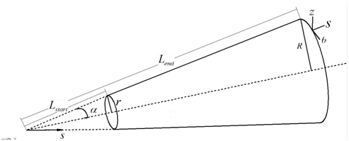
is the angle of the point along the circumferential direction in a cylindrical coordinate system. The coordinate system of a conical shell is seen in Figure 2. The analysis of the conical shell force, the force balance equation of a conical shell is given as follows:
(31)
(32)
(33)
The Kevin-Kirchhoff membrane forces, shear and all internal forces are
(34)
(35)
(36)
(37)
(38)
(39)
(40)
(41)
(42)
The relationship between radial displacement and the slope of conical shell satisfies
(43)
All quantities are processed into dimensionless quantities and expanded to trigonometric series along the circumferential direction.
(44)
(45)
(46)
(47)
(48)
(49)
(50)
where bending rigidity is
, Young’s modulus and Poisson’s ratio are
and
, respectively.
is the circumferential modal number.
and
are the symmetric or the anti-symmetric modal, respectively.
is the radius at the larger end of the conical shell.
is the thickness of the conical shell. Other dimensionless quantities are presented as
(51)
(52)
(53)
(54)
(55)
,
,
are described in \.
,
,
are, respectively, material density, circular frequency and the dimensionless frequency parameter. There are sixteen unknown quantities in the above equations. To eliminate eight unknown quantities
, eight unknown quantities
are retained, which are the sectional state vector elements of the conical shell. Then, the first-order matrix differential equation of the conical shell is obtained.
where
is the state vector of the conical shell.
is the variable coefficient matrix,
are exciting loads. The non-zero elements inare shown in Appendix B.

Figure 1 Coordinate system of a cylindrical shell.

Figure 2 Coordinate system of the conical shell
Solutions to equations
Assuming that the exciting loads of Eqs. (30), (56) are zero, the equations of motion are simplified to
(57)
(58)
Eqs. (57) and (58) are the equations of motion for the cylindrical and conical shell, respectively, which are dealt with as follows
(59)
(60)
(61)
(62)
(63)
In the following chapters, the solution for the coefficient matrix
using the precise integration method is presented.
Solutions for the coefficient matrix of the cylindrical shell
In the numerical calculation, the cylindrical shell is divided into a series of segments. The node coordinate of a segment is
,
=i+1,i+2,i+3,…. Any coordinates of contiguous nodes are
and
, where
. The coefficient matrix
for the cylindrical shell is independent of
. Thus, the coefficient matrix in Eq. (63) can be written as
(64)
Assuming that
(65)
where
, and a value of 20 is recommended for
.
can be expressed in terms of the Taylor series by
(66)
where
is an eight-order unit matrix. Using the addition theorem directly to add
and
when
is small relative to
, an error in the mantissa will occur due to computer rounding errors and leads to loss of precision.
Therefore, this paper uses an addition theorem to calculate
(67)
<
can be assumed as
(68)
After the
circulating assignment of Eq. (68), Eq. (67) can be written as
(69)
Assuming segment coefficient matrix
, the relationship of the state vector of each node can be described as
(70)
(71)
(72)
(73)
Solutions for the coefficient matrix of the conical shell
To facilitate the numerical calculation, the conical shell is split into a series of segments along the generatrix direction. Eq. (63) can be written as
(74)
(75)
(76)
(77)
Assuming
(78)
Eqs. (75)-(78) can be described as
(79)
(80)
(81)
(82)
The coefficient matrix
for the conical shell is dependent on
. Therefore, the transfer matrix
cannot be calculated like the transfer matrix for a cylindrical shell. This paper calculates the transfer matrix
for a conical shell by precise integration. Segments
of the conical shell are divided into a precise integral step
A value of 5 is recommended for
. For the segment
of the conical shell, the integral step node is
,
. In a precise integral step, assuming
,
can be recognized to be the constant coefficient matrix, which is independent of
. The variable coefficient matrix
in segment
of the conical shell can be calculated through the constant coefficient matrix of integral steps tiered multiplication
(83)
The constant coefficient matrix
of the precise integral step can be solved like the reference method for solving
in section 3.1.
Solutions for the point matrix at the junction of the coupled shell
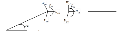
The displacements, slopes, forces and moments at the junction of the coupled conical-cylindrical shell should satisfy the following deformation compatibility conditions (Figure 3) (Figure 4).
a. At the junction of the coupled shell, the displacements and slopes
of the conical shell are in continuity with
of the cylindrical shell at the three coordinate axis.
b. At the junction of the coupled shell, the forces and moments
of the conical shell are equal to
of the cylindrical shell at the three coordinate axis.
According to the positive directions shown in the Figure 3 and Figure 4, the displacements, slopes, forces and moments of the conical and cylindrical shells at the junction satisfy
(84)
(85)
(86)
(87)
(88)
(89)
(90)
(91)
To take into consideration displacements, slopes, forces and moments satisfying the continuity conditions at the junction, the relationship of the left end state vector and the right end state vector at the junction is
(92)
Eq. (92) can be written as
(93)
The point transfer matrix
can be described as
(94)
Solutions for the coefficient matrix of the coupled shell
An illustration of the coupled conical-cylindrical shell is seen in Figure 5,
where is the semi-vertex conical angle.
is the radius of the cylindrical shell, which is also the larger end radius of the conical shell.
is the length from the top point of the conical shell to the smaller end of conical shell along the generatrix direction.
is the length from the top point of the conical shell to the larger end of the conical shell along the generatrix direction. The length of conical shell is
and the length of the cylindrical shell is
. The thickness of the coupled shell is
.
According to sections 3.1, 3.2, and 3.3, the state vector of the segment nodes from the coupled conical-cylindrical shell satisfy
(95)
(96)
(97)
(98)
(99)
(100)
Eqs. (95)-(100) can be written in term of a matrix as follows
(101)
According to the given boundary conditions at the ends of the coupled shell, row numbers where elements of the state vector are zero are found. Then, to delete corresponding columns of coefficient matrix, Eq. (101) can be written as
(102)
Since the state vectors cannot all be zero vectors, the determinant of the coefficient matrix must be zero. The following equation is obtained.
(103)
The natural frequencyof the coupled conical-cylindrical shell is the only unknown quantity in the matrix
and is obtained through solving the frequency characteristic Eq. (103). By substituting the natural frequency into Eq. (102), the proportional relationship of state vectors can be obtained. Then, the modes of the coupled shell will be acquired in the given boundary condition.

Figure 3 The positive directions for displacements and slopes of conical and cylindrical shells.

Figure 4 The positive directions for forces and moments of conical and cylindrical shells.

Figure 5 Illustration for the coupled conical-cylindrical shell.
Conclusion
A new method, PITMM, is introduced in this paper to research the free vibrational characteristics of isotropic coupled conical-cylindrical shells. Based on the traditional transfer matrix and precise integration methods, the PITMM is constructed. The method not only retains the traditional transfer matrix methods’ advantages of formula regularity and easy programming but also obtains the high accuracy from the precise integration methods.
Acknowledgement
The authors gratefully acknowledge the financial support from the National Natural Science Foundation China (No.51209052).
Conflicts of Interest
References
- Harari A. Wave propagation in cylindrical shells with finite regions of structural discontinuity. J Acoustic Soc Am. 1977;62(5):1196‒1205.
- Harari A. Wave propagation in a cylindrical shell with joint discontinuity. Shock and Vibration. 1978;48:52‒61.
- Harari A, Sandman BE. Radiation and vibrational properties of submerged stiffened cylindrical shells. J Acoust Soc Am. 1990;88(4):1817‒1830.
- Sandman BE. Fluid-loaded influence coefficients for a finite cylindrical shell. J Acoust Soc Am. 1976;60(6):1256‒1264.
- Koutunvov VB. Dynamic stability and nonlinear parametric vibration of cylindrical shells. Comput Struct. 1993;46(1):149‒56.
- Rayleigh J. The theory of Sound. New York: Dover Publication; 1945.
- Leissa AW. Vibration of Shells. National Aeronautics and Space Administration: Washington; 1973. pp. 438.
- Greenwelge OE, Muster D. Free vibrations of ring-and-stringer-stiffened conical shells. J Acoust Soc Am. 1969;46(1):176‒185.
- Talebitooti M, Ghayour M, Ziaei Rad S, et al. Free vibrations of rotating composite conical shells with stringer and ring stiffeners. Archive of Applied Mechanics. 2010;80(3):201‒215.
- Li FM, Kishimoto K, Huang WH. The calculations of natural frequencies and forced vibration responses of conical shell using the rayleigh-ritz method. Mechanics Research Communications. 2009;36(5):595‒602.
- Liew KM, Ng TY, Zhao X. Free vibration analysis of conical shells via the element-free kp-ritz method. Journal of Sound and Vibration. 2005;281(3-5):627‒645.
- Guo YP. Normal mode propagation on conical shells. J Acoust Soc Am. 1994;96(1):256‒264.
- Irie T, Yamada G, Muramoto Y. Free vibration of joined conical-cylindrical shells. Journal of Sound and Vibration. 1994;95(l): 31‒39.
- Caresta M, Kessissoglou NJ. Free vibrational characteristics of isotropic coupled cylindrical–conical shells. Journal of Sound and Vibration. 2010;329(6):733‒751.

©2018 Wu. This is an open access article distributed under the terms of the,
which
permits unrestricted use, distribution, and build upon your work non-commercially.


