Submit manuscript...
eISSN: 2576-4500

Aeronautics and Aerospace Open Access Journal

Review Article Volume 3 Issue 1

Analysis of tolerances and thermo-mechanical strains by operations on polytopes for hyperstatic mechanism architecture

Denis Teissandier,1 Yann Ledoux,1 Laurent Pierre2

1Univ. Bordeaux, I2M, UMR 5295, F-33400 Talence, France
2ENS Paris-Saclay, Lurpa, France

Correspondence: Yann Ledoux, Univ. Bordeaux, I2M, UMR 5295, F-33400 Talence, France, Tel 33-5 5684 6393

Received: February 27, 2019 | Published: March 29, 2019

Citation: Teissandier D, Ledoux Y, Pierre L. Analysis of tolerances and thermo-mechanical strains by operations on polytopes for hyperstatic mechanism architecture. Aeron Aero Open Access J. 2019;3(1):24-38. DOI: 10.15406/aaoaj.2019.03.00078

Download PDF

Keywords

hyperstatic mechanism, geometric tolerancing, thermo-mechanics, polytope

Introduction

The development of new manufacturing methods and the revolution in the production system enable the design of innovative systems with high-performance and most of time complex geometries and architectures (i.e. high-efficiency engines, lightweight aircraft structures, etc.). This is also the case in the aeronautic field for which the overall performance of aeronef requires rigorous optimization of both the engines and the structure. At the mechanical system level (i.e. turboshaft engine), methods and tools take into account variations in component parts and movement restrictions imposed in contact to simulate system compliance with functional requirements (stator rotor clearance, flush, etc.). The tolerance optimization is a critical point to address since the mechanisms most of time corresponds to hyperstatic architectures. In such cases, the contact between surfaces of parts induced by these architectures considerably increases the complexity of the problems to be solved. More to this, the parts are generally assumed to have an infinitely rigid behaviour. This limitation should be overcome in case of flexible parts of the mechanisms subject to thermal expansion and external mechanical loads.

Studies introduced by Fleming in 1988 provided the foundation for a variational approach to tolerance analysis, based on operations by sets of geometric constraints.1 A set of geometric constraints defines all the possible positions of a surface within a tolerance zone2 which can be generated by offsets of the nominal model of the part.3 In this way the geometric variations of a part that are compliant with ISO specifications for orientation or position tolerances can be characterised.4‒7 In the same way, a set of geometric constraints can also be used to characterise all relative positions between two distinct surfaces that are potentially in contact.8 Fleming established the correlation between cumulative defect limits on parts in contact and the Minkowski sum of finite sets of geometric constraints.1 A detailed synthesis of this is given in.9 Algorithms of Minkowski sums applied to the problem of tolerance analysis have also been developed.10,11 Giordano showed that modelling the relative positions of two parts resulting from several potential contacts can be formalised by an operation involving the intersection of sets of geometric constraints.12 More generally, the variational approach to tolerancing consists of characterising the relative position of two surfaces from any two parts of a system by intersections and Minkowski sums of sets of geometric constraints derived from ISO specifications for the parts and specifications formulated specifically for two parts potentially in contact.13

The variational approach to geometric tolerancing differs from parametric approaches.14 Parametric approaches, especially those used in the various commercial tools, formalise the relative position of any two surfaces of a mechanism at a specific point by a simple relation (linear or non-linear) between parameters of position (translation and/or rotation). This relation is obtained using either an analytical method15‒18 or a Monte Carlo method.19 This type of approach does not support the redundancy of suppressing degrees of freedom between two parts. In addition, it is generally necessary to generate several equations to simulate the relative position of two surfaces. Historically the procedures for tolerance analysis using a variational or parametric approach are based on the following physical hypotheses: no defect in the shape of the real surfaces, no local strain on surfaces in contact, and no flexible parts. Many studies have been developed using a parametric approach where distortion in the parts is taken into account. Some models can simulate the geometric variations of an aeronautical structure20,21 or an automobile structure22,23 by seeking to minimise strains caused in the parts by the assembly process. Maciej et al. have proposed a tolerance analysis platform incorporating the strain caused in parts by the assembly process and the dynamic behaviour of a mechanical system.24

In a variational approach using domains, Giordano et al. have incorporated local strains in surfaces in contact in a ball bearing and in a cylindrical gear transmission.25 The aim of this study is to propose a multiphysical approach, able to take into account variability’s due to the processes involved in obtaining and assembling the parts, as well as variations due the thermo-mechanical behaviour of the parts. This multiphysical approach uses a variational method based on operations on polytopes. This means that each geometric constraint is a halfspace of which the boundary is a hyperplane of the affine space of dimension n, which we will call n-hyperplane. The domains developed by Giordano et al.,12 and T-Maps developed by Davidson et al.,7 manipulate halfspaces of which the boundaries are generally not linear. In the first part, we describe modelling the topological structure of a mechanical system by means of a contact graph with one connected component. Next we present the method for determining geometric variations in a mechanical system within reference behaviour. In the context of the reference behaviour all the parts are at 20°C and are considered as being infinitely rigid: the geometric variations considered are only those resulting from processes for obtaining the parts and the assembly processes.

The second part of the article sets out the physical hypotheses that define thermo-mechanical behaviour when a mechanical system is subjected to a thermal field. The method we propose incorporates thermo-mechanical strains into the geometric variations of the parts and contacts. Thermo-mechanical strains are determined using a finite element model. An example of analysis of a functional requirement is also described in parts one and two.

In the third part, we examine a global procedure which can be used to simulate geometric variations in a system for an operating cycle discretized into several specific behaviours, and finally we discuss future developments and prospects for this work.

Tolerance analysis of a mechanical system within a reference behaviour

Here we define a mechanical system in reference behaviour where the following physical hypotheses are put forward: there is no defect in the shape of the real surfaces, no local strain on surfaces in contact, and no flexible parts.

Defining and setting the parameters of geometric deviations

Characterisation of the geometric deviations of a part:

Real surfaces, those resulting from the manufacturing process, are modelled by substituted surfaces.26 A substituted surface is an ideal surface (i.e. geometrically perfect) of the same type as the nominal surface of which it characterises particular physical features, i.e. a surface that is nominally cylindrical will be modelled by a cylindrical substituted surface. Figure 1 shows the nominal model and the model of the substituted surfaces of a part. In particular, we can see the cylindrical substituted surfaces 1,1 and 1,2 which correspond to nominal cylindrical surfaces 1,1n and 1,2n respectively. The nominal model is by definition the geometrically perfect model used in the CAD/CAM system. The geometric defects of a real surface can be simulated on the substituted surface model, using situation deviations and dimension deviations.
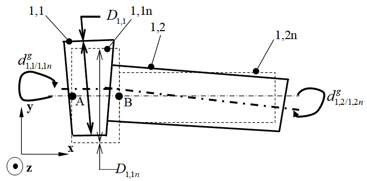
Figure 1 Geometric deviations (situation deviations and dimension deviations).

Situation deviations define the positioning of situation elements of the substituted surface in relation to those of the corresponding nominal surface being used as a reference.20 In Figure 1, d 1,1/1,1n g MathType@MTEF@5@5@+= feaagKart1ev2aaatCvAUfeBSjuyZL2yd9gzLbvyNv2CaerbuLwBLn hiov2DGi1BTfMBaeXatLxBI9gBaerbd9wDYLwzYbItLDharqqtubsr 4rNCHbGeaGqiVu0Je9sqqrpepC0xbbL8F4rqqrFfpeea0xe9Lq=Jc9 vqaqpepm0xbba9pwe9Q8fs0=yqaqpepae9pg0FirpepeKkFr0xfr=x fr=xb9adbaqaaeGaciGaaiaabaqaamaabaabaaGcbaqcLbsacaWGKb GcdaqhaaWcbaqcLbmacaaIXaGaaiilaiaaigdacaGGVaGaaGymaiaa cYcacaaIXaGaamOBaaWcbaqcLbmacaWGNbaaaaaa@40E9@ and d 1,2/1,2n g MathType@MTEF@5@5@+= feaagKart1ev2aaatCvAUfeBSjuyZL2yd9gzLbvyNv2CaerbuLwBLn hiov2DGi1BTfMBaeXatLxBI9gBaerbd9wDYLwzYbItLDharqqtubsr 4rNCHbGeaGqiVu0Je9sqqrpepC0xbbL8F4rqqrFfpeea0xe9Lq=Jc9 vqaqpepm0xbba9pwe9Q8fs0=yqaqpepae9pg0FirpepeKkFr0xfr=x fr=xb9adbaqaaeGaciGaaiaabaqaamaabaabaaGcbaqcLbsacaWGKb GcdaqhaaWcbaqcLbmacaaIXaGaaiilaiaaikdacaGGVaGaaGymaiaa cYcacaaIYaGaamOBaaWcbaqcLbmacaWGNbaaaaaa@40EB@ illustrate situation deviations between surfaces 1,1 and 1,1n and between surfaces 1,2 and 1,2n respectively. The difference between the diameter of the substituted surface, denoted D 1,1 MathType@MTEF@5@5@+= feaagKart1ev2aaatCvAUfeBSjuyZL2yd9gzLbvyNv2CaerbuLwBLn hiov2DGi1BTfMBaeXatLxBI9gBaerbd9wDYLwzYbItLDharqqtubsr 4rNCHbGeaGqiVu0Je9sqqrpepC0xbbL8F4rqqrFfpeea0xe9Lq=Jc9 vqaqpepm0xbba9pwe9Q8fs0=yqaqpepae9pg0FirpepeKkFr0xfr=x fr=xb9adbaqaaeGaciGaaiaabaqaamaabaabaaGcbaqcLbsacaWGeb GcdaWgaaWcbaqcLbmacaaIXaGaaiilaiaaigdaaSqabaaaaa@3AE2@ , and the diameter of the nominal surface, denoted D 1,1n MathType@MTEF@5@5@+= feaagKart1ev2aaatCvAUfeBSjuyZL2yd9gzLbvyNv2CaerbuLwBLn hiov2DGi1BTfMBaeXatLxBI9gBaerbd9wDYLwzYbItLDharqqtubsr 4rNCHbGeaGqiVu0Je9sqqrpepC0xbbL8F4rqqrFfpeea0xe9Lq=Jc9 vqaqpepm0xbba9pwe9Q8fs0=yqaqpepae9pg0FirpepeKkFr0xfr=x fr=xb9adbaqaaeGaciGaaiaabaqaamaabaabaaGcbaqcLbsacaWGeb GcdaWgaaWcbaqcLbmacaaIXaGaaiilaiaaigdacaWGUbaaleqaaaaa @3BD5@ , is the dimension deviation of a cylindrical surface denoted d 1,1 MathType@MTEF@5@5@+= feaagKart1ev2aaatCvAUfeBSjuyZL2yd9gzLbvyNv2CaerbuLwBLn hiov2DGi1BTfMBaeXatLxBI9gBaerbd9wDYLwzYbItLDharqqtubsr 4rNCHbGeaGqiVu0Je9sqqrpepC0xbbL8F4rqqrFfpeea0xe9Lq=Jc9 vqaqpepm0xbba9pwe9Q8fs0=yqaqpepae9pg0FirpepeKkFr0xfr=x fr=xb9adbaqaaeGaciGaaiaabaqaamaabaabaaGcbaqcLbsacaWGKb GcdaWgaaWcbaqcLbmacaaIXaGaaiilaiaaigdaaSqabaaaaa@3B02@ (see Figure 1):

D 1,1 D 1,1n = d 1,1 MathType@MTEF@5@5@+= feaagKart1ev2aaatCvAUfeBSjuyZL2yd9gzLbvyNv2CaerbuLwBLn hiov2DGi1BTfMBaeXatLxBI9gBaerbd9wDYLwzYbItLDharqqtubsr 4rNCHbGeaGqiVu0Je9sqqrpepC0xbbL8F4rqqrFfpeea0xe9Lq=Jc9 vqaqpepm0xbba9pwe9Q8fs0=yqaqpepae9pg0FirpepeKkFr0xfr=x fr=xb9adbaqaaeGaciGaaiaabaqaamaabaabaaGcbaqcLbsacaWGeb qcfa4aaSbaaSqaaKqzadGaaGymaiaacYcacaaIXaaaleqaaKqzGeGa eyOeI0IaamiraKqbaoaaBaaaleaajugWaiaaigdacaGGSaGaaGymai aad6gaaSqabaqcLbsacqGH9aqpcaWGKbqcfa4aaSbaaSqaaKqzadGa aGymaiaacYcacaaIXaaaleqaaaaa@494E@ (1)

The situation and dimension deviations define the geometric deviations of a part. Situation deviations can be formalised mathematically by a small displacement torsor27 to characterise the situation deviations between two surfaces.

The following equation expresses the small displacement torsor of substituted surface 1,1 in relation to the nominal surface 1,1n denoted [ d 1,1/1,1n g ] MathType@MTEF@5@5@+= feaagKart1ev2aaatCvAUfeBSjuyZL2yd9gzLbvyNv2CaerbuLwBLn hiov2DGi1BTfMBaeXatLxBI9gBaerbd9wDYLwzYbItLDharqqtubsr 4rNCHbGeaGqiVu0Je9sqqrpepC0xbbL8F4rqqrFfpeea0xe9Lq=Jc9 vqaqpepm0xbba9pwe9Q8fs0=yqaqpepae9pg0FirpepeKkFr0xfr=x fr=xb9adbaqaaeGaciGaaiaabaqaamaabaabaaGcbaqcfa4aamWaaO qaaKqzGeGaamizaKqbaoaaDaaaleaajugWaiaaigdacaGGSaGaaGym aiaac+cacaaIXaGaaiilaiaaigdacaWGUbaaleaajugWaiaadEgaaa aakiaawUfacaGLDbaaaaa@4401@ at point B:

[ d 1,1/1,1n g ]= [ ρ 1,1/1,1n ε B-1,1/1,1n ] B MathType@MTEF@5@5@+= feaagKart1ev2aaatCvAUfeBSjuyZL2yd9gzLbvyNv2CaerbuLwBLn hiov2DGi1BTfMBaeXatLxBI9gBaerbd9wDYLwzYbItLDharqqtubsr 4rNCHbGeaGqiVu0Je9sqqrpepC0xbbL8F4rqqrFfpeea0xe9Lq=Jc9 vqaqpepm0xbba9pwe9Q8fs0=yqaqpepae9pg0FirpepeKkFr0xfr=x fr=xb9adbaqaaeGaciGaaiaabeqaamaabaabaaGcbaqcfa4aamWaaO qaaKqzGeGaamizaKqbaoaaDaaaleaajugWaiaaigdacaGGSaGaaGym aiaac+cacaaIXaGaaiilaiaaigdacaWGUbaaleaajugWaiaadEgaaa aakiaawUfacaGLDbaajugibiabg2da9KqbaoaaBeaaleaajugibiaa bkeaaSqabaWaamWaaOqaaKqzadqbaeqabiqaaaGcbaqcLbmacaWHbp WcdaWgaaqaaKqzadGaaGymaiaacYcacaaIXaGaai4laiaaigdacaGG SaGaaGymaiaad6gaaSqabaaakeaajugWaiaahw7almaaBaaabaqcLb maciGGcbGaaiylaiaaigdacaGGSaGaaGymaiaac+cacaaIXaGaaiil aiaaigdacaWGUbaaleqaaaaaaOGaay5waiaaw2faaaaa@6017@ (2)

Vector ρ 1,1/1,1n MathType@MTEF@5@5@+= feaagKart1ev2aaatCvAUfeBSjuyZL2yd9gzLbvyNv2CaerbuLwBLn hiov2DGi1BTfMBaeXatLxBI9gBaerbd9wDYLwzYbItLDharqqtubsr 4rNCHbGeaGqiVu0Je9sqqrpepC0xbbL8F4rqqrFfpeea0xe9Lq=Jc9 vqaqpepm0xbba9pwe9Q8fs0=yqaqpepae9pg0FirpepeKkFr0xfr=x fr=xb9adbaqaaeGaciGaaiaabeqaamaabaabaaGcbaqcLbsacaWHbp qcfa4aaSbaaSqaaKqzadGaaGymaiaacYcacaaIXaGaai4laiaaigda caGGSaGaaGymaiaad6gaaSqabaaaaa@3FB7@ characterises the rotation deviations, while vector ε B-1,1/1,1n MathType@MTEF@5@5@+= feaagKart1ev2aaatCvAUfeBSjuyZL2yd9gzLbvyNv2CaerbuLwBLn hiov2DGi1BTfMBaeXatLxBI9gBaerbd9wDYLwzYbItLDharqqtubsr 4rNCHbGeaGqiVu0Je9sqqrpepC0xbbL8F4rqqrFfpeea0xe9Lq=Jc9 vqaqpepm0xbba9pwe9Q8fs0=yqaqpepae9pg0FirpepeKkFr0xfr=x fr=xb9adbaqaaeGaciGaaiaabeqaamaabaabaaGcbaqcLbsacaWH1o qcfa4aaSbaaSqaaGqaaKqzadGaa8Nqaiaab2cacaaIXaGaaiilaiaa igdacaGGVaGaaGymaiaacYcacaaIXaGaamOBaaWcbeaaaaa@4127@ characterises the translation deviations at point B (see Figure 1).

According to the property of the small displacements field, we than have:27

ε N-1,1/1,2 = ε M-1,1/1,2 +NM× ρ 1,1/1,2 N,Meuclideanspace MathType@MTEF@5@5@+= feaagKart1ev2aaatCvAUfeBSjuyZL2yd9gzLbvyNv2CaerbuLwBLn hiov2DGi1BTfMBaeXatLxBI9gBaerbd9wDYLwzYbItLDharqqtubsr 4rNCHbGeaGqiVu0Je9sqqrpepC0xbbL8F4rqqrFfpeea0xe9Lq=Jc9 vqaqpepm0xbba9pwe9Q8fs0=yqaqpepae9pg0FirpepeKkFr0xfr=x fr=xb9adbaqaaeGaciGaaiaabeqaamaabaabaaGcbaqcLbsacaWH1o qcfa4aaSbaaSqaaKqzadGaamOtaiaab2cacaaIXaGaaiilaiaaigda caGGVaGaaGymaiaacYcacaaIYaaaleqaaKqzGeGaeyypa0JaaCyTdK qbaoaaBaaaleaajugWaiaad2eacaqGTaGaaGymaiaacYcacaaIXaGa ai4laiaaigdacaGGSaGaaGOmaaWcbeaajugibiabgUcaRiaah6eaca WHnbGaey41aqRaaCyWdKqbaoaaBaaaleaajugWaiaaigdacaGGSaGa aGymaiaac+cacaaIXaGaaiilaiaaikdaaSqabaqcLbsacaaMf8Uaey iaIiIaamOtaiaacYcacqGHaiIicaWGnbGaeyicI4Saaeyzaiaabwha caqGJbGaaeiBaiaabMgacaqGKbGaaeyzaiaabggacaqGUbGaaGjbVl aabohacaqGWbGaaeyyaiaabogacaqGLbaaaa@6EFF@ (3)

Thus, the relative position between surfaces 1,1 and 1,2 can be deduced from the equation:

[ d 1,1/1,2 g ]=[ d 1,1/1,1n g ]+[ d 1,1n/1,2n g ]+[ d 1,2n/1,2 g ]=[ d 1,1/1,1n g ]+[ d 1,2n/1,2 g ] MathType@MTEF@5@5@+= feaagKart1ev2aaatCvAUfeBSjuyZL2yd9gzLbvyNv2CaerbuLwBLn hiov2DGi1BTfMBaeXatLxBI9gBaerbd9wDYLwzYbItLDharqqtubsr 4rNCHbGeaGqiVu0Je9sqqrpepC0xbbL8F4rqqrFfpeea0xe9Lq=Jc9 vqaqpepm0xbba9pwe9Q8fs0=yqaqpepae9pg0FirpepeKkFr0xfr=x fr=xb9adbaqaaeGaciGaaiaabaqaamaabaabaaGcbaqcfa4aamWaaO qaaKqzGeGaamizaKqbaoaaDaaaleaajugWaiaaigdacaGGSaGaaGym aiaac+cacaaIXaGaaiilaiaaikdaaSqaaKqzadGaam4zaaaaaOGaay 5waiaaw2faaKqzGeGaeyypa0tcfa4aamWaaOqaaKqzGeGaamizaKqb aoaaDaaaleaajugWaiaaigdacaGGSaGaaGymaiaac+cacaaIXaGaai ilaiaaigdacaWGUbaaleaajugWaiaadEgaaaaakiaawUfacaGLDbaa jugibiabgUcaRKqbaoaadmaakeaajugibiaadsgajuaGdaqhaaWcba qcLbmacaaIXaGaaiilaiaaigdacaWGUbGaai4laiaaigdacaGGSaGa aGOmaiaad6gaaSqaaKqzadGaam4zaaaaaOGaay5waiaaw2faaKqzGe Gaey4kaSscfa4aamWaaOqaaKqzGeGaamizaKqbaoaaDaaaleaajugW aiaaigdacaGGSaGaaGOmaiaad6gacaGGVaGaaGymaiaacYcacaaIYa aaleaajugWaiaadEgaaaaakiaawUfacaGLDbaajugibiabg2da9Kqb aoaadmaakeaajugibiaadsgajuaGdaqhaaWcbaqcLbmacaaIXaGaai ilaiaaigdacaGGVaGaaGymaiaacYcacaaIXaGaamOBaaWcbaqcLbma caWGNbaaaaGccaGLBbGaayzxaaqcLbsacqGHRaWkjuaGdaWadaGcba qcLbsacaWGKbqcfa4aa0baaSqaaKqzadGaaGymaiaacYcacaaIYaGa amOBaiaac+cacaaIXaGaaiilaiaaikdaaSqaaKqzadGaam4zaaaaaO Gaay5waiaaw2faaaaa@91C0@ (4)

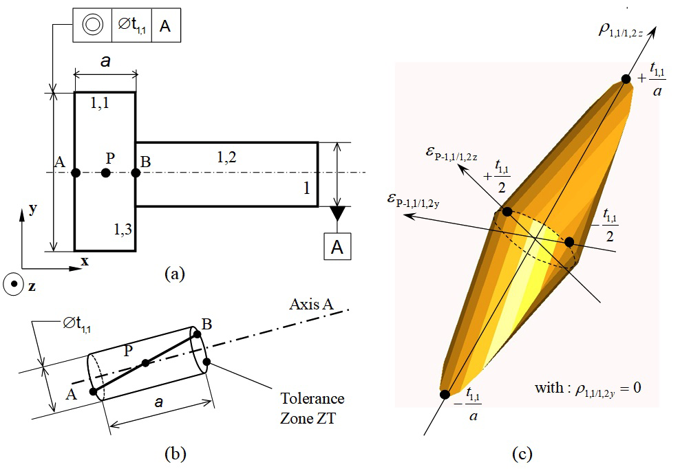
The geometric deviations between the two nominal surfaces 1,1n and 1,2n are by definition null. Let us consider the coaxiality specification shown in Figure 2a. According to,4 the axis of the cylindrical substituted surface 1,1 is contained within a tolerance zone ZT. ZT is a cylinder of diameter t 1,1 MathType@MTEF@5@5@+= feaagKart1ev2aaatCvAUfeBSjuyZL2yd9gzLbvyNv2CaerbuLwBLn hiov2DGi1BTfMBaeXatLxBI9gBaerbd9wDYLwzYbItLDharqqtubsr 4rNCHbGeaGqiVu0Je9sqqrpepC0xbbL8F4rqqrFfpeea0xe9Lq=Jc9 vqaqpepm0xbba9pwe9Q8fs0=yqaqpepae9pg0FirpepeKkFr0xfr=x fr=xb9adbaqaaeGaciGaaiaabaqaamaabaabaaGcbaqcLbsacqGHfi IXcaWG0bqcfa4aaSbaaSqaaKqzadGaaGymaiaacYcacaaIXaaaleqa aaaa@3D0F@ and its axis coincides with axis A (axis of cylinder 1,2), see Figure 2b. To ensure that the axis of surface 1,1 is located within the tolerance zone ZT, the following equation should be written at the two extremities A and B, where n θi MathType@MTEF@5@5@+= feaagKart1ev2aaatCvAUfeBSjuyZL2yd9gzLbvyNv2CaerbuLwBLn hiov2DGi1BTfMBaeXatLxBI9gBaerbd9wDYLwzYbItLDharqqtubsr 4rNCHbGeaGqiVu0Je9sqqrpepC0xbbL8F4rqqrFfpeea0xe9Lq=Jc9 vqaqpepm0xbba9pwe9Q8fs0=yqaqpepae9pg0FirpepeKkFr0xfr=x fr=xb9adbaqaaeGaciGaaiaabeqaamaabaabaaGcbaqcLbsacaWHUb qcfa4aaSbaaSqaaKqzadGaeqiUdeNaamyAaaWcbeaaaaa@3C13@ is a unitary vector orthogonal to axis A and n MathType@MTEF@5@5@+= feaagKart1ev2aaatCvAUfeBSjuyZL2yd9gzLbvyNv2CaerbuLwBLn hiov2DGi1BTfMBaeXatLxBI9gBaerbd9wDYLwzYbItLDharqqtubsr 4rNCHbGeaGqiVu0Je9sqqrpepC0xbbL8F4rqqrFfpeea0xe9Lq=Jc9 vqaqpepm0xbba9pwe9Q8fs0=yqaqpepae9pg0FirpepeKkFr0xfr=x fr=xb9adbaqaaeGaciGaaiaabeqaamaabaabaaGcbaqcLbsacaWGUb aaaa@3778@ is the angular discretization step around axis A:

{ t 1,1 2 ε A-1,1/1,2 . n θi t 1,1 2 t 1,1 2 ε B-1,1/1,2 . n θi t 1,1 2 }with{ n θi =cos θ i .y+sin θ i .z θ i =i π n ,0i<nand( i,n ) MathType@MTEF@5@5@+= feaagKart1ev2aaatCvAUfeBSjuyZL2yd9gzLbvyNv2CaerbuLwBLn hiov2DGi1BTfMBaeXatLxBI9gBaerbd9wDYLwzYbItLDharqqtubsr 4rNCHbGeaGqiVu0Je9sqqrpepC0xbbL8F4rqqrFfpeea0xe9Lq=Jc9 vqaqpepm0xbba9pwe9Q8fs0=yqaqpepae9pg0FirpepeKkFr0xfr=x fr=xb9adbaqaaeGaciGaaiaabeqaamaabaabaaGcbaqcfa4aaiWaaK qzGeabaeqakeaajugibiabgkHiTKqbaoaalaaakeaajugibiaadsha juaGdaWgaaWcbaqcLbsacaaIXaGaaiilaiaaigdaaSqabaaakeaaju gibiaaikdaaaGaeyizImQaaCyTdKqbaoaaBaaaleaajugWaiaadgea caqGTaGaaGymaiaacYcacaaIXaGaai4laiaaigdacaGGSaGaaGOmaa Wcbeaajugibiaac6cacaWHUbqcfa4aaSbaaSqaaKqzadGaeqiUdeNa amyAaaWcbeaajugibiabgsMiJMqbaoaalaaakeaajugibiaadshaju aGdaWgaaWcbaqcLbsacaaIXaGaaiilaiaaigdaaSqabaaakeaajugi biaaikdaaaaakeaajugibiabgkHiTKqbaoaalaaakeaajugibiaads hajuaGdaWgaaWcbaqcLbsacaaIXaGaaiilaiaaigdaaSqabaaakeaa jugibiaaikdaaaGaeyizImQaaCyTdKqbaoaaBaaaleaajugWaiaadk eacaqGTaGaaGymaiaacYcacaaIXaGaai4laiaaigdacaGGSaGaaGOm aaWcbeaajugibiaac6cacaWHUbqcfa4aaSbaaSqaaKqzadGaeqiUde NaamyAaaWcbeaajugibiabgsMiJMqbaoaalaaakeaajugibiaadsha juaGdaWgaaWcbaqcLbsacaaIXaGaaiilaiaaigdaaSqabaaakeaaju gibiaaikdaaaaaaOGaay5Eaiaaw2haaKqzGeGaaGjbVlaabEhacaqG PbGaaeiDaiaabIgajuaGdaGabaGcbaqcLbsacaaMe8Ebaeaabiqaaa GcbaqcLbsacaWHUbqcfa4aaSbaaSqaaKqzadGaeqiUdeNaamyAaaWc beaajugibiabg2da9iGacogacaGGVbGaai4CaiabeI7aXLqbaoaaBa aaleaajugWaiaadMgaaSqabaqcLbsacaGGUaGaaCyEaiabgUcaRiGa cohacaGGPbGaaiOBaiabeI7aXLqbaoaaBaaaleaajugWaiaadMgaaS qabaqcLbsacaGGUaGaaCOEaaGcbaqcLbsacqaH4oqClmaaBaaabaqc LbmacaWGPbaaleqaaKqzGeGaeyypa0JaamyAaKqbaoaalaaakeaaju gibiabec8aWbGcbaqcLbsacaWGUbaaaiaaysW7caqGSaGaaGjbVlaa icdacqGHKjYOcaWGPbGaeyipaWJaamOBaiaaysW7caaMe8Uaaeyyai aab6gacaqGKbGaaGjbVNqbaoaabmaakeaajugibiaadMgacaGGSaGa amOBaaGccaGLOaGaayzkaaqcLbsacqGHiiIZcqWIvesPaaaakiaawU haaKqzGeGaaGjbVdaa@CE13@ (5)

Figure 2 Coaxiality modelled by a geometric polytope.

By expressing equation (5) in terms of  (3) as a function of translation deviations at point P in the middle of the line segment limited by A and B, in the base (x,y,z)if we postulate AB=a we have:

{ t 1,1 2 cos θ i .( ε P-1,1/1,2y a 2 . ρ 1,1/1,2z )+sin θ i .( ε P-1,1/1,2z + a 2 . ρ 1,1/1,2y ) t 1,1 2 t 1,1 2 cos θ i .( ε P-1,1/1,2y + a 2 . ρ 1,1/1,2z )+sin θ i .( ε P-1,1/1,2z a 2 . ρ 1,1/1,2y ) t 1,1 2 } with :  θ i =i π n ,0i<nand( i,n ) MathType@MTEF@5@5@+= feaagKart1ev2aaatCvAUfeBSjuyZL2yd9gzLbvyNv2CaerbuLwBLn hiov2DGi1BTfMBaeXatLxBI9gBaerbd9wDYLwzYbItLDharqqtubsr 4rNCHbGeaGqiVu0Je9sqqrpepC0xbbL8F4rqqrFfpeea0xe9Lq=Jc9 vqaqpepm0xbba9pwe9Q8fs0=yqaqpepae9pg0FirpepeKkFr0xfr=x fr=xb9adbaqaaeGaciGaaiaabaqaamaabaabaaGceaqabeaajuaGda GadaqcLbsaeaqabOqaaKqzGeGaeyOeI0scfa4aaSaaaOqaaKqzGeGa amiDaKqbaoaaBaaaleaajugibiaaigdacaGGSaGaaGymaaWcbeaaaO qaaKqzGeGaaGOmaaaacqGHKjYOciGGJbGaai4BaiaacohacqaH4oqC juaGdaWgaaWcbaqcLbmacaWGPbaaleqaaKqzGeGaaiOlaKqbaoaabm aakeaajugibiabew7aLLqbaoaaBaaaleaajugWaiaabcfacaqGTaGa aGymaiaacYcacaaIXaGaai4laiaaigdacaGGSaGaaGOmaiaadMhaaS qabaqcLbsacqGHsisljuaGdaWcaaGcbaqcLbsacaWGHbaakeaajugi biaaikdaaaGaaiOlaiabeg8aYLqbaoaaBaaaleaajugWaiaaigdaca GGSaGaaGymaiaac+cacaaIXaGaaiilaiaaikdacaWG6baaleqaaaGc caGLOaGaayzkaaqcLbsacqGHRaWkciGGZbGaaiyAaiaac6gacqaH4o qCjuaGdaWgaaWcbaqcLbmacaWGPbaaleqaaKqzGeGaaiOlaKqbaoaa bmaakeaajugibiabew7aLLqbaoaaBaaaleaajugWaiaabcfacaqGTa GaaGymaiaacYcacaaIXaGaai4laiaaigdacaGGSaGaaGOmaiaadQha aSqabaqcLbsacqGHRaWkjuaGdaWcaaGcbaqcLbsacaWGHbaakeaaju gibiaaikdaaaGaaiOlaiabeg8aYLqbaoaaBaaaleaajugWaiaaigda caGGSaGaaGymaiaac+cacaaIXaGaaiilaiaaikdacaWG5baaleqaaa GccaGLOaGaayzkaaqcLbsacqGHKjYOjuaGdaWcaaGcbaqcLbsacaWG 0bqcfa4aaSbaaSqaaKqzGeGaaGymaiaacYcacaaIXaaaleqaaaGcba qcLbsacaaIYaaaaaGcbaqcLbsacqGHsisljuaGdaWcaaGcbaqcLbsa caWG0bqcfa4aaSbaaSqaaKqzGeGaaGymaiaacYcacaaIXaaaleqaaa GcbaqcLbsacaaIYaaaaiabgsMiJkGacogacaGGVbGaai4CaiabeI7a XLqbaoaaBaaaleaajugWaiaadMgaaSqabaqcLbsacaGGUaqcfa4aae WaaOqaaKqzGeGaeqyTduwcfa4aaSbaaSqaaKqzadGaaeiuaiaab2ca caaIXaGaaiilaiaaigdacaGGVaGaaGymaiaacYcacaaIYaGaamyEaa WcbeaajugibiabgUcaRKqbaoaalaaakeaajugibiaadggaaOqaaKqz GeGaaGOmaaaacaGGUaGaeqyWdixcfa4aaSbaaSqaaKqzadGaaGymai aacYcacaaIXaGaai4laiaaigdacaGGSaGaaGOmaiaadQhaaSqabaaa kiaawIcacaGLPaaajugibiabgUcaRiGacohacaGGPbGaaiOBaiabeI 7aXLqbaoaaBaaaleaajugWaiaadMgaaSqabaqcLbsacaGGUaqcfa4a aeWaaOqaaKqzGeGaeqyTduwcfa4aaSbaaSqaaKqzadGaaeiuaiaab2 cacaaIXaGaaiilaiaaigdacaGGVaGaaGymaiaacYcacaaIYaGaamOE aaWcbeaajugibiabgkHiTKqbaoaalaaakeaajugibiaadggaaOqaaK qzGeGaaGOmaaaacaGGUaGaeqyWdixcfa4aaSbaaSqaaKqzadGaaGym aiaacYcacaaIXaGaai4laiaaigdacaGGSaGaaGOmaiaadMhaaSqaba aakiaawIcacaGLPaaajugibiabgsMiJMqbaoaalaaakeaajugibiaa dshajuaGdaWgaaWcbaqcLbsacaaIXaGaaiilaiaaigdaaSqabaaake aajugibiaaikdaaaaaaOGaay5Eaiaaw2haaaqaaKqzGeGaae4Daiaa bMgacaqG0bGaaeiAaiaabccacaqG6aGaaeiiaiabeI7aXLqbaoaaBa aaleaajugWaiaadMgaaSqabaqcLbsacqGH9aqpcaWGPbqcfa4aaSaa aOqaaKqzGeGaeqiWdahakeaajugibiaad6gaaaGaaGjbVlaabYcaca aMe8UaaGimaiabgsMiJkaadMgacqGH8aapcaWGUbGaaGjbVlaaysW7 caqGHbGaaeOBaiaabsgacaaMe8Ecfa4aaeWaaOqaaKqzGeGaamyAai aacYcacaWGUbaakiaawIcacaGLPaaajugibiabgIGiolablwriLcaa aa@25B1@ (6)

The equations in (6) form a finite set of closed halfspaces of 4 MathType@MTEF@5@5@+= feaagKart1ev2aqatCvAUfeBSjuyZL2yd9gzLbvyNv2CaerbuLwBLn hiov2DGi1BTfMBaeXatLxBI9gBaerbd9wDYLwzYbItLDharqqtubsr 4rNCHbGeaGqiVu0Je9sqqrpepC0xbbL8F4rqqrFfpeea0xe9Lq=Jc9 vqaqpepm0xbba9pwe9Q8fs0=yqaqpepae9pg0FirpepeKkFr0xfr=x fr=xb9adbaqaaeGaciGaaiaabeqaamaabaabaaGcbaqcLbsacqWIDe sOjuaGdaahaaWcbeqaaKqzadGaaGinaaaaaaa@3A9D@ . Respecting these equations (6) can be formalised by an intersection limited to a finite number of closed halfspaces of which the boundaries are hyperplanes of 4 MathType@MTEF@5@5@+= feaagKart1ev2aqatCvAUfeBSjuyZL2yd9gzLbvyNv2CaerbuLwBLn hiov2DGi1BTfMBaeXatLxBI9gBaerbd9wDYLwzYbItLDharqqtubsr 4rNCHbGeaGqiVu0Je9sqqrpepC0xbbL8F4rqqrFfpeea0xe9Lq=Jc9 vqaqpepm0xbba9pwe9Q8fs0=yqaqpepae9pg0FirpepeKkFr0xfr=x fr=xb9adbaqaaeGaciGaaiaabeqaamaabaabaaGcbaqcLbsacqWIDe sOjuaGdaahaaWcbeqaaKqzadGaaGinaaaaaaa@3A9D@ .13 Generally, the H-representation of a polytope of n MathType@MTEF@5@5@+= feaagKart1ev2aqatCvAUfeBSjuyZL2yd9gzLbvyNv2CaerbuLwBLn hiov2DGi1BTfMBaeXatLxBI9gBaerbd9wDYLwzYbItLDharqqtubsr 4rNCHbGeaGqiVu0Je9sqqrpepC0xbbL8F4rqqrFfpeea0xe9Lq=Jc9 vqaqpepm0xbba9pwe9Q8fs0=yqaqpepae9pg0FirpepeKkFr0xfr=x fr=xb9adbaqaaeGaciGaaiaabeqaamaabaabaaGcbaqcLbsacqWIDe sOjuaGdaahaaWcbeqaaKqzadGaamOBaaaaaaa@3AD2@ can then be formalised.28,29 Thus the equations in (6) characterise a polytope which we will call a geometric polytope, denoted D 1,1/1,2 g MathType@MTEF@5@5@+= feaagKart1ev2aaatCvAUfeBSjuyZL2yd9gzLbvyNv2CaerbuLwBLn hiov2DGi1BTfMBaeXatLxBI9gBaerbd9wDYLwzYbItLDharqqtubsr 4rNCHbGeaGqiVu0Je9sqqrpepC0xbbL8F4rqqrFfpeea0xe9Lq=Jc9 vqaqpepm0xbba9pwe9Q8fs0=yqaqpepae9pg0FirpepeKkFr0xfr=x fr=xb9adbaqaaeGaciGaaiaabaqaamaabaabaaGcbaWefv3ySLgzgj xyRrxDYbqeguuDJXwAKbIrYf2A0vNCaGqbaKqzGeGae83aWtucfa4a a0baaSqaaKqzadGaaGymaiaacYcacaaIXaGaai4laiaaigdacaGGSa GaaGOmaaWcbaqcLbmacaqGNbaaaaaa@4C0D@ , of the coaxiality specification of 1,1 in relation to 1,2. This is a 4-polytope which can be represented graphically in 3 MathType@MTEF@5@5@+= feaagKart1ev2aqatCvAUfeBSjuyZL2yd9gzLbvyNv2CaerbuLwBLn hiov2DGi1BTfMBaeXatLxBI9gBaerbd9wDYLwzYbItLDharqqtubsr 4rNCHbGeaGqiVu0Je9sqqrpepC0xbbL8F4rqqrFfpeea0xe9Lq=Jc9 vqaqpepm0xbba9pwe9Q8fs0=yqaqpepae9pg0FirpepeKkFr0xfr=x fr=xb9adbaqaaeGaciGaaiaabeqaamaabaabaaGcbaqcLbsacqWIDe sOjuaGdaahaaWcbeqaaKqzadGaaG4maaaaaaa@3A9C@ for ρ 1,1/1,2y =0 MathType@MTEF@5@5@+= feaagKart1ev2aqatCvAUfeBSjuyZL2yd9gzLbvyNv2CaerbuLwBLn hiov2DGi1BTfMBaeXatLxBI9gBaerbd9wDYLwzYbItLDharqqtubsr 4rNCHbGeaGqiVu0Je9sqqrpepC0xbbL8F4rqqrFfpeea0xe9Lq=Jc9 vqaqpepm0xbba9pwe9Q8fs0=yqaqpepae9pg0FirpepeKkFr0xfr=x fr=xb9adbaqaaeGaciGaaiaabaqaamaabaabaaGcbaqcLbsacqaHbp GCjuaGdaWgaaWcbaqcLbmacaaIXaGaaiilaiaaigdacaGGVaGaaGym aiaacYcacaaIYaGaamyEaaWcbeaajugibiabg2da9iaaicdaaaa@4285@ for example, see Figure 2c. In the same way, it is possible to define a geometric polytope that represents the boundaries of the situation deviations of all orientation or position specifications.13

Characterisation of the geometric deviations between two surfaces potentially in contact:

The definition of contact between two surfaces, i.e. a joint, can be expressed using a set of parameters. There have been several studies on this subject.30-32 Hereafter we will use the definition proposed in,33 which is a direct application of that proposed in.32 A joint is defined by its type (planar pair, cylindrical pair, ball and cylinder pair, etc.),34 its situation element(s) (plane, line, point), its nature (fixed, sliding or floating) and by its clearance (minimal clearance, maximal clearance).33

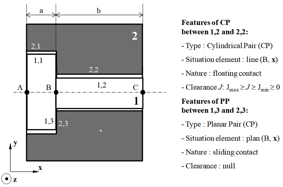
Consider Figure 3: two parts 1 and 2 are in contact via their respective surfaces 1,2 and 2,2 and also via surfaces 1,3 and 2,3.The joint between surfaces 1,2 and 2,2 is a cylindrical pair type and the situation element is a line (B,x). Contact is of a floating nature, with clearance J being the difference between the diameter of surface 2,2 (bore) and the diameter of surface 1,2 (shaft):

J= D 2,2 D 1,2 MathType@MTEF@5@5@+= feaagKart1ev2aaatCvAUfeBSjuyZL2yd9gzLbvyNv2CaerbuLwBLn hiov2DGi1BTfMBaeXatLxBI9gBaerbd9wDYLwzYbItLDharqqtubsr 4rNCHbGeaGqiVu0Je9sqqrpepC0xbbL8F4rqqrFfpeea0xe9Lq=Jc9 vqaqpepm0xbba9pwe9Q8fs0=yqaqpepae9pg0FirpepeKkFr0xfr=x fr=xb9adbaqaaeGaciGaaiaabeqaamaabaabaaGcbaqcLbsacaWGkb Gaeyypa0JaamiraKqbaoaaBaaaleaajugWaiaaikdacaGGSaGaaGOm aaWcbeaajugibiabgkHiTiaadseajuaGdaWgaaWcbaqcLbmacaaIXa GaaiilaiaaikdaaSqabaaaaa@439D@ (7)

Figure 3 Contact specifications.

The joint between surfaces 1,3 and 2,3 is a planar pair type and the situation element is a plane (B,x). Contact is of a sliding nature and hence clearance is null.33 Situation deviations between two surfaces that are potentially in contact can be formalised mathematically by a small displacement torsor. The torsor d 1,2/2,2 MathType@MTEF@5@5@+= feaagKart1ev2aaatCvAUfeBSjuyZL2yd9gzLbvyNv2CaerbuLwBLn hiov2DGi1BTfMBaeXatLxBI9gBaerbd9wDYLwzYbItLDharqqtubsr 4rNCHbGeaGqiVu0Je9sqqrpepC0xbbL8F4rqqrFfpeea0xe9Lq=Jc9 vqaqpepm0xbba9pwe9Q8fs0=yqaqpepae9pg0FirpepeKkFr0xfr=x fr=xb9adbaqaaeGaciGaaiaabaqaamaabaabaaGcbaqcLbsaqqaaaa aaaaGtVLMCa8qacaWGKbqcfa4aaSbaaSqaaKqzadGaaGymaiaacYca caaIYaGaai4laiaaikdacaGGSaGaaGOmaaWcbeaaaaa@401E@ defines deviations in the joint between surfaces 1,2 and 2,2 at point B:

[ d 1,2/2,2 ]= [ ρ 1,2/2,2 ε B-1,2/2,2 ] B MathType@MTEF@5@5@+= feaagKart1ev2aaatCvAUfeBSjuyZL2yd9gzLbvyNv2CaerbuLwBLn hiov2DGi1BTfMBaeXatLxBI9gBaerbd9wDYLwzYbItLDharqqtubsr 4rNCHbGeaGqiVu0Je9sqqrpepC0xbbL8F4rqqrFfpeea0xe9Lq=Jc9 vqaqpepm0xbba9pwe9Q8fs0=yqaqpepae9pg0FirpepeKkFr0xfr=x fr=xb9adbaqaaeGaciGaaiaabeqaamaabaabaaGcbaqcfa4aamWaaO qaaKqzGeGaamizaKqbaoaaDaaaleaajugWaiaaigdacaGGSaGaaGOm aiaac+cacaaIYaGaaiilaiaaikdaaSqaaaaaaOGaay5waiaaw2faaK qzGeGaeyypa0tcfa4aaSraaSqaaKqzGeGaaeOqaaWcbeaadaWadaGc baqcLbmafaqabeGabaaakeaajugWaiaahg8almaaBaaabaqcLbmaca aIXaGaaiilaiaaikdacaGGVaGaaGOmaiaacYcacaaIYaaaleqaaaGc baqcLbmacaWH1oWcdaWgaaqaaGqaaKqzadGaa8Nqaiaab2cacaaIXa GaaiilaiaaikdacaGGVaGaaGOmaiaacYcacaaIYaaaleqaaaaaaOGa ay5waiaaw2faaaaa@5B30@ (8)

Equation (9) defines the different positions between surfaces potentially in contact for any point N on the contact surface E c MathType@MTEF@5@5@+= feaagKart1ev2aaatCvAUfeBSjuyZL2yd9gzLbvyNv2CaerbuLwBLn hiov2DGi1BTfMBaeXatLxBI9gBaerbd9wDYLwzYbItLDharqqtubsr 4rNCHbGeaGqiVu0Je9sqqrpepC0xbbL8F4rqqrFfpeea0xe9Lq=Jc9 vqaqpepm0xbba9pwe9Q8fs0=yqaqpepae9pg0FirpepeKkFr0xfr=x fr=xb9adbaqaaeGaciGaaiaabeqaamaabaabaaGcbaqcLbsacaWGfb qcfa4aaSbaaSqaaKqzadGaam4yaaWcbeaaaaa@3A2A@ according to n N MathType@MTEF@5@5@+= feaagKart1ev2aaatCvAUfeBSjuyZL2yd9gzLbvyNv2CaerbuLwBLn hiov2DGi1BTfMBaeXatLxBI9gBaerbd9wDYLwzYbItLDharqqtubsr 4rNCHbGeaGqiVu0Je9sqqrpepC0xbbL8F4rqqrFfpeea0xe9Lq=Jc9 vqaqpepm0xbba9pwe9Q8fs0=yqaqpepae9pg0FirpepeKkFr0xfr=x fr=xb9adbaqaaeGaciGaaiaabeqaamaabaabaaGcbaqcLbsacaWHUb qcfa4aaSbaaSqaaGqaaKqzadGaa8NtaaWcbeaaaaa@3A47@ , with a vector normal to E c MathType@MTEF@5@5@+= feaagKart1ev2aaatCvAUfeBSjuyZL2yd9gzLbvyNv2CaerbuLwBLn hiov2DGi1BTfMBaeXatLxBI9gBaerbd9wDYLwzYbItLDharqqtubsr 4rNCHbGeaGqiVu0Je9sqqrpepC0xbbL8F4rqqrFfpeea0xe9Lq=Jc9 vqaqpepm0xbba9pwe9Q8fs0=yqaqpepae9pg0FirpepeKkFr0xfr=x fr=xb9adbaqaaeGaciGaaiaabeqaamaabaabaaGcbaqcLbsacaWGfb qcfa4aaSbaaSqaaKqzadGaam4yaaWcbeaaaaa@3A2A@ at point N:

N E c ε N-1,2/2,2 . n N J MathType@MTEF@5@5@+= feaagKart1ev2aaatCvAUfeBSjuyZL2yd9gzLbvyNv2CaerbuLwBLn hiov2DGi1BTfMBaeXatLxBI9gBaerbd9wDYLwzYbItLDharqqtubsr 4rNCHbGeaGqiVu0Je9sqqrpepC0xbbL8F4rqqrFfpeea0xe9Lq=Jc9 vqaqpepm0xbba9pwe9Q8fs0=yqaqpepae9pg0FirpepeKkFr0xfr=x fr=xb9adbaqaaeGaciGaaiaabeqaamaabaabaaGcbaqcLbsacqGHai IicaWGobGaeyicI4SaamyraKqbaoaaBaaaleaajugWaiaadogaaSqa baqcLbsacaaMf8UaaGzbVlaahw7ajuaGdaWgaaWcbaacbaqcLbmaca WFobGaaeylaiaaigdacaGGSaGaaGOmaiaac+cacaaIYaGaaiilaiaa ikdaaSqabaqcLbsacaGGUaGaaCOBaKqbaoaaBaaaleaajugWaiaa=5 eaaSqabaqcLbsacqGHKjYOcaWGkbaaaa@52C7@ (9)

The contact surface E c MathType@MTEF@5@5@+= feaagKart1ev2aaatCvAUfeBSjuyZL2yd9gzLbvyNv2CaerbuLwBLn hiov2DGi1BTfMBaeXatLxBI9gBaerbd9wDYLwzYbItLDharqqtubsr 4rNCHbGeaGqiVu0Je9sqqrpepC0xbbL8F4rqqrFfpeea0xe9Lq=Jc9 vqaqpepm0xbba9pwe9Q8fs0=yqaqpepae9pg0FirpepeKkFr0xfr=x fr=xb9adbaqaaeGaciGaaiaabeqaamaabaabaaGcbaqcLbsacaWGfb qcfa4aaSbaaSqaaKqzadGaam4yaaWcbeaaaaa@3A2A@ is the intersection of the surfaces in contact in the specific configuration where:

  1. Situation deviations between the two surfaces are null (the situation elements of the surfaces are the same),
  2. Intrinsic dimensions (diameter of a cylinder, angle at the top of a cone, etc.) of the two surfaces are the same.

Distance dN is the local distance in N between the two surfaces in contact according to nN specifically in the position where situation deviations between the two surfaces are null. In the example of contact between surfaces 1,2 and 2,2, E c MathType@MTEF@5@5@+= feaagKart1ev2aaatCvAUfeBSjuyZL2yd9gzLbvyNv2CaerbuLwBLn hiov2DGi1BTfMBaeXatLxBI9gBaerbd9wDYLwzYbItLDharqqtubsr 4rNCHbGeaGqiVu0Je9sqqrpepC0xbbL8F4rqqrFfpeea0xe9Lq=Jc9 vqaqpepm0xbba9pwe9Q8fs0=yqaqpepae9pg0FirpepeKkFr0xfr=x fr=xb9adbaqaaeGaciGaaiaabeqaamaabaabaaGcbaqcLbsacaWGfb qcfa4aaSbaaSqaaKqzadGaam4yaaWcbeaaaaa@3A2A@ is a cylinder and its axis is the line segment [B,C] and d N = J 2 MathType@MTEF@5@5@+= feaagKart1ev2aaatCvAUfeBSjuyZL2yd9gzLbvyNv2CaerbuLwBLn hiov2DGi1BTfMBaeXatLxBI9gBaerbd9wDYLwzYbItLDharqqtubsr 4rNCHbGeaGqiVu0Je9sqqrpepC0xbbL8F4rqqrFfpeea0xe9Lq=Jc9 vqaqpepm0xbba9pwe9Q8fs0=yqaqpepae9pg0FirpepeKkFr0xfr=x fr=xb9adbaqaaeGaciGaaiaabeqaamaabaabaaGcbaqcLbsacaWGKb qcfa4aaSbaaSqaaKqzadGaamOtaaWcbeaajugibiabg2da9Kqbaoaa laaakeaajugibiaadQeaaOqaaKqzGeGaaGOmaaaaaaa@3F24@ .

As when characterising the geometric deviations of a part, equation (9) should be written at the two extremities B and C of the axis of the cylindrical contact surface where n is the angular discretization step around axis (B,x) of the contact surface cylinder:

{ ε B-1,2/2,2 . n θi J 2 ε C-1,2/2,2 . n θi J 2 }with{ n θi =cos θ i .y+sin θ i .z θ i =i 2π n ,0i<net( i,n ) { J 2 ε B-1,2/2,2 . n θi J 2 J 2 ε C-1,2/2,2 . n θi J 2 }with{ n θi =cos θ i .y+sin θ i .z θ i =i π n ,0i<net( i,n ) MathType@MTEF@5@5@+= feaagKart1ev2aaatCvAUfeBSjuyZL2yd9gzLbvyNv2CaerbuLwBLn hiov2DGi1BTfMBaeXatLxBI9gBaerbd9wDYLwzYbItLDharqqtubsr 4rNCHbGeaGqiVu0Je9sqqrpepC0xbbL8F4rqqrFfpeea0xe9Lq=Jc9 vqaqpepm0xbba9pwe9Q8fs0=yqaqpepae9pg0FirpepeKkFr0xfr=x fr=xb9adbaqaaeGaciGaaiaabeqaamaabaabaaGceaqabeaajuaGda GadaqcLbsaeaqabOqaaKqzGeGaaCyTdKqbaoaaBaaaleaajugWaiaa bkeacaqGTaGaaGymaiaacYcacaaIYaGaai4laiaaikdacaGGSaGaaG OmaaWcbeaajugibiaac6cacaWHUbqcfa4aaSbaaSqaaKqzadGaeqiU deNaamyAaaWcbeaajugibiabgsMiJMqbaoaalaaakeaajugibiaadQ eaaOqaaKqzGeGaaGOmaaaaaOqaaKqzGeGaaCyTdKqbaoaaBaaaleaa jugWaiaaboeacaqGTaGaaGymaiaacYcacaaIYaGaai4laiaaikdaca GGSaGaaGOmaaWcbeaajugibiaac6cacaWHUbqcfa4aaSbaaSqaaKqz adGaeqiUdeNaamyAaaWcbeaajugibiabgsMiJMqbaoaalaaakeaaju gibiaadQeaaOqaaKqzGeGaaGOmaaaaaaGccaGL7bGaayzFaaqcLbsa caaMe8Uaae4DaiaabMgacaqG0bGaaeiAaKqbaoaaceaakeaajugibi aaysW7faqaaeGabaaakeaajugibiaah6gajuaGdaWgaaWcbaqcLbma cqaH4oqCcaWGPbaaleqaaKqzGeGaeyypa0Jaci4yaiaac+gacaGGZb GaeqiUdexcfa4aaSbaaSqaaKqzadGaamyAaaWcbeaajugibiaac6ca caWH5bGaey4kaSIaci4CaiaacMgacaGGUbGaeqiUdexcfa4aaSbaaS qaaKqzadGaamyAaaWcbeaajugibiaac6cacaWH6baakeaajugibiab eI7aXLqbaoaaBaaaleaajugWaiaadMgaaSqabaqcLbsacqGH9aqpca WGPbqcfa4aaSaaaOqaaKqzGeGaaGOmaiabec8aWbGcbaqcLbsacaWG UbaaaiaaysW7caqGSaGaaGjbVlaaicdacqGHKjYOcaWGPbGaeyipaW JaamOBaiaaysW7caaMe8UaaeyzaiaabshacaaMe8Ecfa4aaeWaaOqa aKqzGeGaamyAaiaacYcacaWGUbaakiaawIcacaGLPaaajugibiabgI GiolablwriLcaaaOGaay5EaaqcLbsacaaMe8UaeyO0H4nakeaajuaG daGadaqcLbsaeaqabOqaaKqzGeGaeyOeI0scfa4aaSaaaOqaaKqzGe GaamOsaaGcbaqcLbsacaaIYaaaaiabgsMiJkaahw7ajuaGdaWgaaWc baqcLbmacaqGcbGaaeylaiaaigdacaGGSaGaaGOmaiaac+cacaaIYa GaaiilaiaaikdaaSqabaqcLbsacaGGUaGaaCOBaKqbaoaaBaaaleaa jugWaiabeI7aXjaadMgaaSqabaqcLbsacqGHKjYOjuaGdaWcaaGcba qcLbsacaWGkbaakeaajugibiaaikdaaaaakeaajugibiabgkHiTKqb aoaalaaakeaajugibiaadQeaaOqaaKqzGeGaaGOmaaaacqGHKjYOca WH1oqcfa4aaSbaaSqaaKqzadGaae4qaiaab2cacaaIXaGaaiilaiaa ikdacaGGVaGaaGOmaiaacYcacaaIYaaaleqaaKqzGeGaaiOlaiaah6 gajuaGdaWgaaWcbaqcLbmacqaH4oqCcaWGPbaaleqaaKqzGeGaeyiz ImAcfa4aaSaaaOqaaKqzGeGaamOsaaGcbaqcLbsacaaIYaaaaaaaki aawUhacaGL9baajugibiaaysW7caqG3bGaaeyAaiaabshacaqGObqc fa4aaiqaaOqaaKqzGeGaaGjbVxaabaqaceaaaOqaaKqzGeGaaCOBaK qbaoaaBaaaleaajugWaiabeI7aXjaadMgaaSqabaqcLbsacqGH9aqp ciGGJbGaai4BaiaacohacqaH4oqCjuaGdaWgaaWcbaqcLbmacaWGPb aaleqaaKqzGeGaaiOlaiaahMhacqGHRaWkciGGZbGaaiyAaiaac6ga cqaH4oqCjuaGdaWgaaWcbaqcLbmacaWGPbaaleqaaKqzGeGaaiOlai aahQhaaOqaaKqzGeGaeqiUdexcfa4aaSbaaSqaaKqzadGaamyAaaWc beaajugibiabg2da9iaadMgajuaGdaWcaaGcbaqcLbsacqaHapaCaO qaaKqzGeGaamOBaaaacaaMe8UaaeilaiaaysW7caaIWaGaeyizImQa amyAaiabgYda8iaad6gacaaMe8UaaGjbVlaabwgacaqG0bGaaGjbVN qbaoaabmaakeaajugibiaadMgacaGGSaGaamOBaaGccaGLOaGaayzk aaqcLbsacqGHiiIZcqWIvesPaaaakiaawUhaaKqzGeGaaGjbVdaaaa@3FA6@ (10)

Equations (10) are called non-interference constraints.32 Equations (10) written as a function of the translation deviations of the midpoint of the line segment limited by B and C, characterise the contact polytope D 1,2/2,2 c MathType@MTEF@5@5@+= feaagKart1ev2aaatCvAUfeBSjuyZL2yd9gzLbvyNv2CaerbuLwBLn hiov2DGi1BTfMBaeXatLxBI9gBaerbd9wDYLwzYbItLDharqqtubsr 4rNCHbGeaGqiVu0Je9sqqrpepC0xbbL8F4rqqrFfpeea0xe9Lq=Jc9 vqaqpepm0xbba9pwe9Q8fs0=yqaqpepae9pg0FirpepeKkFr0xfr=x fr=xb9adbaqaaeGaciGaaiaabaqaamaabaabaaGcbaWefv3ySLgzgj xyRrxDYbqeguuDJXwAKbIrYf2A0vNCaGqbaKqzGeGae83aWtucfa4a a0baaSqaaKqzadGaaGymaiaacYcacaaIYaGaai4laiaaikdacaGGSa GaaGOmaaWcbaqcLbmacaqGJbaaaaaa@4C0B@ defined in the base (x,y,z) by:                                                           

This is a 4-polytope defined by its graphic representation in  for  which is similar to polytope D 1,1/1,2 g MathType@MTEF@5@5@+= feaagKart1ev2aaatCvAUfeBSjuyZL2yd9gzLbvyNv2CaerbuLwBLn hiov2DGi1BTfMBaeXatLxBI9gBaerbd9wDYLwzYbItLDharqqtubsr 4rNCHbGeaGqiVu0Je9sqqrpepC0xbbL8F4rqqrFfpeea0xe9Lq=Jc9 vqaqpepm0xbba9pwe9Q8fs0=yqaqpepae9pg0FirpepeKkFr0xfr=x fr=xb9adbaqaaeGaciGaaiaabaqaamaabaabaaGcbaWefv3ySLgzgj xyRrxDYbqeguuDJXwAKbIrYf2A0vNCaGqbaKqzGeGae83aWtucfa4a a0baaSqaaKqzadGaaGymaiaacYcacaaIXaGaai4laiaaigdacaGGSa GaaGOmaaWcbaqcLbmacaqGNbaaaaaa@4C0D@ shown in Figure 2.

If d N = J 2 0 MathType@MTEF@5@5@+= feaagKart1ev2aaatCvAUfeBSjuyZL2yd9gzLbvyNv2CaerbuLwBLn hiov2DGi1BTfMBaeXatLxBI9gBaerbd9wDYLwzYbItLDharqqtubsr 4rNCHbGeaGqiVu0Je9sqqrpepC0xbbL8F4rqqrFfpeea0xe9Lq=Jc9 vqaqpepm0xbba9pwe9Q8fs0=yqaqpepae9pg0FirpepeKkFr0xfr=x fr=xb9adbaqaaeGaciGaaiaabeqaamaabaabaaGcbaqcLbsacaWGKb qcfa4aaSbaaSqaaKqzadGaamOtaaWcbeaajugibiabg2da9Kqbaoaa laaakeaajugibiaadQeaaOqaaKqzGeGaaGOmaaaacqGHKjYOcaaIWa aaaa@4193@ (in the case of clamping), the contact polytope is a vertex centred on the origin according to the physical hypotheses formulated at the beginning of section 2. In this case, the joint is defined as one of fixed contact.33 In the same way, a contact polytope can be defined which characterises the limits of the situation deviations of surfaces potentially in contact for all types of joints (spherical pair, ball and cylinder pair, ball and plane pair, etc.) defined in.34,13

Topological structure of a mechanical system, condition for cycle closure

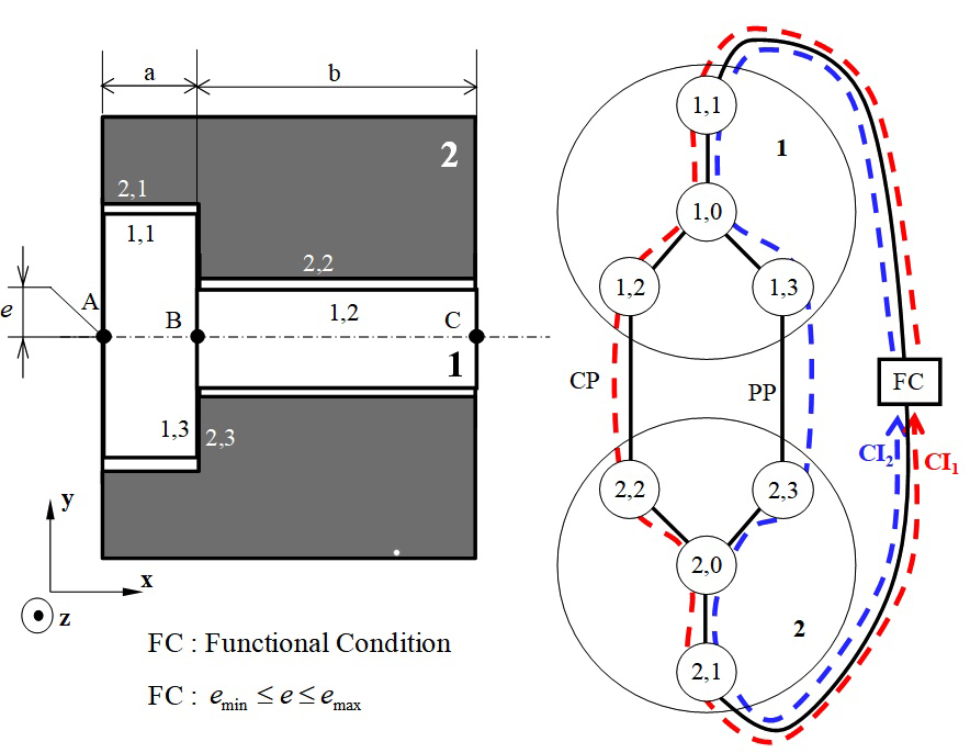
Formalising the topological structure of a mechanism may be based on a contact graph with one connected component on which the dimension chains35 can be visualised. Figure 4, based on Figure 3, is a graphic representation of the mechanism consisting of a shaft labelled 1 and housing labelled 2. The shaft is represented by a large circle and the three surfaces 1,1, 1,2 and 1,3 are small circles. All the nominal surfaces of the shaft are represented in a single small circle, called 1,0, representing a marker associated to the nominal model of part 1.2 The edge linking surface 1,1 to vertex 1,0 represents situation deviations for surface 1,1 in relation to its nominal surface. The edges that link together two surfaces belonging to two different parts represent the joints. For example, the edge that links surface 1,2 to surface 2,2 represents the cylindrical pair joint (label CP) between surfaces 1,2 and 2,2 while the edge linking surface 1,3 to 2,3 represents the planar pair joint (label PP). The features of these two joints are described in paragraph 2.1.2 and are shown in Figure 3.
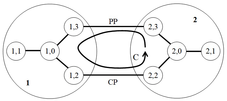
Figure 4 Graph representation.

We searched for independent cycles in order to determine which equations guaranteed that a mechanism can exist, i.e. that it can be assembled. The number of independent cycles is the cyclomatic number μ MathType@MTEF@5@5@+= feaagKart1ev2aqatCvAUfeBSjuyZL2yd9gzLbvyNv2CaerbuLwBLn hiov2DGi1BTfMBaeXatLxBI9gBaerbd9wDYLwzYbItLDharqqtubsr 4rNCHbGeaGqiVu0Je9sqqrpepC0xbbL8F4rqqrFfpeea0xe9Lq=Jc9 vqaqpepm0xbba9pwe9Q8fs0=yqaqpepae9pg0FirpepeKkFr0xfr=x fr=xb9adbaqaaeGaciGaaiaabeqaamaabaabaaGcbaqcLbsacqaH8o qBaaa@383C@ of the graph. In a graph with one connected component, μ MathType@MTEF@5@5@+= feaagKart1ev2aqatCvAUfeBSjuyZL2yd9gzLbvyNv2CaerbuLwBLn hiov2DGi1BTfMBaeXatLxBI9gBaerbd9wDYLwzYbItLDharqqtubsr 4rNCHbGeaGqiVu0Je9sqqrpepC0xbbL8F4rqqrFfpeea0xe9Lq=Jc9 vqaqpepm0xbba9pwe9Q8fs0=yqaqpepae9pg0FirpepeKkFr0xfr=x fr=xb9adbaqaaeGaciGaaiaabeqaamaabaabaaGcbaqcLbsacqaH8o qBaaa@383C@ is defined as follows:

μ=ev+1 with: e: number of edges of the graph v: number of vertices of the graph MathType@MTEF@5@5@+= feaagKart1ev2aqatCvAUfeBSjuyZL2yd9gzLbvyNv2CaerbuLwBLn hiov2DGi1BTfMBaeXatLxBI9gBaerbd9wDYLwzYbItLDharqqtubsr 4rNCHbGeaGqiVu0Je9sqqrpepC0xbbL8F4rqqrFfpeea0xe9Lq=Jc9 vqaqpepm0xbba9pwe9Q8fs0=yqaqpepae9pg0FirpepeKkFr0xfr=x fr=xb9adbaqaaeGaciGaaiaabeqaamaabaabaaGceaqabeaajugibi abeY7aTjabg2da9iaadwgacqGHsislcaWG2bGaey4kaSIaaGymaaGc baqcLbsacaqG3bGaaeyAaiaabshacaqGObGaaeOoaaGcbaqcLbsaca WGLbGaaeOoaiaabccacaqGUbGaaeyDaiaab2gacaqGIbGaaeyzaiaa bkhacaqGGaGaae4BaiaabAgacaqGGaGaaeyzaiaabsgacaqGNbGaae yzaiaabohacaqGGaGaae4BaiaabAgacaqGGaGaaeiDaiaabIgacaqG LbGaaeiiaiaabEgacaqGYbGaaeyyaiaabchacaqGObaakeaajugibi aadAhacaqG6aGaaeiiaiaab6gacaqG1bGaaeyBaiaabkgacaqGLbGa aeOCaiaabccacaqGVbGaaeOzaiaabccacaqG2bGaaeyzaiaabkhaca qG0bGaaeyAaiaabogacaqGLbGaae4CaiaabccacaqGVbGaaeOzaiaa bccacaqG0bGaaeiAaiaabwgacaqGGaGaae4zaiaabkhacaqGHbGaae iCaiaabIgaaaaa@7C99@ (12)

In our example:

μ=88+1=1 MathType@MTEF@5@5@+= feaagKart1ev2aqatCvAUfeBSjuyZL2yd9gzLbvyNv2CaerbuLwBLn hiov2DGi1BTfMBaeXatLxBI9gBaerbd9wDYLwzYbItLDharqqtubsr 4rNCHbGeaGqiVu0Je9sqqrpepC0xbbL8F4rqqrFfpeea0xe9Lq=Jc9 vqaqpepm0xbba9pwe9Q8fs0=yqaqpepae9pg0FirpepeKkFr0xfr=x fr=xb9adbaqaaeGaciGaaiaabeqaamaabaabaaGcbaqcLbsacqaH8o qBcqGH9aqpcaaI4aGaeyOeI0IaaGioaiabgUcaRiaaigdacqGH9aqp caaIXaaaaa@3F11@ (13)

For each cycle closure,36 considers that the condition of interchange ability can be verified if the sum of the deviation hulls, written [ E i,j/i,k ] MathType@MTEF@5@5@+= feaagKart1ev2aaatCvAUfeBSjuyZL2yd9gzLbvyNv2CaerbuLwBLn hiov2DGi1BTfMBaeXatLxBI9gBaerbd9wDYLwzYbItLDharqqtubsr 4rNCHbGeaGqiVu0Je9sqqrpepC0xbbL8F4rqqrFfpeea0xe9Lq=Jc9 vqaqpepm0xbba9pwe9Q8fs0=yqaqpepae9pg0FirpepeKkFr0xfr=x fr=xb9adbaqaaeGaciGaaiaabaqaamaabaabaaGcbaqcfa4aamWaaO qaaKqzGeGaaeyraKqbaoaaDaaaleaajugWaiaadMgacaGGSaGaamOA aiaac+cacaWGPbGaaiilaiaadUgaaSqaaaaaaOGaay5waiaaw2faaa aa@41A2@ , is included in the sum of the clearance hulls, written [ J i,j/u,v ] MathType@MTEF@5@5@+= feaagKart1ev2aaatCvAUfeBSjuyZL2yd9gzLbvyNv2CaerbuLwBLn hiov2DGi1BTfMBaeXatLxBI9gBaerbd9wDYLwzYbItLDharqqtubsr 4rNCHbGeaGqiVu0Je9sqqrpepC0xbbL8F4rqqrFfpeea0xe9Lq=Jc9 vqaqpepm0xbba9pwe9Q8fs0=yqaqpepae9pg0FirpepeKkFr0xfr=x fr=xb9adbaqaaeGaciGaaiaabaqaamaabaabaaGcbaqcfa4aamWaaO qaaKqzGeGaaeOsaKqbaoaaDaaaleaajugWaiaadMgacaGGSaGaamOA aiaac+cacaWG1bGaaiilaiaadAhaaSqaaaaaaOGaay5waiaaw2faaa aa@41BE@ . This condition guarantees assembly in the worst case, thus in our example:

( [ E 2,2/2,3 ]+[ E 1,3/1,2 ] )( [ J 1,2/2,2 min ]+[ J 2,3/1,3 ] ) MathType@MTEF@5@5@+= feaagKart1ev2aaatCvAUfeBSjuyZL2yd9gzLbvyNv2CaerbuLwBLn hiov2DGi1BTfMBaeXatLxBI9gBaerbd9wDYLwzYbItLDharqqtubsr 4rNCHbGeaGqiVu0Je9sqqrpepC0xbbL8F4rqqrFfpeea0xe9Lq=Jc9 vqaqpepm0xbba9pwe9Q8fs0=yqaqpepae9pg0FirpepeKkFr0xfr=x fr=xb9adbaqaaeGaciGaaiaabaqaamaabaabaaGcbaqcfa4aaeWaaO qaaKqbaoaadmaakeaajugibiaabweajuaGdaWgaaWcbaqcLbmacaaI YaGaaiilaiaaikdacaGGVaGaaGOmaiaacYcacaaIZaaaleqaaaGcca GLBbGaayzxaaqcLbsacqGHRaWkjuaGdaWadaGcbaqcLbsacaqGfbqc fa4aaSbaaSqaaKqzadGaaGymaiaacYcacaaIZaGaai4laiaaigdaca GGSaGaaGOmaaWcbeaaaOGaay5waiaaw2faaaGaayjkaiaawMcaaKqz GeGaeyOHI0Ccfa4aaeWaaOqaaKqbaoaadmaakeaajugibiaabQeaju aGdaqhaaWcbaqcLbmacaaIXaGaaiilaiaaikdacaGGVaGaaGOmaiaa cYcacaaIYaaaleaajugWaiGac2gacaGGPbGaaiOBaaaaaOGaay5wai aaw2faaKqzGeGaey4kaSscfa4aamWaaOqaaKqzGeGaaeOsaKqbaoaa BaaaleaajugWaiaaikdacaGGSaGaaG4maiaac+cacaaIXaGaaiilai aaiodaaSqabaaakiaawUfacaGLDbaaaiaawIcacaGLPaaaaaa@6F38@ (14)

In our case, condition (14) which is formalised by the hulls can be transposed by operations on polytopes. D i,j/u,v c,min MathType@MTEF@5@5@+= feaagKart1ev2aaatCvAUfeBSjuyZL2yd9gzLbvyNv2CaerbuLwBLn hiov2DGi1BTfMBaeXatLxBI9gBaerbd9wDYLwzYbItLDharqqtubsr 4rNCHbGeaGqiVu0Je9sqqrpepC0xbbL8F4rqqrFfpeea0xe9Lq=Jc9 vqaqpepm0xbba9pwe9Q8fs0=yqaqpepae9pg0FirpepeKkFr0xfr=x fr=xb9adbaqaaeGaciGaaiaabaqaamaabaabaaGcbaWefv3ySLgzgj xyRrxDYbqeguuDJXwAKbIrYf2A0vNCaGqbaKqzGeGae83aWtucfa4a a0baaSqaaKqzadGaamyAaiaacYcacaWGQbGaai4laiaadwhacaGGSa GaamODaaWcbaqcLbmacaqGJbGaaeilaiaab2gacaqGPbGaaeOBaaaa aaa@506A@ represents the contact polytope in the minimum clearance configuration that corresponds to the most unfavourable case for an assembly condition.

( D 2,2/2,3 g + D 1,3/1,2 g )( D 1,2/2,2 c,min + D 2,3/1,3 c ) MathType@MTEF@5@5@+= feaagKart1ev2aaatCvAUfeBSjuyZL2yd9gzLbvyNv2CaerbuLwBLn hiov2DGi1BTfMBaeXatLxBI9gBaerbd9wDYLwzYbItLDharqqtubsr 4rNCHbGeaGqiVu0Je9sqqrpepC0xbbL8F4rqqrFfpeea0xe9Lq=Jc9 vqaqpepm0xbba9pwe9Q8fs0=yqaqpepae9pg0FirpepeKkFr0xfr=x fr=xb9adbaqaaeGaciGaaiaabaqaamaabaabaaGcbaqcfa4aaeWaaO qaamrr1ngBPrMrYf2A0vNCaeHbfv3ySLgzGyKCHTgD1jhaiuaajugi biab=na8eLqbaoaaDaaaleaajugWaiaaikdacaGGSaGaaGOmaiaac+ cacaaIYaGaaiilaiaaiodaaSqaaKqzadGaae4zaaaajugibiabgUca Riab=na8eLqbaoaaDaaaleaajugWaiaaigdacaGGSaGaaG4maiaac+ cacaaIXaGaaiilaiaaikdaaSqaaKqzadGaae4zaaaaaOGaayjkaiaa wMcaaKqzGeGaeyOHI0Ccfa4aaeWaaOqaaKqzGeGae83aWtucfa4aa0 baaSqaaKqzadGaaGymaiaacYcacaaIYaGaai4laiaaikdacaGGSaGa aGOmaaWcbaqcLbmacaqGJbGaaeilaiaab2gacaqGPbGaaeOBaaaaju gibiabgUcaRiab=na8eLqbaoaaDaaaleaajugWaiaaikdacaGGSaGa aG4maiaac+cacaaIXaGaaiilaiaaiodaaSqaaKqzadGaae4yaaaaaO GaayjkaiaawMcaaaaa@7A3C@ (15)

Figure 5 shows how the Minkowski sum of the two contact polytopes is determined, where polytope D 1,2/2,2 c,min MathType@MTEF@5@5@+= feaagKart1ev2aaatCvAUfeBSjuyZL2yd9gzLbvyNv2CaerbuLwBLn hiov2DGi1BTfMBaeXatLxBI9gBaerbd9wDYLwzYbItLDharqqtubsr 4rNCHbGeaGqiVu0Je9sqqrpepC0xbbL8F4rqqrFfpeea0xe9Lq=Jc9 vqaqpepm0xbba9pwe9Q8fs0=yqaqpepae9pg0FirpepeKkFr0xfr=x fr=xb9adbaqaaeGaciGaaiaabaqaamaabaabaaGcbaWefv3ySLgzgj xyRrxDYbqeguuDJXwAKbIrYf2A0vNCaGqbaKqzGeGae83aWtucfa4a a0baaSqaaKqzadGaaGymaiaacYcacaaIYaGaai4laiaaikdacaGGSa GaaGOmaaWcbaqcLbmacaqGJbGaaeilaiaab2gacaqGPbGaaeOBaaaa aaa@4F87@ characterises the CP joint in the minimum clearance configuration. The two geometric polytopes D 1,2/1,3 g MathType@MTEF@5@5@+= feaagKart1ev2aaatCvAUfeBSjuyZL2yd9gzLbvyNv2CaerbuLwBLn hiov2DGi1BTfMBaeXatLxBI9gBaerbd9wDYLwzYbItLDharqqtubsr 4rNCHbGeaGqiVu0Je9sqqrpepC0xbbL8F4rqqrFfpeea0xe9Lq=Jc9 vqaqpepm0xbba9pwe9Q8fs0=yqaqpepae9pg0FirpepeKkFr0xfr=x fr=xb9adbaqaaeGaciGaaiaabaqaamaabaabaaGcbaWefv3ySLgzgj xyRrxDYbqeguuDJXwAKbIrYf2A0vNCaGqbaKqzGeGae83aWtucfa4a a0baaSqaaKqzadGaaGymaiaacYcacaaIYaGaai4laiaaigdacaGGSa GaaG4maaWcbaqcLbmacaqGNbaaaaaa@4C0F@ and D 2,2/2,3 g MathType@MTEF@5@5@+= feaagKart1ev2aaatCvAUfeBSjuyZL2yd9gzLbvyNv2CaerbuLwBLn hiov2DGi1BTfMBaeXatLxBI9gBaerbd9wDYLwzYbItLDharqqtubsr 4rNCHbGeaGqiVu0Je9sqqrpepC0xbbL8F4rqqrFfpeea0xe9Lq=Jc9 vqaqpepm0xbba9pwe9Q8fs0=yqaqpepae9pg0FirpepeKkFr0xfr=x fr=xb9adbaqaaeGaciGaaiaabaqaamaabaabaaGcbaWefv3ySLgzgj xyRrxDYbqeguuDJXwAKbIrYf2A0vNCaGqbaKqzGeGae83aWtucfa4a a0baaSqaaKqzadGaaGOmaiaacYcacaaIYaGaai4laiaaikdacaGGSa GaaG4maaWcbaqcLbmacaqGNbaaaaaa@4C11@ correspond to two perpendicularity specifications on parts 1 and 2 respectively (see Figure 6).
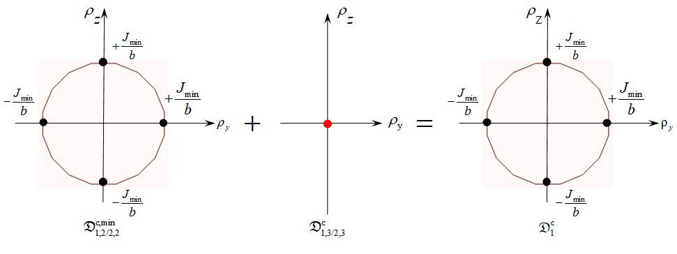
Figure 5 Minkowski sum of contact polytopes.
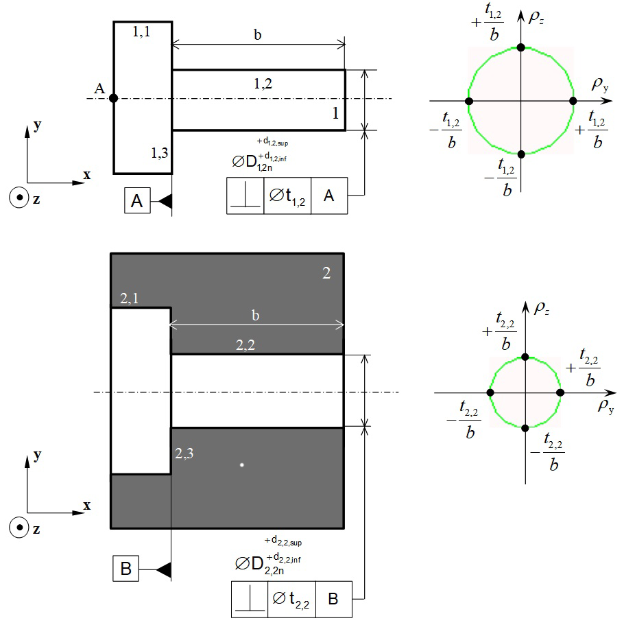
Figure 6 Perpendicularity specifications modelled by geometric polytopes.

Finally, Figure 7 illustrates equation (15) where the sum of geometric polytopes must be inside the sum of contact polytopes in a cycle. From this, we deduce the condition for assembling the system in the worst case scenario, as defined in the following equation:

t 1,2 b + t 2,2 b J min b MathType@MTEF@5@5@+= feaagKart1ev2aaatCvAUfeBSjuyZL2yd9gzLbvyNv2CaerbuLwBLn hiov2DGi1BTfMBaeXatLxBI9gBaerbd9wDYLwzYbItLDharqqtubsr 4rNCHbGeaGqiVu0Je9sqqrpepC0xbbL8F4rqqrFfpeea0xe9Lq=Jc9 vqaqpepm0xbba9pwe9Q8fs0=yqaqpepae9pg0FirpepeKkFr0xfr=x fr=xb9adbaqaaeGaciGaaiaabeqaamaabaabaaGcbaqcfaieeaaaaa aaa40BPjhapeWaaSaaaOqaaKqzGeGaamiDaKqbaoaaBaaaleaajugW aiaaigdacaGGSaGaaGOmaaWcbeaaaOqaaKqzGeGaamOyaaaacqGHRa WkjuaGdaWcaaGcbaqcLbsacaWG0bqcfa4aaSbaaSqaaKqzadGaaGOm aiaacYcacaaIYaaaleqaaaGcbaqcLbsacaWGIbaaaiabgsMiJMqbao aalaaakeaajugibiaadQeajuaGdaWgaaWcbaqcLbmaciGGTbGaaiyA aiaac6gaaSqabaaakeaajugibiaadkgaaaaaaa@5229@ (16)

Figure 7 Inclusion of a sum of geometric polytopes inside a sum of contact polytopes in a cycle.

Simulation of respecting a functional condition

A functional condition (or requirement) is a condition placed on a functional characteristic of position or orientation between two surfaces, which are usually on different parts, and which are not potentially in contact. Figure 8 illustrates the example presented above. Let us suppose that a functional condition FC has to be respected which limits the relative position of surfaces 1,1 and 2,1. In the diagram this is represented in a rectangle labelled FC on an edge linking surfaces 1,1 and 2,1. This example shows a condition of coaxiality being modelled in a unidirectional functional condition. The functional condition FC limits the displacement of point A on the axis of surface 1,1 in relation to the axis of surface 2,1 along axis y:

e min e e max   with  e= ε A-1,3/2,3 .y MathType@MTEF@5@5@+= feaagKart1ev2aqatCvAUfeBSjuyZL2yd9gzLbvyNv2CaerbuLwBLn hiov2DGi1BTfMBaeXatLxBI9gBaerbd9wDYLwzYbItLDharqqtubsr 4rNCHbGeaGqiVu0Je9sqqrpepC0xbbL8F4rqqrFfpeea0xe9Lq=Jc9 vqaqpepm0xbba9pwe9Q8fs0=yqaqpepae9pg0FirpepeKkFr0xfr=x fr=xb9adbaqaaeGaciGaaiaabeqaamaabaabaaGcbaqcLbsaciGGLb qcfa4aaSbaaSqaaKqzadGaciyBaiaacMgacaGGUbaaleqaaKqzGeGa eyizImQaamyzaiabgsMiJkGacwgajuaGdaWgaaWcbaqcLbmaciGGTb GaaiyyaiaacIhaaSqabaqcLbsacaqGGaGaaeiiaiaabEhacaqGPbGa aeiDaiaabIgacaqGGaGaaeiiaiaadwgacqGH9aqpcaWH1oqcfa4aaS baaSqaaKqzadGaaeyqaiaab2cacaaIXaGaaiilaiaaiodacaGGVaGa aGOmaiaacYcacaaIZaaaleqaaKqzGeGaaiOlaiaahMhaaaa@5B8D@ (17)

Equation (17) represents two halfspaces of dimension 1, whose intersection defines the functional polytope D 1,1/2,1 f MathType@MTEF@5@5@+= feaagKart1ev2aaatCvAUfeBSjuyZL2yd9gzLbvyNv2CaerbuLwBLn hiov2DGi1BTfMBaeXatLxBI9gBaerbd9wDYLwzYbItLDharqqtubsr 4rNCHbGeaGqiVu0Je9sqqrpepC0xbbL8F4rqqrFfpeea0xe9Lq=Jc9 vqaqpepm0xbba9pwe9Q8fs0=yqaqpepae9pg0FirpepeKkFr0xfr=x fr=xb9adbaqaaeGaciGaaiaabaqaamaabaabaaGcbaWefv3ySLgzgj xyRrxDYbqeguuDJXwAKbIrYf2A0vNCaGqbaKqzGeGae83aWtucfa4a a0baaSqaaKqzadGaaGymaiaacYcacaaIXaGaai4laiaabkdacaqGSa GaaeymaaWcbaqcLbmacaqGMbaaaaaa@4BFD@ characterising the functional condition FC. The functional condition FC depends on two cycles C1and C2: see Figure 8. For the FC to be respected, the intersection of the two geometric polytopes representing the deviations between surfaces 1,1 and 2,1 by C1 and C2 respectively must be included in the functional polytope D 1,1/2,1 f MathType@MTEF@5@5@+= feaagKart1ev2aaatCvAUfeBSjuyZL2yd9gzLbvyNv2CaerbuLwBLn hiov2DGi1BTfMBaeXatLxBI9gBaerbd9wDYLwzYbItLDharqqtubsr 4rNCHbGeaGqiVu0Je9sqqrpepC0xbbL8F4rqqrFfpeea0xe9Lq=Jc9 vqaqpepm0xbba9pwe9Q8fs0=yqaqpepae9pg0FirpepeKkFr0xfr=x fr=xb9adbaqaaeGaciGaaiaabaqaamaabaabaaGcbaWefv3ySLgzgj xyRrxDYbqeguuDJXwAKbIrYf2A0vNCaGqbaKqzGeGae83aWtucfa4a a0baaSqaaKqzadGaaGymaiaacYcacaaIXaGaai4laiaabkdacaqGSa GaaeymaaWcbaqcLbmacaqGMbaaaaaa@4BFD@ :13

( D 1,1/2,1 1 D 1,1/2,1 2 ) D 1,1/2,1 f with : D 1,1/2,1 1  polytope corresponding to  C 1 D 1,1/2,1 2  polytope corresponding to  C 2 MathType@MTEF@5@5@+= feaagKart1ev2aaatCvAUfeBSjuyZL2yd9gzLbvyNv2CaerbuLwBLn hiov2DGi1BTfMBaeXatLxBI9gBaerbd9wDYLwzYbItLDharqqtubsr 4rNCHbGeaGqiVu0Je9sqqrpepC0xbbL8F4rqqrFfpeea0xe9Lq=Jc9 vqaqpepm0xbba9pwe9Q8fs0=yqaqpepae9pg0FirpepeKkFr0xfr=x fr=xb9adbaqaaeGaciGaaiaabaqaamaabaabaaGceaqabeaajuaGda qadaGcbaWefv3ySLgzgjxyRrxDYbqeguuDJXwAKbIrYf2A0vNCaGqb aKqzGeGae83aWtucfa4aa0baaSqaaKqzadGaaGymaiaacYcacaaIXa Gaai4laiaabkdacaqGSaGaaeymaaWcbaqcLbmacaqGXaaaaKqzGeGa eyykICSae83aWtucfa4aa0baaSqaaKqzadGaaGymaiaacYcacaaIXa Gaai4laiaabkdacaqGSaGaaeymaaWcbaqcLbmacaqGYaaaaaGccaGL OaGaayzkaaqcLbsacqGHgksZcqWFdaprjuaGdaqhaaWcbaqcLbmaca aIXaGaaiilaiaaigdacaGGVaGaaeOmaiaabYcacaqGXaaaleaajugW aiaabAgaaaaakeaajugibiaabEhacaqGPbGaaeiDaiaabIgacaqGGa GaaeOoaaGcbaqcLbsacqWFdaprjuaGdaqhaaWcbaqcLbmacaaIXaGa aiilaiaaigdacaGGVaGaaeOmaiaabYcacaqGXaaaleaajugWaiaabg daaaqcLbsacaqGGaGaaeiCaiaab+gacaqGSbGaaeyEaiaabshacaqG VbGaaeiCaiaabwgacaqGGaGaae4yaiaab+gacaqGYbGaaeOCaiaabw gacaqGZbGaaeiCaiaab+gacaqGUbGaaeizaiaabMgacaqGUbGaae4z aiaabccacaqG0bGaae4BaiaabccacaWGdbqcfa4aaSbaaSqaaKqzad GaaGymaaWcbeaaaOqaaKqzGeGae83aWtucfa4aa0baaSqaaKqzadGa aGymaiaacYcacaaIXaGaai4laiaabkdacaqGSaGaaeymaaWcbaqcLb macaqGYaaaaKqzGeGaaeiiaiaabchacaqGVbGaaeiBaiaabMhacaqG 0bGaae4BaiaabchacaqGLbGaaeiiaiaabogacaqGVbGaaeOCaiaabk hacaqGLbGaae4CaiaabchacaqGVbGaaeOBaiaabsgacaqGPbGaaeOB aiaabEgacaqGGaGaaeiDaiaab+gacaqGGaGaam4qaKqbaoaaBaaale aajugWaiaaikdaaSqabaaaaaa@BC54@ (18)

Figure 8 Cycles influent on the Functional Condition FC.

The position of surface 1,1 (cylinder) can be controlled in relation to surfaces 1,3 (primary plane) and 1,2 (secondary cylinder) by defining a location specification using ISO standards:4 see Figure 9 and Figure 10. The position of surface 2,1 in relation to 2,3 and 2,2 can be defined in the same way by a location specification: see Figure 9 and Figure 10. Finally, the geometric polytope characterising the deviations of surface 1,1 in relation to surface 2,1 is given in:

D 1,1/2,1 1 D 1,1/2,1 2 = D 1,1/1,3-1,2 g +( D 1,2/2,2 c D 1,3/2,3 c )+ D 2,32,2/2,1 g with: D 1,1/2,1 1 = D 1,1/1,3-1,2 g + D 1,3/2,3 c + D 2,32,2/2,1 g D 1,1/2,1 2 = D 1,1/1,3-1,2 g + D 1,2/2,2 c + D 2,32,2/2,1 g MathType@MTEF@5@5@+= feaagKart1ev2aaatCvAUfeBSjuyZL2yd9gzLbvyNv2CaerbuLwBLn hiov2DGi1BTfMBaeXatLxBI9gBaerbd9wDYLwzYbItLDharqqtubsr 4rNCHbGeaGqiVu0Je9sqqrpepC0xbbL8F4rqqrFfpeea0xe9Lq=Jc9 vqaqpepm0xbba9pwe9Q8fs0=yqaqpepae9pg0FirpepeKkFr0xfr=x fr=xb9adbaqaaeGaciGaaiaabaqaamaabaabaaGceaqabeaatuuDJX wAKzKCHTgD1jharyqr1ngBPrgigjxyRrxDYbacfaqcLbsacqWFdapr juaGdaqhaaWcbaqcLbmacaaIXaGaaiilaiaaigdacaGGVaGaaeOmai aabYcacaqGXaaaleaajugWaiaabgdaaaqcLbsacqGHPiYXcqWFdapr juaGdaqhaaWcbaqcLbmacaaIXaGaaiilaiaaigdacaGGVaGaaeOmai aabYcacaqGXaaaleaajugWaiaabkdaaaqcLbsacqGH9aqpcqWFdapr juaGdaqhaaWcbaqcLbmacaaIXaGaaiilaiaaigdacaGGVaGaaeymai aabYcacaqGZaGaaeylaiaabgdacaqGSaGaaeOmaaWcbaqcLbmacaqG NbaaaKqzGeGae83kaSscfa4aaeWaaOqaaKqzGeGae83aWtucfa4aa0 baaSqaaKqzadGaaGymaiaacYcacaaIYaGaai4laiaabkdacaqGSaGa aeOmaaWcbaqcLbmacaqGJbaaaKqzGeGaeyykICSae83aWtucfa4aa0 baaSqaaKqzadGaaGymaiaacYcacaaIZaGaai4laiaabkdacaqGSaGa ae4maaWcbaqcLbmacaqGJbaaaaGccaGLOaGaayzkaaqcLbsacqWFRa WkcqWFdaprjuaGdaqhaaWcbaqcLbmacaaIYaGaaiilaiaaiodacqGH sislcaaIYaGaaiilaiaaikdacaGGVaGaaeOmaiaabYcacaqGXaaale aajugWaiaabEgaaaaakeaajugibiaabEhacaqGPbGaaeiDaiaabIga caqG6aaakeaajugibiab=na8eLqbaoaaDaaaleaajugWaiaaigdaca GGSaGaaGymaiaac+cacaqGYaGaaeilaiaabgdaaSqaaKqzadGaaeym aaaajugibiabg2da9iab=na8eLqbaoaaDaaaleaajugWaiaaigdaca GGSaGaaGymaiaac+cacaqGXaGaaeilaiaabodacaqGTaGaaeymaiaa bYcacaqGYaaaleaajugWaiaabEgaaaqcLbsacqWFRaWkcqWFdaprju aGdaqhaaWcbaqcLbmacaaIXaGaaiilaiaaiodacaGGVaGaaeOmaiaa bYcacaqGZaaaleaajugWaiaabogaaaqcLbsacqWFRaWkcqWFdaprju aGdaqhaaWcbaqcLbmacaaIYaGaaiilaiaaiodacqGHsislcaaIYaGa aiilaiaaikdacaGGVaGaaeOmaiaabYcacaqGXaaaleaajugWaiaabE gaaaaakeaajugibiab=na8eLqbaoaaDaaaleaajugWaiaaigdacaGG SaGaaGymaiaac+cacaqGYaGaaeilaiaabgdaaSqaaKqzadGaaeOmaa aajugibiabg2da9iab=na8eLqbaoaaDaaaleaajugWaiaaigdacaGG SaGaaGymaiaac+cacaqGXaGaaeilaiaabodacaqGTaGaaeymaiaabY cacaqGYaaaleaajugWaiaabEgaaaqcLbsacqWFRaWkcqWFdaprjuaG daqhaaWcbaqcLbmacaaIXaGaaiilaiaaikdacaGGVaGaaeOmaiaabY cacaqGYaaaleaajugWaiaabogaaaqcLbsacqWFRaWkcqWFdaprjuaG daqhaaWcbaqcLbmacaaIYaGaaiilaiaaiodacqGHsislcaaIYaGaai ilaiaaikdacaGGVaGaaeOmaiaabYcacaqGXaaaleaajugWaiaabEga aaaaaaa@02D4@ (19)

Figure 9 Graph representation of geometric specifications ensuring respect of the Functional Condition FC.
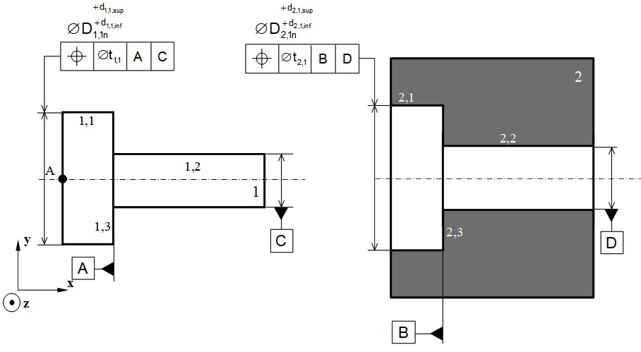
Figure 10 ISO representation of geometric specifications ensuring respect of the Functional Condition FC.

From this we deduce that respecting the functional condition FC can be written:

D 1,1/1,3-1,2 g +( D 1,2/2,2 c D 1,3/2,3 c )+ D 2,32,2/2,1 g D 1,1/2,1 f MathType@MTEF@5@5@+= feaagKart1ev2aaatCvAUfeBSjuyZL2yd9gzLbvyNv2CaerbuLwBLn hiov2DGi1BTfMBaeXatLxBI9gBaerbd9wDYLwzYbItLDharqqtubsr 4rNCHbGeaGqiVu0Je9sqqrpepC0xbbL8F4rqqrFfpeea0xe9Lq=Jc9 vqaqpepm0xbba9pwe9Q8fs0=yqaqpepae9pg0FirpepeKkFr0xfr=x fr=xb9adbaqaaeGaciGaaiaabaqaamaabaabaaGcbaWefv3ySLgzgj xyRrxDYbqeguuDJXwAKbIrYf2A0vNCaGqbaKqzGeGae83aWtucfa4a a0baaSqaaKqzadGaaGymaiaacYcacaaIXaGaai4laiaabgdacaqGSa Gaae4maiaab2cacaqGXaGaaeilaiaabkdaaSqaaKqzadGaae4zaaaa jugibiab=TcaRKqbaoaabmaakeaajugibiab=na8eLqbaoaaDaaale aajugWaiaaigdacaGGSaGaaGOmaiaac+cacaqGYaGaaeilaiaabkda aSqaaKqzadGaae4yaaaajugibiabgMIihlab=na8eLqbaoaaDaaale aajugWaiaaigdacaGGSaGaaG4maiaac+cacaqGYaGaaeilaiaaboda aSqaaKqzadGaae4yaaaaaOGaayjkaiaawMcaaKqzGeGae83kaSIae8 3aWtucfa4aa0baaSqaaKqzadGaaGOmaiaacYcacaaIZaGaeyOeI0Ia aGOmaiaacYcacaaIYaGaai4laiaabkdacaqGSaGaaeymaaWcbaqcLb macaqGNbaaaKqzGeGaeyOHI0Sae83aWtucfa4aa0baaSqaaKqzadGa aGymaiaacYcacaaIXaGaai4laiaabkdacaqGSaGaaeymaaWcbaqcLb macaqGMbaaaaaa@870B@ (20)

Let us suppose:

D 1,1/2,1 = D 1,1/1,3-1,2 g +( D 1,2/2,2 c D 1,3/2,3 c )+ D 2,32,2/2,1 g MathType@MTEF@5@5@+= feaagKart1ev2aaatCvAUfeBSjuyZL2yd9gzLbvyNv2CaerbuLwBLn hiov2DGi1BTfMBaeXatLxBI9gBaerbd9wDYLwzYbItLDharqqtubsr 4rNCHbGeaGqiVu0Je9sqqrpepC0xbbL8F4rqqrFfpeea0xe9Lq=Jc9 vqaqpepm0xbba9pwe9Q8fs0=yqaqpepae9pg0FirpepeKkFr0xfr=x fr=xb9adbaqaaeGaciGaaiaabaqaamaabaabaaGcbaWefv3ySLgzgj xyRrxDYbqeguuDJXwAKbIrYf2A0vNCaGqbaKqzGeGae83aWtucfa4a a0baaSqaaKqzadGaaGymaiaacYcacaaIXaGaai4laiaabkdacaqGSa GaaeymaaWcbaaaaKqzGeGaeyypa0Jae83aWtucfa4aa0baaSqaaKqz adGaaGymaiaacYcacaaIXaGaai4laiaabgdacaqGSaGaae4maiaab2 cacaqGXaGaaeilaiaabkdaaSqaaKqzadGaae4zaaaajugibiab=Tca RKqbaoaabmaakeaajugibiab=na8eLqbaoaaDaaaleaajugWaiaaig dacaGGSaGaaGOmaiaac+cacaqGYaGaaeilaiaabkdaaSqaaKqzadGa ae4yaaaajugibiabgMIihlab=na8eLqbaoaaDaaaleaajugWaiaaig dacaGGSaGaaG4maiaac+cacaqGYaGaaeilaiaabodaaSqaaKqzadGa ae4yaaaaaOGaayjkaiaawMcaaKqzGeGae83kaSIae83aWtucfa4aa0 baaSqaaKqzadGaaGOmaiaacYcacaaIZaGaeyOeI0IaaGOmaiaacYca caaIYaGaai4laiaabkdacaqGSaGaaeymaaWcbaqcLbmacaqGNbaaaa aa@83F9@ (21)

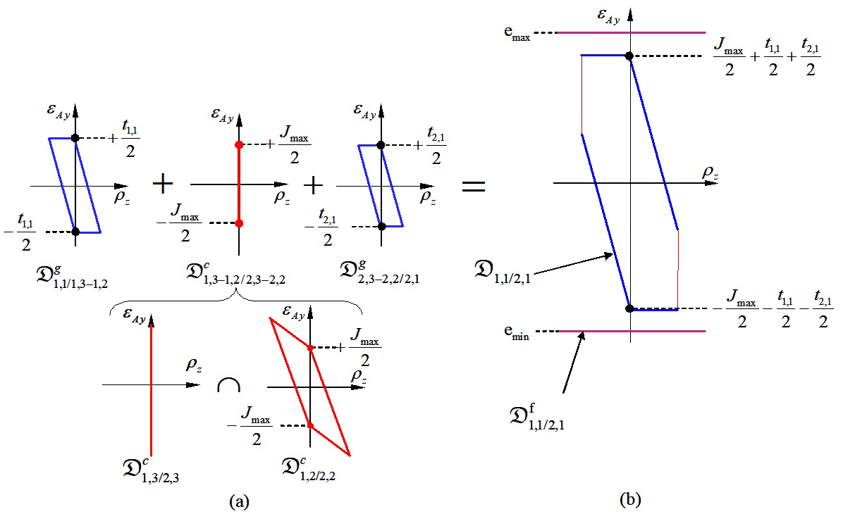
Figure 11a shows determining polytope D 1,1/2,1 MathType@MTEF@5@5@+= feaagKart1ev2aaatCvAUfeBSjuyZL2yd9gzLbvyNv2CaerbuLwBLn hiov2DGi1BTfMBaeXatLxBI9gBaerbd9wDYLwzYbItLDharqqtubsr 4rNCHbGeaGqiVu0Je9sqqrpepC0xbbL8F4rqqrFfpeea0xe9Lq=Jc9 vqaqpepm0xbba9pwe9Q8fs0=yqaqpepae9pg0FirpepeKkFr0xfr=x fr=xb9adbaqaaeGaciGaaiaabaqaamaabaabaaGcbaWefv3ySLgzgj xyRrxDYbqeguuDJXwAKbIrYf2A0vNCaGqbaKqzGeGae83aWtucfa4a a0baaSqaaKqzadGaaGymaiaacYcacaaIXaGaai4laiaabkdacaqGSa GaaeymaaWcbaaaaaaa@49E6@ using Minkwoski sums and an intersection. Figure 11b shows respecting the functional condition where the geometric polytope D 1,1/2,1 MathType@MTEF@5@5@+= feaagKart1ev2aaatCvAUfeBSjuyZL2yd9gzLbvyNv2CaerbuLwBLn hiov2DGi1BTfMBaeXatLxBI9gBaerbd9wDYLwzYbItLDharqqtubsr 4rNCHbGeaGqiVu0Je9sqqrpepC0xbbL8F4rqqrFfpeea0xe9Lq=Jc9 vqaqpepm0xbba9pwe9Q8fs0=yqaqpepae9pg0FirpepeKkFr0xfr=x fr=xb9adbaqaaeGaciGaaiaabaqaamaabaabaaGcbaWefv3ySLgzgj xyRrxDYbqeguuDJXwAKbIrYf2A0vNCaGqbaKqzGeGae83aWtucfa4a a0baaSqaaKqzadGaaGymaiaacYcacaaIXaGaai4laiaabkdacaqGSa GaaeymaaWcbaaaaaaa@49E6@ (of dimension 2) must be included inside polytope D 1,1/2,1 f MathType@MTEF@5@5@+= feaagKart1ev2aaatCvAUfeBSjuyZL2yd9gzLbvyNv2CaerbuLwBLn hiov2DGi1BTfMBaeXatLxBI9gBaerbd9wDYLwzYbItLDharqqtubsr 4rNCHbGeaGqiVu0Je9sqqrpepC0xbbL8F4rqqrFfpeea0xe9Lq=Jc9 vqaqpepm0xbba9pwe9Q8fs0=yqaqpepae9pg0FirpepeKkFr0xfr=x fr=xb9adbaqaaeGaciGaaiaabaqaamaabaabaaGcbaWefv3ySLgzgj xyRrxDYbqeguuDJXwAKbIrYf2A0vNCaGqbaKqzGeGae83aWtucfa4a a0baaSqaaKqzadGaaGymaiaacYcacaaIXaGaai4laiaabkdacaqGSa GaaeymaaWcbaqcLbmacaqGMbaaaaaa@4BFD@ (of dimension 1). Consequently, respect for the functional condition FC can be defined by the following equations in the worst of cases:

J 2 max 2 t 1,1 2 t 2,1 2 e min + J 2 max 2 + t 1,1 2 + t 2,1 2 e max MathType@MTEF@5@5@+= feaagKart1ev2aqatCvAUfeBSjuyZL2yd9gzLbvyNv2CaerbuLwBLn hiov2DGi1BTfMBaeXatLxBI9gBaerbd9wDYLwzYbItLDharqqtubsr 4rNCHbGeaGqiVu0Je9sqqrpepC0xbbL8F4rqqrFfpeea0xe9Lq=Jc9 vqaqpepm0xbba9pwe9Q8fs0=yqaqpepae9pg0FirpepeKkFr0xfr=x fr=xb9adbaqaaeGaciGaaiaabeqaamaabaabaaGceaqabeaajugiba bbaaaaaaaao9wAYbWdbiabgkHiTKqbaoaalaaakeaajugibiaadQea juaGdaqhaaWcbaqcLbmacaaIYaaaleaajugWaiGac2gacaGGHbGaai iEaaaaaOqaaKqzGeGaaGOmaaaacqGHsisljuaGdaWcaaGcbaqcLbsa caWG0bqcfa4aaSbaaSqaaKqzadGaaGymaiaacYcacaaIXaaaleqaaa GcbaqcLbsacaaIYaaaaiabgkHiTKqbaoaalaaakeaajugibiaadsha juaGdaWgaaWcbaqcLbmacaaIYaGaaiilaiaaigdaaSqabaaakeaaju gibiaaikdaaaGaeyyzImRaamyzaKqbaoaaBaaaleaajugWaiGac2ga caGGPbGaaiOBaaWcbeaaaOqaaKqzGeGaey4kaSscfa4aaSaaaOqaaK qzGeGaamOsaKqbaoaaDaaaleaajugWaiaaikdaaSqaaKqzadGaciyB aiaacggacaGG4baaaaGcbaqcLbsacaaIYaaaaiabgUcaRKqbaoaala aakeaajugibiaadshajuaGdaWgaaWcbaqcLbmacaaIXaGaaiilaiaa igdaaSqabaaakeaajugibiaaikdaaaGaey4kaSscfa4aaSaaaOqaaK qzGeGaamiDaKqbaoaaBaaaleaajugWaiaaikdacaGGSaGaaGymaaWc beaaaOqaaKqzGeGaaGOmaaaacqGHKjYOcaWGLbqcfa4aaSbaaSqaaK qzadGaciyBaiaacggacaGG4baaleqaaaaaaa@7FBE@ (22)

Figure 11 Respect of the Functional Condition FC by operations on polytopes.

Including thermo-mechanical strains in the geometrical variations

Description of the thermo-mechanical operating cycle of a system:

So that thermo-mechanical strains can be included in the geometric variations of the reference behaviour, several different behaviours are considered for each system studied:

  1. One reference behaviour,
  2. One or several thermo-mechanical behaviours.

A reference model is defined from the reference behaviour, where all the parts are at 20°C. This reference model is based on the hypotheses traditionally put forward in geometric tolerancing, and set out at the beginning of section 2. Thermo-mechanical behaviour corresponds to a particular operating point in the system where certain parts are subjected to thermo-mechanical constraints. Thermo-mechanical constraints on the parts cause strains, leading to situation, dimension and form deviations which must be considered when modelling geometric variations. The functioning of the system studied here over time is discretized into several different thermo-mechanical behaviours. No transitional state is considered. Next in section 3 we show how modelling particular thermo-mechanical behaviour with polytopes can be deduced from the model already defined for the reference behaviour.37

The following hypotheses are postulated:

  1. Invariance of the topological structure of the contact graph,
  2. Consideration of variations in the form and dimensions of the parts,
  3. No local strain on surfaces in contact.

Invariance of the topological structure of the contact graph means that there is no additional contact or any suppression of contact between two behaviours. In addition, each contact type remains the same: a cylindrical pair remains a cylindrical pair; a planar pair remains a planar pair, etc. However, the different parameters that characterise contact (minimal clearance, maximal clearance, nature of contact, etc.) may change. The thermo-mechanical behaviour of the system is presumed to be elastic; it is modelled in small strains and in small displacements.

Integration of thermo-mechanical strains on the parts in a free state

For each part, a thermo-mechanical simulation is carried out with finite elements in a free state. The purpose of a simulation is to determine geometric variations of thermo-mechanical origin in a part, while considering no contact stress with the surrounding parts. A method commonly used in tridimensional metrology26 assesses geometric variations in a part in a free state that are thermo-mechanical in origin. A deformed part is modelled by a finite number of points, each of which corresponds to a node in the mesh of the deformed part. An ideal surface (plane, cylinder, cone, etc.) is associated to the mesh nodes using the least squares criterion. Thus a plane surface is associated to the nodes of the deformation of a nominal plane surface; a cylindrical surface is associated to the nodes of the deformation of a nominal cylindrical surface, etc. It is thus possible to characterise the geometric deviations caused by thermo-mechanical strain between two associated surfaces, using a small displacement torsor from which a reduced polytope with a vertex of n MathType@MTEF@5@5@+= feaagKart1ev2aqatCvAUfeBSjuyZL2yd9gzLbvyNv2CaerbuLwBLn hiov2DGi1BTfMBaeXatLxBI9gBaerbd9wDYLwzYbItLDharqqtubsr 4rNCHbGeaGqiVu0Je9sqqrpepC0xbbL8F4rqqrFfpeea0xe9Lq=Jc9 vqaqpepm0xbba9pwe9Q8fs0=yqaqpepae9pg0FirpepeKkFr0xfr=x fr=xb9adbaqaaeGaciGaaiaabeqaamaabaabaaGcbaqcLbsaqqaaaa aaaaGtVLMCa8qacqWIDesOjuaGdaahaaWcbeqaaKqzadGaamOBaaaa aaa@3C8E@ can be deduced.

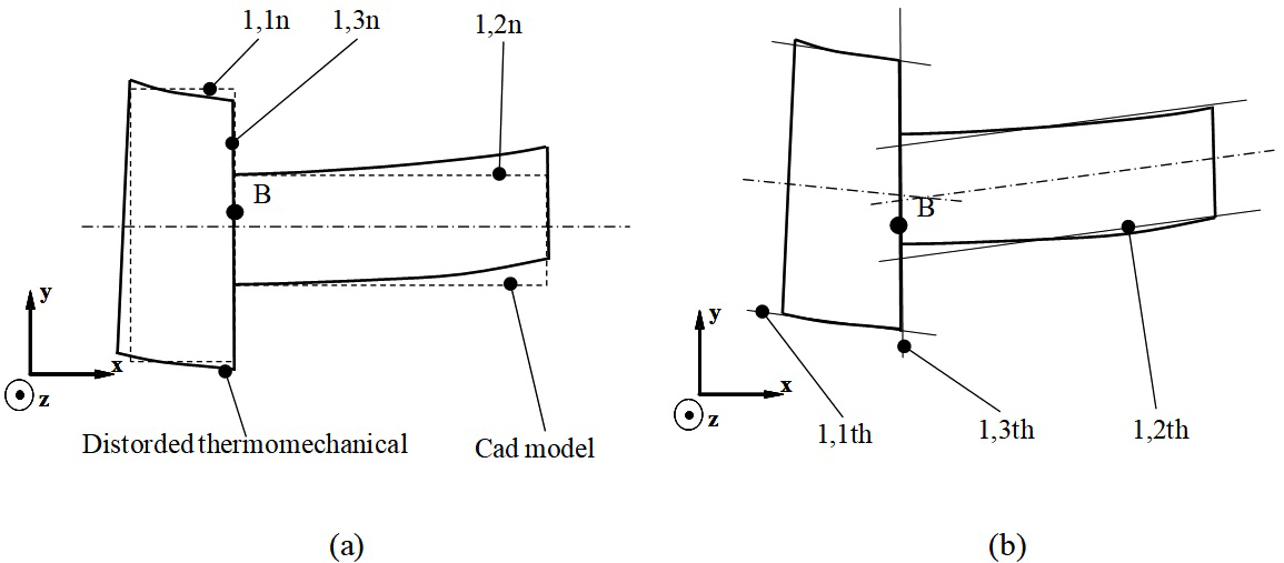
Let us consider part 1 shown in Figure 12: Figure 12a shows the nominal model of the part from which the deformation of the part subjected to thermo-mechanical strains is determined. Figure 12b shows the associations of two cylindrical surfaces 1,1th and 2,2th with deformations deduced from the nominal cylindrical surfaces 1,1n and 2,2n respectively. In the same way, the plane surface 1,3th is associated with the deformation deduced from the nominal plane surface 1,3n. The relative position of surfaces 1,3th and 1,2th can be expressed by the following equation, based on (3):

[ d 1,2th/1,3th ]=[ d 1,2th/1,2n ]+[ d 1,3n/1,3th ] MathType@MTEF@5@5@+= feaagKart1ev2aqatCvAUfeBSjuyZL2yd9gzLbvyNv2CaerbuLwBLn hiov2DGi1BTfMBaeXatLxBI9gBaerbd9wDYLwzYbItLDharqqtubsr 4rNCHbGeaGqiVu0Je9sqqrpepC0xbbL8F4rqqrFfpeea0xe9Lq=Jc9 vqaqpepm0xbba9pwe9Q8fs0=yqaqpepae9pg0FirpepeKkFr0xfr=x fr=xb9adbaqaaeGaciGaaiaabeqaamaabaabaaGcbaqcfaieeaaaaa aaa40BPjhapeWaamWaaOqaaKqzGeGaamizaKqbaoaaBaaaleaajugW aiaaigdacaGGSaGaaGOmaiaadshacaWGObGaai4laiaaigdacaGGSa GaaG4maiaadshacaWGObaaleqaaaGccaGLBbGaayzxaaqcLbsacqGH 9aqpjuaGdaWadaGcbaqcLbsacaWGKbqcfa4aaSbaaSqaaKqzadGaaG ymaiaacYcacaaIYaGaamiDaiaadIgacaGGVaGaaGymaiaacYcacaaI YaGaamOBaaWcbeaaaOGaay5waiaaw2faaKqzGeGaey4kaSscfa4aam WaaOqaaKqzGeGaamizaKqbaoaaBaaaleaajugWaiaaigdacaGGSaGa aG4maiaad6gacaGGVaGaaGymaiaacYcacaaIZaGaamiDaiaadIgaaS qabaaakiaawUfacaGLDbaaaaa@653A@ (23)

Figure 12 Characterisation of thermo-mechanical strains by geometric deviations defined by substituted surfaces.

In the base (x,y,z), we have:

[ d 1,2th/1,3th ]= B [ ρ 1,2th/1,3th ε B1,2th/1,3th ]with ρ 1,3th/1,2th [ 0 ρ 1,2th/1,3thy ρ 1,2th/1,3th z ]and ε B1,2th/1,3th =0 MathType@MTEF@5@5@+= feaagKart1ev2aqatCvAUfeBSjuyZL2yd9gzLbvyNv2CaerbuLwBLn hiov2DGi1BTfMBaeXatLxBI9gBaerbd9wDYLwzYbItLDharqqtubsr 4rNCHbGeaGqiVu0Je9sqqrpepC0xbbL8F4rqqrFfpeea0xe9Lq=Jc9 vqaqpepm0xbba9pwe9Q8fs0=yqaqpepae9pg0FirpepeKkFr0xfr=x fr=xb9adbaqaaeGaciGaaiaabeqaamaabaabaaGcbaqcfaieeaaaaa aaa40BPjhapeWaamWaaOqaaKqzGeGaamizaKqbaoaaBaaaleaajugW aiaaigdacaGGSaGaaGOmaiaadshacaWGObGaai4laiaaigdacaGGSa GaaG4maiaadshacaWGObaaleqaaaGccaGLBbGaayzxaaqcLbsacqGH 9aqpfaqabeGabaaakeaaaeaajuaGdaWgaaWcbaqcLbsacaWGcbaale qaaaaadaWadaGcbaqcLbmafaqabeGabaaakeaajugWaiaahg8almaa BaaabaqcLbmacaaIXaGaaiilaiaaikdacaWG0bGaamiAaiaac+caca aIXaGaaiilaiaaiodacaWG0bGaamiAaaWcbeaaaOqaaKqzadGaaCyT dSWaaSbaaeaajugWaiaadkeacqGHsislcaaIXaGaaiilaiaaikdaca WG0bGaamiAaiaac+cacaaIXaGaaiilaiaaiodacaWG0bGaamiAaaWc beaaaaaakiaawUfacaGLDbaajugibiaaysW7caqG3bGaaeyAaiaabs hacaqGObGaaGjbVlaahg8ajuaGdaWgaaWcbaqcLbmacaaIXaGaaiil aiaaiodacaWG0bGaamiAaiaac+cacaaIXaGaaiilaiaaikdacaWG0b GaamiAaaWcbeaajuaGdaWadaGcbaqcLbsafaqabeWabaaakeaajugi biaaicdaaOqaaKqzGeGaeqyWdixcfa4aaSbaaSqaaKqzadGaaGymai aacYcacaaIYaGaamiDaiaadIgacaGGVaGaaGymaiaacYcacaaIZaGa amiDaiaadIgacqGHsislcaWG5baaleqaaaGcbaqcLbsacqaHbpGCju aGdaWgaaWcbaqcLbmacaaIXaGaaiilaiaaikdacaWG0bGaamiAaiaa c+cacaaIXaGaaiilaiaaiodacaWG0bGaamiAaaWcbeaajuaGdaWgaa WcbaqcLbmacqGHsislcaWG6baaleqaaaaaaOGaay5waiaaw2faaKqz GeGaaGjbVlaabggacaqGUbGaaeizaiaaysW7caWH1oqcfa4aaSbaaS qaaKqzadGaamOqaiabgkHiTiaaigdacaGGSaGaaGOmaiaadshacaWG ObGaai4laiaaigdacaGGSaGaaG4maiaadshacaWGObaaleqaaKqzGe Gaeyypa0JaaCimaaaa@B70B@ (24)

We can characterise the geometric deviations defined by [ d 1,2th/1,3th ] MathType@MTEF@5@5@+= feaagKart1ev2aqatCvAUfeBSjuyZL2yd9gzLbvyNv2CaerbuLwBLn hiov2DGi1BTfMBaeXatLxBI9gBaerbd9wDYLwzYbItLDharqqtubsr 4rNCHbGeaGqiVu0Je9sqqrpepC0xbbL8F4rqqrFfpeea0xe9Lq=Jc9 vqaqpepm0xbba9pwe9Q8fs0=yqaqpepae9pg0FirpepeKkFr0xfr=x fr=xb9adbaqaaeGaciGaaiaabeqaamaabaabaaGcbaqcfaieeaaaaa aaa40BPjhapeWaamWaaOqaaKqzGeGaamizaKqbaoaaBaaaleaajugW aiaaigdacaGGSaGaaGOmaiaadshacaWGObGaai4laiaaigdacaGGSa GaaG4maiaadshacaWGObaaleqaaaGccaGLBbGaayzxaaaaaa@4680@ by the polytope D 1,2/1,3 g,th MathType@MTEF@5@5@+= feaagKart1ev2aaatCvAUfeBSjuyZL2yd9gzLbvyNv2CaerbuLwBLn hiov2DGi1BTfMBaeXatLxBI9gBaerbd9wDYLwzYbItLDharqqtubsr 4rNCHbGeaGqiVu0Je9sqqrpepC0xbbL8F4rqqrFfpeea0xe9Lq=Jc9 vqaqpepm0xbba9pwe9Q8fs0=yqaqpepae9pg0FirpepeKkFr0xfr=x fr=xb9adbaqaaeGaciGaaiaabaqaamaabaabaaGcbaWefv3ySLgzgj xyRrxDYbqeguuDJXwAKbIrYf2A0vNCaGqbaKqzGeGae83aWtucfa4a a0baaSqaaKqzadGaaGymaiaacYcacaaIYaGaai4laiaaigdacaGGSa GaaG4maaWcbaqcLbmacaqGNbGaaeilaiaabshacaqGObaaaaaa@4EA0@ . This polytope is a vertex of 2 MathType@MTEF@5@5@+= feaagKart1ev2aqatCvAUfeBSjuyZL2yd9gzLbvyNv2CaerbuLwBLn hiov2DGi1BTfMBaeXatLxBI9gBaerbd9wDYLwzYbItLDharqqtubsr 4rNCHbGeaGqiVu0Je9sqqrpepC0xbbL8F4rqqrFfpeea0xe9Lq=Jc9 vqaqpepm0xbba9pwe9Q8fs0=yqaqpepae9pg0FirpepeKkFr0xfr=x fr=xb9adbaqaaeGaciGaaiaabeqaamaabaabaaGcbaqcLbsaqqaaaa aaaaGtVLMCa8qacqWIDesOjuaGdaahaaWcbeqaaKqzadGaaGOmaaaa aaa@3C57@ the components of which are given by ρ 1,2th/1,3thy MathType@MTEF@5@5@+= feaagKart1ev2aqatCvAUfeBSjuyZL2yd9gzLbvyNv2CaerbuLwBLn hiov2DGi1BTfMBaeXatLxBI9gBaerbd9wDYLwzYbItLDharqqtubsr 4rNCHbGeaGqiVu0Je9sqqrpepC0xbbL8F4rqqrFfpeea0xe9Lq=Jc9 vqaqpepm0xbba9pwe9Q8fs0=yqaqpepae9pg0FirpepeKkFr0xfr=x fr=xb9adbaqaaeGaciGaaiaabeqaamaabaabaaGcbaqcLbsaqqaaaa aaaaGtVLMCa8qacqaHbpGCjuaGdaWgaaWcbaqcLbmacaaIXaGaaiil aiaaikdacaWG0bGaamiAaiaac+cacaaIXaGaaiilaiaaiodacaWG0b GaamiAaiabgkHiTiaadMhaaSqabaaaaa@46AE@ and ρ 1,2th/1,3thz MathType@MTEF@5@5@+= feaagKart1ev2aqatCvAUfeBSjuyZL2yd9gzLbvyNv2CaerbuLwBLn hiov2DGi1BTfMBaeXatLxBI9gBaerbd9wDYLwzYbItLDharqqtubsr 4rNCHbGeaGqiVu0Je9sqqrpepC0xbbL8F4rqqrFfpeea0xe9Lq=Jc9 vqaqpepm0xbba9pwe9Q8fs0=yqaqpepae9pg0FirpepeKkFr0xfr=x fr=xb9adbaqaaeGaciGaaiaabeqaamaabaabaaGcbaqcLbsaqqaaaa aaaaGtVLMCa8qacqaHbpGCjuaGdaWgaaWcbaqcLbmacaaIXaGaaiil aiaaikdacaWG0bGaamiAaiaac+cacaaIXaGaaiilaiaaiodacaWG0b GaamiAaiabgkHiTiaadQhaaSqabaaaaa@46AF@ . We can hypothesise that in any thermo-mechanical behaviour:

D 1,3/1,2 g,ma = D 1,3/1,2 g defined in the reference behaviour MathType@MTEF@5@5@+= feaagKart1ev2aaatCvAUfeBSjuyZL2yd9gzLbvyNv2CaerbuLwBLn hiov2DGi1BTfMBaeXatLxBI9gBaerbd9wDYLwzYbItLDharqqtubsr 4rNCHbGeaGqiVu0Je9sqqrpepC0xbbL8F4rqqrFfpeea0xe9Lq=Jc9 vqaqpepm0xbba9pwe9Q8fs0=yqaqpepae9pg0FirpepeKkFr0xfr=x fr=xb9adbaqaaeGaciGaaiaabaqaamaabaabaaGcbaWefv3ySLgzgj xyRrxDYbqeguuDJXwAKbIrYf2A0vNCaGqbaKqzGeGae83aWtucfa4a a0baaSqaaKqzadGaaGymaiaacYcacaaIZaGaai4laiaaigdacaGGSa GaaGOmaaWcbaqcLbmacaqGNbGaaeilaiaab2gacaqGHbaaaKqzGeGa eyypa0Jae83aWtucfa4aa0baaSqaaKqzadGaaGymaiaacYcacaaIZa Gaai4laiaaigdacaGGSaGaaGOmaaWcbaqcLbmacaqGNbaaaKqzGeGa aGjbVlaabsgacaqGLbGaaeOzaiaabMgacaqGUbGaaeyzaiaabsgaca qGGaGaaeyAaiaab6gacaqGGaGaaeiDaiaabIgacaqGLbGaaeiiaiaa bkhacaqGLbGaaeOzaiaabwgacaqGYbGaaeyzaiaab6gacaqGJbGaae yzaiaabccacaqGIbGaaeyzaiaabIgacaqGHbGaaeODaiaabMgacaqG VbGaaeyDaiaabkhaaaa@7B4E@ (25)

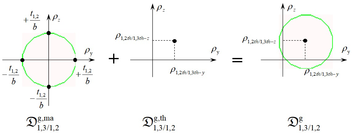
The geometric polytope characterising geometric variations between surfaces 1,3 and 1,2, brought about by manufacturing processes and cumulated with variations caused by thermo-mechanical strains, is then defined by the following Minkowski sum:

D 1,3/1,2 g = D 1,3/1,2 g,ma + D 1,3/1,2 g,th MathType@MTEF@5@5@+= feaagKart1ev2aaatCvAUfeBSjuyZL2yd9gzLbvyNv2CaerbuLwBLn hiov2DGi1BTfMBaeXatLxBI9gBaerbd9wDYLwzYbItLDharqqtubsr 4rNCHbGeaGqiVu0Je9sqqrpepC0xbbL8F4rqqrFfpeea0xe9Lq=Jc9 vqaqpepm0xbba9pwe9Q8fs0=yqaqpepae9pg0FirpepeKkFr0xfr=x fr=xb9adbaqaaeGaciGaaiaabaqaamaabaabaaGcbaWefv3ySLgzgj xyRrxDYbqeguuDJXwAKbIrYf2A0vNCaGqbaKqzGeGae83aWtucfa4a a0baaSqaaKqzadGaaGymaiaacYcacaaIZaGaai4laiaaigdacaGGSa GaaGOmaaWcbaqcLbmacaqGNbaaaKqzGeGaeyypa0Jae83aWtucfa4a a0baaSqaaKqzadGaaGymaiaacYcacaaIZaGaai4laiaaigdacaGGSa GaaGOmaaWcbaqcLbmacaqGNbGaaeilaiaab2gacaqGHbaaaKqzGeGa ey4kaSIae83aWtucfa4aa0baaSqaaKqzadGaaGymaiaacYcacaaIZa Gaai4laiaaigdacaGGSaGaaGOmaaWcbaqcLbmacaqGNbGaaeilaiaa bshacaqGObaaaaaa@69BD@ (26)

Determination of polytope D 1,3/1,2 g MathType@MTEF@5@5@+= feaagKart1ev2aaatCvAUfeBSjuyZL2yd9gzLbvyNv2CaerbuLwBLn hiov2DGi1BTfMBaeXatLxBI9gBaerbd9wDYLwzYbItLDharqqtubsr 4rNCHbGeaGqiVu0Je9sqqrpepC0xbbL8F4rqqrFfpeea0xe9Lq=Jc9 vqaqpepm0xbba9pwe9Q8fs0=yqaqpepae9pg0FirpepeKkFr0xfr=x fr=xb9adbaqaaeGaciGaaiaabaqaamaabaabaaGcbaWefv3ySLgzgj xyRrxDYbqeguuDJXwAKbIrYf2A0vNCaGqbaKqzGeGae83aWtucfa4a a0baaSqaaKqzadGaaGymaiaacYcacaaIZaGaai4laiaaigdacaGGSa GaaGOmaaWcbaqcLbmacaqGNbaaaaaa@4C0F@ is shown in Figure 13.

Figure 13 Characterisation of geometric deviations induced by manufacturing process and thermo-mechanical behaviour.

Integrating thermo-mechanical strains into the contacts

Simulation of a joint between two parts potentially in contact consists of determining the contact polytope in the event that the surfaces in contact are thermo-mechanically deformed. The condition of non-interference defined in (9) no longer depends only on clearance between the two surfaces due to manufacturing deviations but also on local clearance due to dimension and form deviations of thermo-mechanical origin. In this case, the non-interference constraints between surfaces i, j and u, v formalised in equation (27) generalise equation (9) where dN represents local clearance at point N:

N E c ε N,i,j/u,v . n N d N MathType@MTEF@5@5@+= feaagKart1ev2aaatCvAUfeBSjuyZL2yd9gzLbvyNv2CaerbuLwBLn hiov2DGi1BTfMBaeXatLxBI9gBaerbd9wDYLwzYbItLDharqqtubsr 4rNCHbGeaGqiVu0Je9sqqrpepC0xbbL8F4rqqrFfpeea0xe9Lq=Jc9 vqaqpepm0xbba9pwe9Q8fs0=yqaqpepae9pg0FirpepeKkFr0xfr=x fr=xb9adbaqaaeGaciGaaiaabeqaamaabaabaaGcbaqcLbsacqGHai IicaWGobGaeyicI4SaamyraKqbaoaaBaaaleaajugWaiaadogaaSqa baqcLbsacaaMf8UaaCyTdKqbaoaaBaaaleaaieaajugWaiaa=5eaca GGSaGaamyAaiaacYcacaWGQbGaai4laiaadwhacaGGSaGaamODaaWc beaajugibiaac6cacaWHUbqcfa4aaSbaaSqaaKqzadGaaeOtaaWcbe aajugibiabgsMiJkaadsgajuaGdaWgaaWcbaqcLbmacaqGobaaleqa aaaa@54FC@ (27)

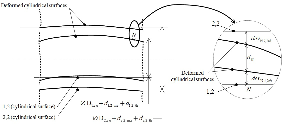
Local clearance dN at point N is defined as a function of clearance J between the two substituted surfaces and as a function of form deviations of thermo-mechanical origin de v N-i,jth MathType@MTEF@5@5@+= feaagKart1ev2aaatCvAUfeBSjuyZL2yd9gzLbvyNv2CaerbuLwBLn hiov2DGi1BTfMBaeXatLxBI9gBaerbd9wDYLwzYbItLDharqqtubsr 4rNCHbGeaGqiVu0Je9sqqrpepC0xbbL8F4rqqrFfpeea0xe9Lq=Jc9 vqaqpepm0xbba9pwe9Q8fs0=yqaqpepae9pg0FirpepeKkFr0xfr=x fr=xb9adbaqaaeGaciGaaiaabaqaamaabaabaaGcbaqcLbsacaWGKb GaamyzaiaadAhajuaGdaWgaaWcbaqcLbmacaqGobGaaeylaiaadMga caGGSaGaamOAaiabgkHiTiaadshacaWGObaaleqaaaaa@4226@ and de v N-u,vth MathType@MTEF@5@5@+= feaagKart1ev2aaatCvAUfeBSjuyZL2yd9gzLbvyNv2CaerbuLwBLn hiov2DGi1BTfMBaeXatLxBI9gBaerbd9wDYLwzYbItLDharqqtubsr 4rNCHbGeaGqiVu0Je9sqqrpepC0xbbL8F4rqqrFfpeea0xe9Lq=Jc9 vqaqpepm0xbba9pwe9Q8fs0=yqaqpepae9pg0FirpepeKkFr0xfr=x fr=xb9adbaqaaeGaciGaaiaabaqaamaabaabaaGcbaqcLbsacaWGKb GaamyzaiaadAhajuaGdaWgaaWcbaqcLbmacaqGobGaaeylaiaadwha caGGSaGaamODaiabgkHiTiaadshacaWGObaaleqaaaaa@423E@ in surfaces i, j and u, v respectively:

d N = J 2 +( de v N-i,jth de v N-u,vth ) MathType@MTEF@5@5@+= feaagKart1ev2aaatCvAUfeBSjuyZL2yd9gzLbvyNv2CaerbuLwBLn hiov2DGi1BTfMBaeXatLxBI9gBaerbd9wDYLwzYbItLDharqqtubsr 4rNCHbGeaGqiVu0Je9sqqrpepC0xbbL8F4rqqrFfpeea0xe9Lq=Jc9 vqaqpepm0xbba9pwe9Q8fs0=yqaqpepae9pg0FirpepeKkFr0xfr=x fr=xb9adbaqaaeGaciGaaiaabaqaamaabaabaaGcbaqcLbsacaWGKb qcfa4aaSbaaSqaaKqzadGaaeOtaaWcbeaajugibiabg2da9Kqbaoaa laaakeaajugibiaadQeaaOqaaKqzGeGaaGOmaaaacqGHRaWkjuaGda qadaGcbaqcLbsacaWGKbGaamyzaiaadAhajuaGdaWgaaWcbaqcLbma caqGobGaaeylaiaadMgacaGGSaGaamOAaiabgkHiTiaadshacaWGOb aaleqaaKqzGeGaeyOeI0IaamizaiaadwgacaWG2bqcfa4aaSbaaSqa aKqzadGaaeOtaiaab2cacaWG1bGaaiilaiaadAhacqGHsislcaWG0b GaamiAaaWcbeaaaOGaayjkaiaawMcaaaaa@5B95@ (28)

Figure 14 shows the case of the CP joint between surfaces 1,2 and 2,2 studied in paragraph 2.1.2 under thermo-mechanical behaviour. Here, clearance J between the two substituted surfaces is defined by the following equation:

J= D 2,2 D 1,2 =( D 2,2n + d 2,2_ma + d 2,2_th )( D 1,2n + d 1,2_ma + d 1,2_th ) with: D 1,2n , D 2,2n : nominal diameters d 1,2_ma , d 2,2_ma :diameter deviation du to manufacturing process d 1,2_th , d 2,2_th :diameter deviation du to thermomechanical strains MathType@MTEF@5@5@+= feaagKart1ev2aaatCvAUfeBSjuyZL2yd9gzLbvyNv2CaerbuLwBLn hiov2DGi1BTfMBaeXatLxBI9gBaerbd9wDYLwzYbItLDharqqtubsr 4rNCHbGeaGqiVu0Je9sqqrpepC0xbbL8F4rqqrFfpeea0xe9Lq=Jc9 vqaqpepm0xbba9pwe9Q8fs0=yqaqpepae9pg0FirpepeKkFr0xfr=x fr=xb9adbaqaaeGaciGaaiaabaqaamaabaabaaGceaqabeaajugibi aadQeacqGH9aqpciGGebqcfa4aaSbaaSqaaKqzadGaaGOmaiaacYca caGGYaaaleqaaKqzGeGaeyOeI0IaciiraKqbaoaaBaaaleaajugWai aaigdacaGGSaGaaiOmaaWcbeaajugibiabg2da9Kqbaoaabmaakeaa jugibiGacseajuaGdaWgaaWcbaqcLbmacaaIYaGaaiilaiaackdaca WGUbaaleqaamrr1ngBPrMrYf2A0vNCaeHbfv3ySLgzGyKCHTgD1jha iuaajugibiab=TcaRiaadsgajuaGdaWgaaWcbaqcLbmacaqGYaGaae ilaiaabkdacaqGFbGaaeyBaiaabggaaSqabaqcLbsacqWFRaWkcaWG Kbqcfa4aaSbaaSqaaKqzadGaaeOmaiaabYcacaqGYaGaae4xaiaabs hacaqGObaaleqaaaGccaGLOaGaayzkaaqcLbsacqGHsisljuaGdaqa daGcbaqcLbsaciGGebqcfa4aaSbaaSqaaKqzadGaaGymaiaacYcaca GGYaGaamOBaaWcbeaajugibiab=TcaRiaadsgajuaGdaWgaaWcbaqc LbmacaqGXaGaaeilaiaabkdacaqGFbGaaeyBaiaabggaaSqabaqcLb sacqWFRaWkcaWGKbqcfa4aaSbaaSqaaKqzadGaaeymaiaabYcacaqG YaGaae4xaiaabshacaqGObaaleqaaaGccaGLOaGaayzkaaaabaqcLb sacaqG3bGaaeyAaiaabshacaqGObGaaeOoaaGcbaqcLbsaciGGebqc fa4aaSbaaSqaaKqzadGaaGymaiaacYcacaGGYaGaamOBaaWcbeaaju gibiaacYcaciGGebqcfa4aaSbaaSqaaKqzadGaaGOmaiaacYcacaGG YaGaamOBaaWcbeaajugibiaacQdacaqGGaGaaeOBaiaab+gacaqGTb GaaeyAaiaab6gacaqGHbGaaeiBaiaabccacaqGKbGaaeyAaiaabgga caqGTbGaaeyzaiaabshacaqGLbGaaeOCaiaabohaaOqaaKqzGeGaam izaKqbaoaaBaaaleaajugWaiaabgdacaqGSaGaaeOmaiaab+facaqG TbGaaeyyaaWcbeaajugibiaacYcacaWGKbqcfa4aaSbaaSqaaKqzad GaaeOmaiaabYcacaqGYaGaae4xaiaab2gacaqGHbaaleqaaKqzGeGa aiOoaiaaysW7caqGKbGaaeyAaiaabggacaqGTbGaaeyzaiaabshaca qGLbGaaeOCaiaabccacaqGKbGaaeyzaiaabAhacaqGPbGaaeyyaiaa bshacaqGPbGaae4Baiaab6gacaqGGaGaaeizaiaabwhacaqGGaGaae iDaiaab+gacaqGGaGaaeyBaiaabggacaqGUbGaaeyDaiaabAgacaqG HbGaae4yaiaabshacaqG1bGaaeOCaiaabMgacaqGUbGaae4zaiaabc cacaqGWbGaaeOCaiaab+gacaqGJbGaaeyzaiaabohacaqGZbaakeaa jugibiaadsgajuaGdaWgaaWcbaqcLbmacaqGXaGaaeilaiaabkdaca qGFbGaaeiDaiaabIgaaSqabaqcLbsacaGGSaGaamizaKqbaoaaBaaa leaajugWaiaabkdacaqGSaGaaeOmaiaab+facaqG0bGaaeiAaaWcbe aajugibiaacQdacaaMe8UaaeizaiaabMgacaqGHbGaaeyBaiaabwga caqG0bGaaeyzaiaabkhacaqGGaGaaeizaiaabwgacaqG2bGaaeyAai aabggacaqG0bGaaeyAaiaab+gacaqGUbGaaeiiaiaabsgacaqG1bGa aeiiaiaabshacaqGVbGaaeiiaiaabshacaqGObGaaeyzaiaabkhaca qGTbGaae4Baiaab2gacaqGLbGaae4yaiaabIgacaqGHbGaaeOBaiaa bMgacaqGJbGaaeyyaiaabYgacaqGGaGaae4CaiaabshacaqGYbGaae yyaiaabMgacaqGUbGaae4Caaaaaa@2897@ (29)

Figure 14 Geometric deviations between two disturbed surfaces potentially in contact.

The least favourable configuration for assembly in terms of manufacturing deviations is that which corresponds to:

J min =( D 2,2n + ( d 2,2_ma ) mini + d 2,2_th )( D 1,2n + ( d 1,2_ma ) maxi + d 1,2_th ) MathType@MTEF@5@5@+= feaagKart1ev2aaatCvAUfeBSjuyZL2yd9gzLbvyNv2CaerbuLwBLn hiov2DGi1BTfMBaeXatLxBI9gBaerbd9wDYLwzYbItLDharqqtubsr 4rNCHbGeaGqiVu0Je9sqqrpepC0xbbL8F4rqqrFfpeea0xe9Lq=Jc9 vqaqpepm0xbba9pwe9Q8fs0=yqaqpepae9pg0FirpepeKkFr0xfr=x fr=xb9adbaqaaeGaciGaaiaabaqaamaabaabaaGcbaqcLbsacaWGkb qcfa4aaSbaaSqaaKqzadGaciyBaiaacMgacaGGUbaaleqaaKqzGeGa eyypa0tcfa4aaeWaaOqaaKqzGeGaciiraKqbaoaaBaaaleaajugWai aaikdacaGGSaGaaiOmaiaad6gaaSqabaWefv3ySLgzgjxyRrxDYbqe guuDJXwAKbIrYf2A0vNCaGqbaKqzGeGae83kaSscfa4aaeWaaOqaaK qzGeGaamizaKqbaoaaBaaaleaajugWaiaabkdacaqGSaGaaeOmaiaa b+facaqGTbGaaeyyaaWcbeaaaOGaayjkaiaawMcaaKqbaoaaBaaale aajugWaiaab2gacaqGPbGaaeOBaiaabMgaaSqabaqcLbsacqWFRaWk caWGKbqcfa4aaSbaaSqaaKqzadGaaeOmaiaabYcacaqGYaGaae4xai aabshacaqGObaaleqaaaGccaGLOaGaayzkaaqcLbsacqGHsisljuaG daqadaGcbaqcLbsaciGGebqcfa4aaSbaaSqaaKqzadGaaGymaiaacY cacaGGYaGaamOBaaWcbeaajugibiab=TcaRKqbaoaabmaakeaajugi biaadsgajuaGdaWgaaWcbaqcLbmacaqGXaGaaeilaiaabkdacaqGFb GaaeyBaiaabggaaSqabaaakiaawIcacaGLPaaajuaGdaWgaaWcbaqc LbmacaqGTbGaaeyyaiaabIhacaqGPbaaleqaaKqzGeGae83kaSIaam izaKqbaoaaBaaaleaajugWaiaabgdacaqGSaGaaeOmaiaab+facaqG 0bGaaeiAaaWcbeaaaOGaayjkaiaawMcaaaaa@903D@ (30)

Finally, equations are written as follows for the CP joint:

N E c { J 2 ( de v N-2,2th de v N-1,2th )( ε N1,2/2,2 +AN× ρ 1,2/2,2 ). n N J 2 +( de v N-2,2th de v N-1,2th ) } MathType@MTEF@5@5@+= feaagKart1ev2aqatCvAUfeBSjuyZL2yd9gzLbvyNv2CaerbuLwBLn hiov2DGi1BTfMBaeXatLxBI9gBaerbd9wDYLwzYbItLDharqqtubsr 4rNCHbGeaGqiVu0Je9sqqrpepC0xbbL8F4rqqrFfpeea0xe9Lq=Jc9 vqaqpepm0xbba9pwe9Q8fs0=yqaqpepae9pg0FirpepeKkFr0xfr=x fr=xb9adbaqaaeGaciGaaiaabeqaamaabaabaaGceaqabeaajugibi abgcGiIiaad6eacqGHiiIZcaWGfbqcfa4aaSbaaSqaaKqzadGaam4y aaWcbeaaaOqaaKqbaoaacmaakeaajugibiabgkHiTKqbaoaalaaake aajugibiaadQeaaOqaaKqzGeGaaGOmaaaacqGHsisljuaGdaqadaGc baqcLbsacaWGKbGaamyzaiaadAhajuaGdaWgaaWcbaqcLbmacaqGob GaaeylaiaaikdacaGGSaGaaGOmaiabgkHiTiaadshacaWGObaaleqa aKqzGeGaeyOeI0IaamizaiaadwgacaWG2bqcfa4aaSbaaSqaaKqzad GaaeOtaiaab2cacaqGXaGaaeilaiaabkdacqGHsislcaWG0bGaamiA aaWcbeaaaOGaayjkaiaawMcaaKqzGeGaeyizImAcfa4aaeWaaOqaaK qzGeGaaCyTdKqbaoaaBaaaleaajugWaiaad6eacqGHsislcaaIXaGa aiilaiaaikdacaGGVaGaaGOmaiaacYcacaaIYaaaleqaaKqzGeGaey 4kaSIaamyqaiaad6eacqGHxdaTcaWHbpqcfa4aaSbaaSqaaKqzadGa aGymaiaacYcacaaIYaGaai4laiaaikdacaGGSaGaaGOmaaWcbeaaaO GaayjkaiaawMcaaKqzGeGaaiOlaiaah6gajuaGdaWgaaWcbaqcLbma caWGobaaleqaaKqzGeGaeyizImAcfa4aaSaaaOqaaKqzGeGaamOsaa GcbaqcLbsacaaIYaaaaiabgUcaRKqbaoaabmaakeaajugibiaadsga caWGLbGaamODaKqbaoaaBaaaleaajugWaiaab6eacaqGTaGaaGOmai aacYcacaaIYaGaeyOeI0IaamiDaiaadIgaaSqabaqcLbsacqGHsisl caWGKbGaamyzaiaadAhajuaGdaWgaaWcbaqcLbmacaqGobGaaeylai aabgdacaqGSaGaaeOmaiabgkHiTiaadshacaWGObaaleqaaaGccaGL OaGaayzkaaaacaGL7bGaayzFaaaaaaa@A306@ (31)

The upper and lower boundaries of the halfspaces are no longer constants as they were in equation (9). It is not possible to express this polytope simply, in a similar way to (11). The polytope characterised by (31) is generally written D 1,2/2,2 c,th MathType@MTEF@5@5@+= feaagKart1ev2aaatCvAUfeBSjuyZL2yd9gzLbvyNv2CaerbuLwBLn hiov2DGi1BTfMBaeXatLxBI9gBaerbd9wDYLwzYbItLDharqqtubsr 4rNCHbGeaGqiVu0Je9sqqrpepC0xbbL8F4rqqrFfpeea0xe9Lq=Jc9 vqaqpepm0xbba9pwe9Q8fs0=yqaqpepae9pg0FirpepeKkFr0xfr=x fr=xb9adbaqaaeGaciGaaiaabaqaamaabaabaaGcbaWefv3ySLgzgj xyRrxDYbqeguuDJXwAKbIrYf2A0vNCaGqbaKqzGeGae83aWtucfa4a a0baaSqaaKqzadGaaGymaiaacYcacaaIYaGaai4laiaaikdacaGGSa GaaGOmaaWcbaqcLbmacaqGJbGaaeilaiaabshacaqGObaaaaaa@4E9C@ or D 1,2/2,2 c,th,min MathType@MTEF@5@5@+= feaagKart1ev2aaatCvAUfeBSjuyZL2yd9gzLbvyNv2CaerbuLwBLn hiov2DGi1BTfMBaeXatLxBI9gBaerbd9wDYLwzYbItLDharqqtubsr 4rNCHbGeaGqiVu0Je9sqqrpepC0xbbL8F4rqqrFfpeea0xe9Lq=Jc9 vqaqpepm0xbba9pwe9Q8fs0=yqaqpepae9pg0FirpepeKkFr0xfr=x fr=xb9adbaqaaeGaciGaaiaabaqaamaabaabaaGcbaWefv3ySLgzgj xyRrxDYbqeguuDJXwAKbIrYf2A0vNCaGqbaKqzGeGae83aWtucfa4a a0baaSqaaKqzadGaaGymaiaacYcacaaIYaGaai4laiaaikdacaGGSa GaaGOmaaWcbaqcLbmacaqGJbGaaeilaiaabshacaqGObGaaeilaiaa b2gacaqGPbGaaeOBaaaaaaa@5218@ giving consideration to (30). There are two possibilities:

  1. The intersection between the halfspaces defined by (25) generates a polytope,
  2. The intersection between the halfspaces defined by (26) generates an empty set.

Case (a) is illustrated in Figure 15 where the polytope D 1,2/2,2 c,th,min MathType@MTEF@5@5@+= feaagKart1ev2aaatCvAUfeBSjuyZL2yd9gzLbvyNv2CaerbuLwBLn hiov2DGi1BTfMBaeXatLxBI9gBaerbd9wDYLwzYbItLDharqqtubsr 4rNCHbGeaGqiVu0Je9sqqrpepC0xbbL8F4rqqrFfpeea0xe9Lq=Jc9 vqaqpepm0xbba9pwe9Q8fs0=yqaqpepae9pg0FirpepeKkFr0xfr=x fr=xb9adbaqaaeGaciGaaiaabaqaamaabaabaaGcbaWefv3ySLgzgj xyRrxDYbqeguuDJXwAKbIrYf2A0vNCaGqbaKqzGeGae83aWtucfa4a a0baaSqaaKqzadGaaGymaiaacYcacaaIYaGaai4laiaaikdacaGGSa GaaGOmaaWcbaqcLbmacaqGJbGaaeilaiaabshacaqGObGaaeilaiaa b2gacaqGPbGaaeOBaaaaaaa@5218@ , represented in two specific projection planes, characterises the relative positions of surfaces 1,2 and 2,2 at point A. Contact between 1,2 and 2,2 gives rise to no additional strain in the mechanical system. It is specified that the joint has floating contact.
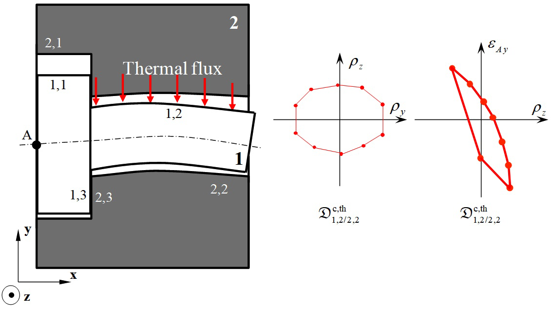
Figure 15 Contact polytope between two disturbed surfaces: case of no clamping.

Case (b) corresponds to a local clamping phenomenon, also called local tightening, between the two parts. No movement between the two surfaces relative to one another is possible: it is specified that the joint has fixed contact. The contact polytope D i,j/u,v c,th,min MathType@MTEF@5@5@+= feaagKart1ev2aaatCvAUfeBSjuyZL2yd9gzLbvyNv2CaerbuLwBLn hiov2DGi1BTfMBaeXatLxBI9gBaerbd9wDYLwzYbItLDharqqtubsr 4rNCHbGeaGqiVu0Je9sqqrpepC0xbbL8F4rqqrFfpeea0xe9Lq=Jc9 vqaqpepm0xbba9pwe9Q8fs0=yqaqpepae9pg0FirpepeKkFr0xfr=x fr=xb9adbaqaaeGaciGaaiaabaqaamaabaabaaGcbaWefv3ySLgzgj xyRrxDYbqeguuDJXwAKbIrYf2A0vNCaGqbaKqzGeGae83aWtucfa4a a0baaSqaaKqzadGaamyAaiaacYcacaWGQbGaai4laiaadwhacaGGSa GaamODaaWcbaqcLbmacaqGJbGaaeilaiaabshacaqGObGaaeilaiaa b2gacaqGPbGaaeOBaaaaaaa@52FB@ is a vertex that coincides with the origin: see Figure 16. Clamping will cause additional strains locally in the two parts in contact which will have to be determined in a thermo-mechanical simulation of the complete system.
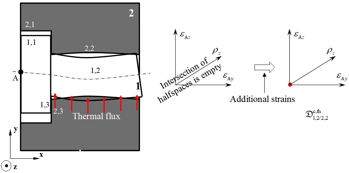
Figure 16 Contact polytope between two disturbed surfaces: case of clamping.

Condition for cycle closure

In paragraph 2.2, we saw that the topological structure of a mechanism is made up of a number of independent cycles and it must be ensured that these are closed. Closing a cycle requires the inclusion of D i,j/i,k g MathType@MTEF@5@5@+= feaagKart1ev2aaatCvAUfeBSjuyZL2yd9gzLbvyNv2CaerbuLwBLn hiov2DGi1BTfMBaeXatLxBI9gBaerbd9wDYLwzYbItLDharqqtubsr 4rNCHbGeaGqiVu0Je9sqqrpepC0xbbL8F4rqqrFfpeea0xe9Lq=Jc9 vqaqpepm0xbba9pwe9Q8fs0=yqaqpepae9pg0FirpepeKkFr0xfr=x fr=xb9adbaqaaeGaciGaaiaabaqaamaabaabaaGcbaqcfa4aaabqaO qaamrr1ngBPrMrYf2A0vNCaeHbfv3ySLgzGyKCHTgD1jhaiuaajugi biab=na8eLqbaoaaDaaaleaajugWaiaadMgacaGGSaGaamOAaiaac+ cacaWGPbGaaiilaiaadUgaaSqaaKqzadGaae4zaaaaaSqabeqajugi biabggHiLdaaaa@5009@ , the Minkowski sum of the geometric polytopes of the cycle, in D i,j/u,v c MathType@MTEF@5@5@+= feaagKart1ev2aaatCvAUfeBSjuyZL2yd9gzLbvyNv2CaerbuLwBLn hiov2DGi1BTfMBaeXatLxBI9gBaerbd9wDYLwzYbItLDharqqtubsr 4rNCHbGeaGqiVu0Je9sqqrpepC0xbbL8F4rqqrFfpeea0xe9Lq=Jc9 vqaqpepm0xbba9pwe9Q8fs0=yqaqpepae9pg0FirpepeKkFr0xfr=x fr=xb9adbaqaaeGaciGaaiaabaqaamaabaabaaGcbaqcfa4aaabqaO qaamrr1ngBPrMrYf2A0vNCaeHbfv3ySLgzGyKCHTgD1jhaiuaajugi biab=na8eLqbaoaaDaaaleaajugWaiaadMgacaGGSaGaamOAaiaac+ cacaWG1bGaaiilaiaadAhaaSqaaKqzadGaae4yaaaaaSqabeqajugi biabggHiLdaaaa@501C@ , the Minkowski sum of the contact polytopes of the cycle:

( D i,j/i,k g ) D i,j/u,v c MathType@MTEF@5@5@+= feaagKart1ev2aaatCvAUfeBSjuyZL2yd9gzLbvyNv2CaerbuLwBLn hiov2DGi1BTfMBaeXatLxBI9gBaerbd9wDYLwzYbItLDharqqtubsr 4rNCHbGeaGqiVu0Je9sqqrpepC0xbbL8F4rqqrFfpeea0xe9Lq=Jc9 vqaqpepm0xbba9pwe9Q8fs0=yqaqpepae9pg0FirpepeKkFr0xfr=x fr=xb9adbaqaaeGaciGaaiaabaqaamaabaabaaGcbaqcfa4aaeWaaO qaaKqbaoaaqaeakeaatuuDJXwAKzKCHTgD1jharyqr1ngBPrgigjxy RrxDYbacfaqcLbsacqWFdaprjuaGdaqhaaWcbaqcLbmacaWGPbGaai ilaiaadQgacaGGVaGaamyAaiaacYcacaWGRbaaleaajugWaiaabEga aaaaleqabeqcLbsacqGHris5aaGccaGLOaGaayzkaaqcLbsacqGHgk sZjuaGdaaeabGcbaqcLbsacqWFdaprjuaGdaqhaaWcbaqcLbmacaWG PbGaaiilaiaadQgacaGGVaGaamyDaiaacYcacaWG2baaleaajugWai aabogaaaaaleqabeqcLbsacqGHris5aaaa@642A@ (32)

In thermo-mechanical behaviour, equation (32) becomes:

( D i,j/i,k g,ma + D i,j/i,k g,th ) D i,j/u,v c,th MathType@MTEF@5@5@+= feaagKart1ev2aaatCvAUfeBSjuyZL2yd9gzLbvyNv2CaerbuLwBLn hiov2DGi1BTfMBaeXatLxBI9gBaerbd9wDYLwzYbItLDharqqtubsr 4rNCHbGeaGqiVu0Je9sqqrpepC0xbbL8F4rqqrFfpeea0xe9Lq=Jc9 vqaqpepm0xbba9pwe9Q8fs0=yqaqpepae9pg0FirpepeKkFr0xfr=x fr=xb9adbaqaaeGaciGaaiaabaqaamaabaabaaGcbaqcfa4aaabqaO qaaKqbaoaabmaakeaatuuDJXwAKzKCHTgD1jharyqr1ngBPrgigjxy RrxDYbacfaqcLbsacqWFdaprjuaGdaqhaaWcbaqcLbmacaWGPbGaai ilaiaadQgacaGGVaGaamyAaiaacYcacaWGRbaaleaajugWaiaabEga caqGSaGaaeyBaiaabggaaaqcLbsacqGHRaWkcqWFdaprjuaGdaqhaa WcbaqcLbmacaWGPbGaaiilaiaadQgacaGGVaGaamyAaiaacYcacaWG RbaaleaajugWaiaabEgacaqGSaGaaeiDaiaabIgaaaaakiaawIcaca GLPaaaaSqabeqajugibiabggHiLdGaeyOHI0Ccfa4aaabqaOqaaKqz GeGae83aWtucfa4aa0baaSqaaKqzadGaamyAaiaacYcacaWGQbGaai 4laiaadwhacaGGSaGaamODaaWcbaqcLbmacaqGJbGaaeilaiaabsha caqGObaaaaWcbeqabKqzGeGaeyyeIuoaaaa@7847@ (33)

with:

  1. D i,j/i,k g,ma MathType@MTEF@5@5@+= feaagKart1ev2aaatCvAUfeBSjuyZL2yd9gzLbvyNv2CaerbuLwBLn hiov2DGi1BTfMBaeXatLxBI9gBaerbd9wDYLwzYbItLDharqqtubsr 4rNCHbGeaGqiVu0Je9sqqrpepC0xbbL8F4rqqrFfpeea0xe9Lq=Jc9 vqaqpepm0xbba9pwe9Q8fs0=yqaqpepae9pg0FirpepeKkFr0xfr=x fr=xb9adbaqaaeGaciGaaiaabaqaamaabaabaaGcbaWefv3ySLgzgj xyRrxDYbqeguuDJXwAKbIrYf2A0vNCaGqbaKqzGeGae83aWtucfa4a a0baaSqaaKqzadGaamyAaiaacYcacaWGQbGaai4laiaadMgacaGGSa Gaam4AaaWcbaqcLbmacaqGNbGaaeilaiaab2gacaqGHbaaaaaa@4F5E@ + D i,j/i,k g,th MathType@MTEF@5@5@+= feaagKart1ev2aaatCvAUfeBSjuyZL2yd9gzLbvyNv2CaerbuLwBLn hiov2DGi1BTfMBaeXatLxBI9gBaerbd9wDYLwzYbItLDharqqtubsr 4rNCHbGeaGqiVu0Je9sqqrpepC0xbbL8F4rqqrFfpeea0xe9Lq=Jc9 vqaqpepm0xbba9pwe9Q8fs0=yqaqpepae9pg0FirpepeKkFr0xfr=x fr=xb9adbaqaaeGaciGaaiaabaqaamaabaabaaGcbaWefv3ySLgzgj xyRrxDYbqeguuDJXwAKbIrYf2A0vNCaGqbaKqzGeGae83aWtucfa4a a0baaSqaaKqzadGaamyAaiaacYcacaWGQbGaai4laiaadMgacaGGSa Gaam4AaaWcbaqcLbmacaqGNbGaaeilaiaabshacaqGObaaaaaa@4F6C@ : geometric polytope defining geometric variations between surfaces i, j and i, k of part i caused by manufacturing processes, cumulated with variations caused by thermo-mechanical strains in i in the free state,
  2. D i,j/u,v c,th MathType@MTEF@5@5@+= feaagKart1ev2aaatCvAUfeBSjuyZL2yd9gzLbvyNv2CaerbuLwBLn hiov2DGi1BTfMBaeXatLxBI9gBaerbd9wDYLwzYbItLDharqqtubsr 4rNCHbGeaGqiVu0Je9sqqrpepC0xbbL8F4rqqrFfpeea0xe9Lq=Jc9 vqaqpepm0xbba9pwe9Q8fs0=yqaqpepae9pg0FirpepeKkFr0xfr=x fr=xb9adbaqaaeGaciGaaiaabaqaamaabaabaaGcbaWefv3ySLgzgj xyRrxDYbqeguuDJXwAKbIrYf2A0vNCaGqbaKqzGeGae83aWtucfa4a a0baaSqaaKqzadGaamyAaiaacYcacaWGQbGaai4laiaadwhacaGGSa GaamODaaWcbaqcLbmacaqGJbGaaeilaiaabshacaqGObaaaaaa@4F7F@ : contact polytope which takes into account thermo-mechanical strains between surfaces i, j and u, v which are potentially in contact.

Determining polytope ( D i,j/i,k g,ma + D i,j/i,k g,th ) MathType@MTEF@5@5@+= feaagKart1ev2aaatCvAUfeBSjuyZL2yd9gzLbvyNv2CaerbuLwBLn hiov2DGi1BTfMBaeXatLxBI9gBaerbd9wDYLwzYbItLDharqqtubsr 4rNCHbGeaGqiVu0Je9sqqrpepC0xbbL8F4rqqrFfpeea0xe9Lq=Jc9 vqaqpepm0xbba9pwe9Q8fs0=yqaqpepae9pg0FirpepeKkFr0xfr=x fr=xb9adbaqaaeGaciGaaiaabaqaamaabaabaaGcbaqcfa4aaeWaaO qaamrr1ngBPrMrYf2A0vNCaeHbfv3ySLgzGyKCHTgD1jhaiuaajugi biab=na8eLqbaoaaDaaaleaajugWaiaadMgacaGGSaGaamOAaiaac+ cacaWGPbGaaiilaiaadUgaaSqaaKqzadGaae4zaiaabYcacaqGTbGa aeyyaaaajugibiabgUcaRiab=na8eLqbaoaaDaaaleaajugWaiaadM gacaGGSaGaamOAaiaac+cacaWGPbGaaiilaiaadUgaaSqaaKqzadGa ae4zaiaabYcacaqG0bGaaeiAaaaaaOGaayjkaiaawMcaaaaa@6121@ is described in paragraph 3.2. Determining polytope D i,j/u,v c,th MathType@MTEF@5@5@+= feaagKart1ev2aaatCvAUfeBSjuyZL2yd9gzLbvyNv2CaerbuLwBLn hiov2DGi1BTfMBaeXatLxBI9gBaerbd9wDYLwzYbItLDharqqtubsr 4rNCHbGeaGqiVu0Je9sqqrpepC0xbbL8F4rqqrFfpeea0xe9Lq=Jc9 vqaqpepm0xbba9pwe9Q8fs0=yqaqpepae9pg0FirpepeKkFr0xfr=x fr=xb9adbaqaaeGaciGaaiaabaqaamaabaabaaGcbaWefv3ySLgzgj xyRrxDYbqeguuDJXwAKbIrYf2A0vNCaGqbaKqzGeGae83aWtucfa4a a0baaSqaaKqzadGaamyAaiaacYcacaWGQbGaai4laiaadwhacaGGSa GaamODaaWcbaqcLbmacaqGJbGaaeilaiaabshacaqGObaaaaaa@4F7F@ is described in paragraph 3.3.

Figure 17 shows the three possible cases representing verification that the sum of the geometric polytopes is included in the sum of the contact polytopes, based on the example described in paragraph 2 in the most unfavourable configuration for the assembly. Figure 17a illustrates the following configuration:

( D 2,2/2,3 g,ma + D 2,2/2,3 g,th )+( D 1,3/1,2 g,ma + D 1,3/1,2 g,th )( D 1,2/2,2 c,min,th + D 2,3/1,3 c,th ) MathType@MTEF@5@5@+= feaagKart1ev2aaatCvAUfeBSjuyZL2yd9gzLbvyNv2CaerbuLwBLn hiov2DGi1BTfMBaeXatLxBI9gBaerbd9wDYLwzYbItLDharqqtubsr 4rNCHbGeaGqiVu0Je9sqqrpepC0xbbL8F4rqqrFfpeea0xe9Lq=Jc9 vqaqpepm0xbba9pwe9Q8fs0=yqaqpepae9pg0FirpepeKkFr0xfr=x fr=xb9adbaqaaeGaciGaaiaabaqaamaabaabaaGcbaqcfa4aaeWaaO qaamrr1ngBPrMrYf2A0vNCaeHbfv3ySLgzGyKCHTgD1jhaiuaajugi biab=na8eLqbaoaaDaaaleaajugWaiaaikdacaGGSaGaaGOmaiaac+ cacaaIYaGaaiilaiaaiodaaSqaaKqzadGaae4zaiaabYcacaqGTbGa aeyyaaaajugibiab=TcaRiab=na8eLqbaoaaDaaaleaajugWaiaaik dacaGGSaGaaGOmaiaac+cacaaIYaGaaiilaiaaiodaaSqaaKqzadGa ae4zaiaabYcacaqG0bGaaeiAaaaaaOGaayjkaiaawMcaaKqzGeGaey 4kaSscfa4aaeWaaOqaaKqzGeGae83aWtucfa4aa0baaSqaaKqzadGa aGymaiaacYcacaaIZaGaai4laiaaigdacaGGSaGaaGOmaaWcbaqcLb macaqGNbGaaeilaiaab2gacaqGHbaaaKqzGeGae83kaSIae83aWtuc fa4aa0baaSqaaKqzadGaaGymaiaacYcacaaIZaGaai4laiaaigdaca GGSaGaaGOmaaWcbaqcLbmacaqGNbGaaeilaiaabshacaqGObaaaaGc caGLOaGaayzkaaqcLbsacqGHgksZjuaGdaqadaGcbaqcLbsacqWFda prjuaGdaqhaaWcbaqcLbmacaaIXaGaaiilaiaaikdacaGGVaGaaGOm aiaacYcacaaIYaaaleaajugWaiaabogacaqGSaGaaeyBaiaabMgaca qGUbGaaeilaiaabshacaqGObaaaKqzGeGaey4kaSIae83aWtucfa4a a0baaSqaaKqzadGaaGOmaiaacYcacaaIZaGaai4laiaaigdacaGGSa GaaG4maaWcbaqcLbmacaqGJbGaaeilaiaabshacaqGObaaaaGccaGL OaGaayzkaaaaaa@A4AA@ (34)

Figure 17 Inclusion of a sum of geometric polytopes inside a sum of contact polytopes taking into account the thermo-mechanical behaviour of the system.

This means that it is possible to assemble the system without any further strain in the parts. Thermo-mechanical strains in the parts in the Free State leave sufficient clearance in the joints to produce the assembly. Figure 17b illustrates the following configuration:

( ( D 2,2/2,3 g,ma + D 2,2/2,3 g,th )+( D 1,3/1,2 g,ma + D 1,3/1,2 g,th ) )( D 1,2/2,2 c,min,th + D 2,3/1,3 c,th )= MathType@MTEF@5@5@+= feaagKart1ev2aaatCvAUfeBSjuyZL2yd9gzLbvyNv2CaerbuLwBLn hiov2DGi1BTfMBaeXatLxBI9gBaerbd9wDYLwzYbItLDharqqtubsr 4rNCHbGeaGqiVu0Je9sqqrpepC0xbbL8F4rqqrFfpeea0xe9Lq=Jc9 vqaqpepm0xbba9pwe9Q8fs0=yqaqpepae9pg0FirpepeKkFr0xfr=x fr=xb9adbaqaaeGaciGaaiaabaqaamaabaabaaGcbaqcfa4aaeWaaO qaaKqbaoaabmaakeaatuuDJXwAKzKCHTgD1jharyqr1ngBPrgigjxy RrxDYbacfaqcLbsacqWFdaprjuaGdaqhaaWcbaqcLbmacaaIYaGaai ilaiaaikdacaGGVaGaaGOmaiaacYcacaaIZaaaleaajugWaiaabEga caqGSaGaaeyBaiaabggaaaqcLbsacqWFRaWkcqWFdaprjuaGdaqhaa WcbaqcLbmacaaIYaGaaiilaiaaikdacaGGVaGaaGOmaiaacYcacaaI ZaaaleaajugWaiaabEgacaqGSaGaaeiDaiaabIgaaaaakiaawIcaca GLPaaajugibiabgUcaRKqbaoaabmaakeaajugibiab=na8eLqbaoaa DaaaleaajugWaiaaigdacaGGSaGaaG4maiaac+cacaaIXaGaaiilai aaikdaaSqaaKqzadGaae4zaiaabYcacaqGTbGaaeyyaaaajugibiab =TcaRiab=na8eLqbaoaaDaaaleaajugWaiaaigdacaGGSaGaaG4mai aac+cacaaIXaGaaiilaiaaikdaaSqaaKqzadGaae4zaiaabYcacaqG 0bGaaeiAaaaaaOGaayjkaiaawMcaaaGaayjkaiaawMcaaKqzGeGaey ykICCcfa4aaeWaaOqaaKqzGeGae83aWtucfa4aa0baaSqaaKqzadGa aGymaiaacYcacaaIYaGaai4laiaaikdacaGGSaGaaGOmaaWcbaqcLb macaqGJbGaaeilaiaab2gacaqGPbGaaeOBaiaabYcacaqG0bGaaeiA aaaajugibiabgUcaRiab=na8eLqbaoaaDaaaleaajugWaiaaikdaca GGSaGaaG4maiaac+cacaaIXaGaaiilaiaaiodaaSqaaKqzadGaae4y aiaabYcacaqG0bGaaeiAaaaaaOGaayjkaiaawMcaaKqzGeGaeyypa0 JaeyybIymaaa@A976@ (35)

This means that it is not possible to assemble the system without adding further strain in the parts. Equation (35) represents clamping of the cycle. Thermo-mechanical deformations in the free state have suppressed clearance in the joints enabling the assembly to be produced. A finite element thermo-mechanical simulation of the complete system must be carried out, taking into account the contact conditions between the parts under thermo-mechanical behaviour. Figure 17c illustrates the following configuration:

{ ( D 2,2/2,3 g,ma + D 2,2/2,3 g,th )+( D 1,3/1,2 g,ma + D 1,3/1,2 g,th )( D 1,2/2,2 c,min,th + D 2,3/1,3 c,th ) ( ( D 2,2/2,3 g,ma + D 2,2/2,3 g,th )+( D 1,3/1,2 g,ma + D 1,3/1,2 g,th ) )( D 1,2/2,2 c,min,th + D 2,3/1,3 c,th ) } MathType@MTEF@5@5@+= feaagKart1ev2aaatCvAUfeBSjuyZL2yd9gzLbvyNv2CaerbuLwBLn hiov2DGi1BTfMBaeXatLxBI9gBaerbd9wDYLwzYbItLDharqqtubsr 4rNCHbGeaGqiVu0Je9sqqrpepC0xbbL8F4rqqrFfpeea0xe9Lq=Jc9 vqaqpepm0xbba9pwe9Q8fs0=yqaqpepae9pg0FirpepeKkFr0xfr=x fr=xb9adbaqaaeGaciGaaiaabaqaamaabaabaaGcbaqcfa4aaiWaaO qaaKqzGeqbaeaabiqaaaGcbaqcfa4aaeWaaOqaamrr1ngBPrMrYf2A 0vNCaeHbfv3ySLgzGyKCHTgD1jhaiuaajugibiab=na8eLqbaoaaDa aaleaajugWaiaaikdacaGGSaGaaGOmaiaac+cacaaIYaGaaiilaiaa iodaaSqaaKqzadGaae4zaiaabYcacaqGTbGaaeyyaaaajugibiab=T caRiab=na8eLqbaoaaDaaaleaajugWaiaaikdacaGGSaGaaGOmaiaa c+cacaaIYaGaaiilaiaaiodaaSqaaKqzadGaae4zaiaabYcacaqG0b GaaeiAaaaaaOGaayjkaiaawMcaaKqzGeGaey4kaSscfa4aaeWaaOqa aKqzGeGae83aWtucfa4aa0baaSqaaKqzadGaaGymaiaacYcacaaIZa Gaai4laiaaigdacaGGSaGaaGOmaaWcbaqcLbmacaqGNbGaaeilaiaa b2gacaqGHbaaaKqzGeGae83kaSIae83aWtucfa4aa0baaSqaaKqzad GaaGymaiaacYcacaaIZaGaai4laiaaigdacaGGSaGaaGOmaaWcbaqc LbmacaqGNbGaaeilaiaabshacaqGObaaaaGccaGLOaGaayzkaaqcLb sacqGHekYYjuaGdaqadaGcbaqcLbsacqWFdaprjuaGdaqhaaWcbaqc LbmacaaIXaGaaiilaiaaikdacaGGVaGaaGOmaiaacYcacaaIYaaale aajugWaiaabogacaqGSaGaaeyBaiaabMgacaqGUbGaaeilaiaabsha caqGObaaaKqzGeGaey4kaSIae83aWtucfa4aa0baaSqaaKqzadGaaG OmaiaacYcacaaIZaGaai4laiaaigdacaGGSaGaaG4maaWcbaqcLbma caqGJbGaaeilaiaabshacaqGObaaaaGccaGLOaGaayzkaaqcLbsaca aMe8oakeaajuaGdaqadaGcbaqcfa4aaeWaaOqaaKqzGeGae83aWtuc fa4aa0baaSqaaKqzadGaaGOmaiaacYcacaaIYaGaai4laiaaikdaca GGSaGaaG4maaWcbaqcLbmacaqGNbGaaeilaiaab2gacaqGHbaaaKqz GeGae83kaSIae83aWtucfa4aa0baaSqaaKqzadGaaGOmaiaacYcaca aIYaGaai4laiaaikdacaGGSaGaaG4maaWcbaqcLbmacaqGNbGaaeil aiaabshacaqGObaaaaGccaGLOaGaayzkaaqcLbsacqGHRaWkjuaGda qadaGcbaqcLbsacqWFdaprjuaGdaqhaaWcbaqcLbmacaaIXaGaaiil aiaaiodacaGGVaGaaGymaiaacYcacaaIYaaaleaajugWaiaabEgaca qGSaGaaeyBaiaabggaaaqcLbsacqWFRaWkcqWFdaprjuaGdaqhaaWc baqcLbmacaaIXaGaaiilaiaaiodacaGGVaGaaGymaiaacYcacaaIYa aaleaajugWaiaabEgacaqGSaGaaeiDaiaabIgaaaaakiaawIcacaGL PaaaaiaawIcacaGLPaaajugibiabgMIihNqbaoaabmaakeaajugibi ab=na8eLqbaoaaDaaaleaajugWaiaaigdacaGGSaGaaGOmaiaac+ca caaIYaGaaiilaiaaikdaaSqaaKqzadGaae4yaiaabYcacaqGTbGaae yAaiaab6gacaqGSaGaaeiDaiaabIgaaaqcLbsacqGHRaWkcqWFdapr juaGdaqhaaWcbaqcLbmacaaIYaGaaiilaiaaiodacaGGVaGaaGymai aacYcacaaIZaaaleaajugWaiaabogacaqGSaGaaeiDaiaabIgaaaaa kiaawIcacaGLPaaajugibiabgcMi5kabgwGigdaaaOGaay5Eaiaaw2 haaaaa@13C5@ (36)

The inclusion condition is generally not verified. However, with certain configurations it is possible for the two parts to be assembled without further strain: the intersection of the two polytopes is not empty. This represents an uncertain clamping of the cycle.

Simulating respect of a functional requirement

Let us consider the functional condition defined by equation (17) characterised by the functional polytope D 1,1/2,1 f MathType@MTEF@5@5@+= feaagKart1ev2aaatCvAUfeBSjuyZL2yd9gzLbvyNv2CaerbuLwBLn hiov2DGi1BTfMBaeXatLxBI9gBaerbd9wDYLwzYbItLDharqqtubsr 4rNCHbGeaGqiVu0Je9sqqrpepC0xbbL8F4rqqrFfpeea0xe9Lq=Jc9 vqaqpepm0xbba9pwe9Q8fs0=yqaqpepae9pg0FirpepeKkFr0xfr=x fr=xb9adbaqaaeGaciGaaiaabaqaamaabaabaaGcbaWefv3ySLgzgj xyRrxDYbqeguuDJXwAKbIrYf2A0vNCaGqbaKqzGeGae83aWtucfa4a a0baaSqaaKqzadGaaGymaiaacYcacaaIXaGaai4laiaaikdacaGGSa GaaGymaaWcbaqcLbmacaqGMbaaaaaa@4C0C@ . Equation (20), which defines respect of the functional condition, remains the same, given that the topological structure of the system between the reference behaviour and thermo-mechanical behaviour remains the same by virtue of the hypotheses set out at the beginning of paragraph 3.1. In the first configuration, we assume that no local clamping is detected in the CP joint between 1,2 and 2,2 (see Figure 15) and that no clamping is detected in the cycle (see Figure 17a).

According to equation (22), it follows that:

D 1,1/2,1 g = D 1,1/1,3-1,2 g,ma + D 1,1/1,3-1,2 g,th +( D 1,2/2,2 c,th,max D 1,3/2,3 c,th )+ D 2,32,2/2,1 g,ma + D 2,32,2/2,1 g,th MathType@MTEF@5@5@+= feaagKart1ev2aaatCvAUfeBSjuyZL2yd9gzLbvyNv2CaerbuLwBLn hiov2DGi1BTfMBaeXatLxBI9gBaerbd9wDYLwzYbItLDharqqtubsr 4rNCHbGeaGqiVu0Je9sqqrpepC0xbbL8F4rqqrFfpeea0xe9Lq=Jc9 vqaqpepm0xbba9pwe9Q8fs0=yqaqpepae9pg0FirpepeKkFr0xfr=x fr=xb9adbaqaaeGaciGaaiaabaqaamaabaabaaGcbaWefv3ySLgzgj xyRrxDYbqeguuDJXwAKbIrYf2A0vNCaGqbaiab=na8enaaDaaaleaa caaIXaGaaiilaiaaigdacaGGVaGaaGOmaiaacYcacaaIXaaabaGaae 4zaaaakiabg2da9iab=na8enaaDaaaleaacaaIXaGaaiilaiaaigda caGGVaGaaeymaiaabYcacaqGZaGaaeylaiaabgdacaqGSaGaaeOmaa qaaiaabEgacaqGSaGaaeyBaiaabggaaaGccqWFRaWkcqWFdaprdaqh aaWcbaGaaGymaiaacYcacaaIXaGaai4laiaabgdacaqGSaGaae4mai aab2cacaqGXaGaaeilaiaabkdaaeaacaqGNbGaaeilaiaabshacaqG ObaaaOGae83kaSYaaeWaaeaacqWFdaprdaqhaaWcbaGaaGymaiaacY cacaaIYaGaai4laiaabkdacaqGSaGaaeOmaaqaaiaabogacaqGSaGa aeiDaiaabIgacaqGSaGaaeyBaiaabggacaqG4baaaOGaeyykICSae8 3aWt0aa0baaSqaaiaaigdacaGGSaGaaG4maiaac+cacaqGYaGaaeil aiaabodaaeaacaqGJbGaaeilaiaabshacaqGObaaaaGccaGLOaGaay zkaaGae83kaSIae83aWt0aa0baaSqaaiaaikdacaGGSaGaaG4maiab gkHiTiaaikdacaGGSaGaaGOmaiaac+cacaqGYaGaaeilaiaabgdaae aacaqGNbGaaeilaiaab2gacaqGHbaaaOGaey4kaSIae83aWt0aa0ba aSqaaiaaikdacaGGSaGaaG4maiabgkHiTiaaikdacaGGSaGaaGOmai aac+cacaqGYaGaaeilaiaabgdaaeaacaqGNbGaaeilaiaabshacaqG Obaaaaaa@9D85@ (37)

with:

  1. D 1,1/1,3-1,2 g,th MathType@MTEF@5@5@+= feaagKart1ev2aaatCvAUfeBSjuyZL2yd9gzLbvyNv2CaerbuLwBLn hiov2DGi1BTfMBaeXatLxBI9gBaerbd9wDYLwzYbItLDharqqtubsr 4rNCHbGeaGqiVu0Je9sqqrpepC0xbbL8F4rqqrFfpeea0xe9Lq=Jc9 vqaqpepm0xbba9pwe9Q8fs0=yqaqpepae9pg0FirpepeKkFr0xfr=x fr=xb9adbaqaaeGaciGaaiaabaqaamaabaabaaGcbaWefv3ySLgzgj xyRrxDYbqeguuDJXwAKbIrYf2A0vNCaGqbaKqzGeGae83aWtucfa4a a0baaSqaaKqzadGaaGymaiaacYcacaaIXaGaai4laiaabgdacaqGSa Gaae4maiaab2cacaqGXaGaaeilaiaabkdaaSqaaKqzadGaae4zaiaa bYcacaqG0bGaaeiAaaaaaaa@5158@ and D 2,32,2/2,1 g,th MathType@MTEF@5@5@+= feaagKart1ev2aaatCvAUfeBSjuyZL2yd9gzLbvyNv2CaerbuLwBLn hiov2DGi1BTfMBaeXatLxBI9gBaerbd9wDYLwzYbItLDharqqtubsr 4rNCHbGeaGqiVu0Je9sqqrpepC0xbbL8F4rqqrFfpeea0xe9Lq=Jc9 vqaqpepm0xbba9pwe9Q8fs0=yqaqpepae9pg0FirpepeKkFr0xfr=x fr=xb9adbaqaaeGaciGaaiaabaqaamaabaabaaGcbaWefv3ySLgzgj xyRrxDYbqeguuDJXwAKbIrYf2A0vNCaGqbaKqzGeGae83aWtucfa4a a0baaSqaaKqzadGaaGOmaiaacYcacaaIZaGaeyOeI0IaaGOmaiaacY cacaaIYaGaai4laiaabkdacaqGSaGaaeymaaWcbaqcLbmacaqGNbGa aeilaiaabshacaqGObaaaaaa@51A7@ : geometric polytopes representing deviations of thermo-mechanical origin in the free state in parts 1 and 2 respectively,
  2. D 1,1/1,3-1,2 g,ma MathType@MTEF@5@5@+= feaagKart1ev2aaatCvAUfeBSjuyZL2yd9gzLbvyNv2CaerbuLwBLn hiov2DGi1BTfMBaeXatLxBI9gBaerbd9wDYLwzYbItLDharqqtubsr 4rNCHbGeaGqiVu0Je9sqqrpepC0xbbL8F4rqqrFfpeea0xe9Lq=Jc9 vqaqpepm0xbba9pwe9Q8fs0=yqaqpepae9pg0FirpepeKkFr0xfr=x fr=xb9adbaqaaeGaciGaaiaabaqaamaabaabaaGcbaWefv3ySLgzgj xyRrxDYbqeguuDJXwAKbIrYf2A0vNCaGqbaKqzGeGae83aWtucfa4a a0baaSqaaKqzadGaaGymaiaacYcacaaIXaGaai4laiaabgdacaqGSa Gaae4maiaab2cacaqGXaGaaeilaiaabkdaaSqaaKqzadGaae4zaiaa bYcacaqGTbGaaeyyaaaaaaa@514A@ and D 2,32,2/2,1 g,ma MathType@MTEF@5@5@+= feaagKart1ev2aaatCvAUfeBSjuyZL2yd9gzLbvyNv2CaerbuLwBLn hiov2DGi1BTfMBaeXatLxBI9gBaerbd9wDYLwzYbItLDharqqtubsr 4rNCHbGeaGqiVu0Je9sqqrpepC0xbbL8F4rqqrFfpeea0xe9Lq=Jc9 vqaqpepm0xbba9pwe9Q8fs0=yqaqpepae9pg0FirpepeKkFr0xfr=x fr=xb9adbaqaaeGaciGaaiaabaqaamaabaabaaGcbaWefv3ySLgzgj xyRrxDYbqeguuDJXwAKbIrYf2A0vNCaGqbaKqzGeGae83aWtucfa4a a0baaSqaaKqzadGaaGOmaiaacYcacaaIZaGaeyOeI0IaaGOmaiaacY cacaaIYaGaai4laiaabkdacaqGSaGaaeymaaWcbaqcLbmacaqGNbGa aeilaiaab2gacaqGHbaaaaaa@5199@ : geometric polytope representing manufacturing deviations in parts 1 and 2 respectively,
  3. D 1,2/2,2 c,th,max MathType@MTEF@5@5@+= feaagKart1ev2aaatCvAUfeBSjuyZL2yd9gzLbvyNv2CaerbuLwBLn hiov2DGi1BTfMBaeXatLxBI9gBaerbd9wDYLwzYbItLDharqqtubsr 4rNCHbGeaGqiVu0Je9sqqrpepC0xbbL8F4rqqrFfpeea0xe9Lq=Jc9 vqaqpepm0xbba9pwe9Q8fs0=yqaqpepae9pg0FirpepeKkFr0xfr=x fr=xb9adbaqaaeGaciGaaiaabaqaamaabaabaaGcbaWefv3ySLgzgj xyRrxDYbqeguuDJXwAKbIrYf2A0vNCaGqbaKqzGeGae83aWtucfa4a a0baaSqaaKqzadGaaGymaiaacYcacaaIYaGaai4laiaaikdacaGGSa GaaGOmaaWcbaqcLbmacaGGJbGaaiilaiaacshacaGGObGaaiilaiGa c2gacaGGHbGaaiiEaaaaaaa@5224@ , D 1,3/2,3 c,th MathType@MTEF@5@5@+= feaagKart1ev2aaatCvAUfeBSjuyZL2yd9gzLbvyNv2CaerbuLwBLn hiov2DGi1BTfMBaeXatLxBI9gBaerbd9wDYLwzYbItLDharqqtubsr 4rNCHbGeaGqiVu0Je9sqqrpepC0xbbL8F4rqqrFfpeea0xe9Lq=Jc9 vqaqpepm0xbba9pwe9Q8fs0=yqaqpepae9pg0FirpepeKkFr0xfr=x fr=xb9adbaqaaeGaciGaaiaabaqaamaabaabaaGcbaWefv3ySLgzgj xyRrxDYbqeguuDJXwAKbIrYf2A0vNCaGqbaKqzGeGae83aWtucfa4a a0baaSqaaKqzadGaaGymaiaacYcacaaIZaGaai4laiaabkdacaqGSa Gaae4maaWcbaqcLbmacaqGJbGaaeilaiaabshacaqGObaaaaaa@4E8F@ : contact polytope incorporating thermo-mechanical strains between parts 1 and 2 of the CP joint with Jmax clearance and of the PP joint with null clearance respectively.

Respecting the functional condition FC in this first configuration is illustrated in Figure 18 and defined by(38):

t 1,1 2 t 2,1 2 J max th + ε A1,1th/1,3th1,2thy + ε A2,3th2,2th/2,1thy e min + t 1,1 2 + t 2,1 2 + J max th + ε A1,1th/1,3th1,2thy + ε A2,3th2,2th/2,1thy e max MathType@MTEF@5@5@+= feaagKart1ev2aaatCvAUfeBSjuyZL2yd9gzLbvyNv2CaerbuLwBLn hiov2DGi1BTfMBaeXatLxBI9gBaerbd9wDYLwzYbItLDharqqtubsr 4rNCHbGeaGqipv0Je9sqqrpepC0xbbL8F4rqqrFfpeea0xe9Lq=Jc9 vqaqpepm0xbba9pwe9Q8fs0=yqaqpepae9pg0FirpepeKkFr0xfr=x fr=xb9adbaqaaeGaciGaaiaabeqaamaabaabaaGceaqabeaajugibi abgkHiTSWaaSaaaOqaaKqzGeGaamiDaSWaa0baaeaajugibiaaigda caGGSaGaaGymaaWcbaaaaaGcbaqcLbsacaaIYaaaaiabgkHiTSWaaS aaaOqaaKqzGeGaamiDaSWaa0baaeaajugibiaaikdacaGGSaGaaGym aaWcbaaaaaGcbaqcLbsacaaIYaaaaiabgkHiTiaadQealmaaDaaaba qcLbmaciGGTbGaaiyyaiaacIhaaSqaaKqzadGaamiDaiaadIgaaaqc LbsacqGHRaWkcqaH1oqzlmaaBaaabaqcLbmacaWGbbGaeyOeI0IaaG ymaiaacYcacaaIXaGaamiDaiaadIgacaGGVaGaaGymaiaacYcacaaI ZaGaamiDaiaadIgacqGHsislcaaIXaGaaiilaiaaikdacaWG0bGaam iAaiabgkHiTiaadMhaaSqabaqcLbsacqGHRaWkcqaH1oqzlmaaBaaa baqcLbmacaWGbbGaeyOeI0IaaGOmaiaacYcacaaIZaGaamiDaiaadI gacqGHsislcaaIYaGaaiilaiaaikdacaWG0bGaamiAaiaac+cacaaI YaGaaiilaiaaigdacaWG0bGaamiAaiabgkHiTiaadMhaaSqabaqcLb sacqGHLjYSlmaavabakeqaleaajugWaiGac2gacaGGPbGaaiOBaaWc beGcbaqcLbsacaWGLbaaaaGcbaqcLbsacqGHRaWklmaalaaakeaaju gibiaadshalmaaDaaabaqcLbsacaaIXaGaaiilaiaaigdaaSqaaaaa aOqaaKqzGeGaaGOmaaaacqGHRaWklmaalaaakeaajugibiaadshalm aaDaaabaqcLbsacaaIYaGaaiilaiaaigdaaSqaaaaaaOqaaKqzGeGa aGOmaaaacqGHRaWkcaWGkbWcdaqhaaqaaKqzadGaciyBaiaacggaca GG4baaleaajugWaiaadshacaWGObaaaKqzGeGaey4kaSIaeqyTdu2c daWgaaqaaKqzadGaamyqaiabgkHiTiaaigdacaGGSaGaaGymaiaads hacaWGObGaai4laiaaigdacaGGSaGaaG4maiaadshacaWGObGaeyOe I0IaaGymaiaacYcacaaIYaGaamiDaiaadIgacqGHsislcaWG5baale qaaKqzGeGaey4kaSIaeqyTdu2cdaWgaaqaaKqzadGaamyqaiabgkHi TiaaikdacaGGSaGaaG4maiaadshacaWGObGaeyOeI0IaaGOmaiaacY cacaaIYaGaamiDaiaadIgacaGGVaGaaGOmaiaacYcacaaIXaGaamiD aiaadIgacqGHsislcaWG5baaleqaaKqzGeGaeyizIm6cdaqfqaGcbe WcbaqcLbmaciGGTbGaaiyyaiaacIhaaSqabOqaaKqzGeGaamyzaaaa aaaa@CC8B@ (38)

Figure 18 Respect of the Functional Condition FC by operations on polytopes: case of no clamping.

Let us consider the mechanism in a second configuration where local clamping in the CP joint between 1,2 and 2,2 (see Figure 16) and clamping of the cycle (see Figure 17b) have been detected. The appearance of one or several clamps requires a further thermo-mechanical study of the complete system to be carried out which takes into account these added strains over and above the strain on the parts in their free state. Clamping phenomena are modelled with marginal contact conditions between the parts in finite element modelling. When defining marginal contact conditions the characteristics of the joints defined in the thermo-mechanical behaviour must be respected:

  1. Cylindrical pair type contact of a fixed nature between 1,2 and 2,2,
  2. Planar pair type contact of a sliding nature (null clearance) between 1,3 and 2,3.

Figure 19 shows the result from a thermo-mechanical calculation on the complete system. The purpose of the thermo-mechanical simulation is to define the geometric polytope D 1,1/2,1 g,th MathType@MTEF@5@5@+= feaagKart1ev2aaatCvAUfeBSjuyZL2yd9gzLbvyNv2CaerbuLwBLn hiov2DGi1BTfMBaeXatLxBI9gBaerbd9wDYLwzYbItLDharqqtubsr 4rNCHbGeaGqiVu0Je9sqqrpepC0xbbL8F4rqqrFfpeea0xe9Lq=Jc9 vqaqpepm0xbba9pwe9Q8fs0=yqaqpepae9pg0FirpepeKkFr0xfr=x fr=xb9adbaqaaeGaciGaaiaabaqaamaabaabaaGcbaWefv3ySLgzgj xyRrxDYbqeguuDJXwAKbIrYf2A0vNCaGqbaKqzGeGae83aWtucfa4a a0baaSqaaKqzadGaaGymaiaacYcacaaIXaGaai4laiaaikdacaGGSa GaaGymaaWcbaqcLbmacaqGNbGaaeilaiaabshacaqGObaaaaaa@4E9E@ which will determine deviations of thermo-mechanical origin between surfaces 1,1 and 2,1. The method used is the same as in paragraph 3.2 to determine deviations of thermo-mechanical origin on a distorted part in the free state: see Figure 19.
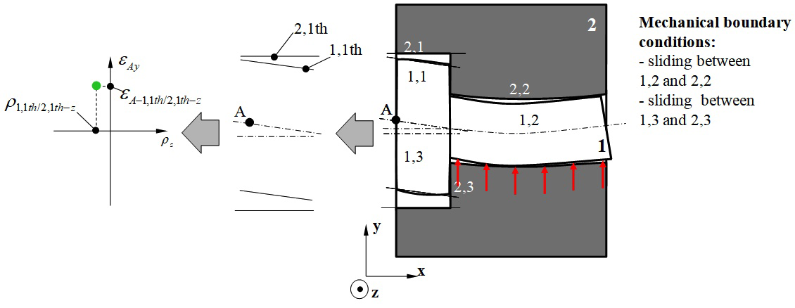
Figure 19 Characterisation of the thermo-mechanical behaviour of the complete system: case of clamping.

According to (21), this polytope is determined as follows:

D 1,1/2,1 g = D 1,1/2,1 g,th + D 1,1/1,3-1,2 g,ma +( D 1,2/2,2 c,th,max D 1,3/2,3 c,th )+ D 2,32,2/2,1 g,ma MathType@MTEF@5@5@+= feaagKart1ev2aaatCvAUfeBSjuyZL2yd9gzLbvyNv2CaerbuLwBLn hiov2DGi1BTfMBaeXatLxBI9gBaerbd9wDYLwzYbItLDharqqtubsr 4rNCHbGeaGqiVu0Je9sqqrpepC0xbbL8F4rqqrFfpeea0xe9Lq=Jc9 vqaqpepm0xbba9pwe9Q8fs0=yqaqpepae9pg0FirpepeKkFr0xfr=x fr=xb9adbaqaaeGaciGaaiaabaqaamaabaabaaGcbaWefv3ySLgzgj xyRrxDYbqeguuDJXwAKbIrYf2A0vNCaGqbaKqzGeGae83aWtucfa4a a0baaSqaaKqzadGaaGymaiaacYcacaaIXaGaai4laiaaikdacaGGSa GaaGymaaWcbaqcLbmacaqGNbaaaKqzGeGaeyypa0Jae83aWtucfa4a a0baaSqaaKqzadGaaGymaiaacYcacaaIXaGaai4laiaaikdacaGGSa GaaGymaaWcbaqcLbmacaqGNbGaaeilaiaabshacaqGObaaaKqzGeGa ey4kaSIae83aWtucfa4aa0baaSqaaKqzadGaaGymaiaacYcacaaIXa Gaai4laiaabgdacaqGSaGaae4maiaab2cacaqGXaGaaeilaiaabkda aSqaaKqzadGaae4zaiaabYcacaqGTbGaaeyyaaaajugibiab=TcaRK qbaoaabmaakeaajugibiab=na8eLqbaoaaDaaaleaajugWaiaaigda caGGSaGaaGOmaiaac+cacaqGYaGaaeilaiaabkdaaSqaaKqzadGaae 4yaiaabYcacaqG0bGaaeiAaiaabYcacaqGTbGaaeyyaiaabIhaaaqc LbsacqGHPiYXcqWFdaprjuaGdaqhaaWcbaqcLbmacaaIXaGaaiilai aaiodacaGGVaGaaeOmaiaabYcacaqGZaaaleaajugWaiaabogacaqG SaGaaeiDaiaabIgaaaaakiaawIcacaGLPaaajugibiab=TcaRiab=n a8eLqbaoaaDaaaleaajugWaiaaikdacaGGSaGaaG4maiabgkHiTiaa ikdacaGGSaGaaGOmaiaac+cacaqGYaGaaeilaiaabgdaaSqaaKqzad Gaae4zaiaabYcacaqGTbGaaeyyaaaaaaa@A290@ (39)

with:

  1. D 1,1/2,1 g,th MathType@MTEF@5@5@+= feaagKart1ev2aaatCvAUfeBSjuyZL2yd9gzLbvyNv2CaerbuLwBLn hiov2DGi1BTfMBaeXatLxBI9gBaerbd9wDYLwzYbItLDharqqtubsr 4rNCHbGeaGqiVu0Je9sqqrpepC0xbbL8F4rqqrFfpeea0xe9Lq=Jc9 vqaqpepm0xbba9pwe9Q8fs0=yqaqpepae9pg0FirpepeKkFr0xfr=x fr=xb9adbaqaaeGaciGaaiaabaqaamaabaabaaGcbaWefv3ySLgzgj xyRrxDYbqeguuDJXwAKbIrYf2A0vNCaGqbaKqzGeGae83aWtucfa4a a0baaSqaaKqzadGaaGymaiaacYcacaaIXaGaai4laiaaikdacaGGSa GaaGymaaWcbaqcLbmacaqGNbGaaeilaiaabshacaqGObaaaaaa@4E9E@ : geometric polytope characterising deviations of thermo-mechanical origin between surfaces 1,1 and 2,1 from the thermo-mechanical simulation of the complete system,
  2. D 1,1/1,3-1,2 g,ma MathType@MTEF@5@5@+= feaagKart1ev2aaatCvAUfeBSjuyZL2yd9gzLbvyNv2CaerbuLwBLn hiov2DGi1BTfMBaeXatLxBI9gBaerbd9wDYLwzYbItLDharqqtubsr 4rNCHbGeaGqiVu0Je9sqqrpepC0xbbL8F4rqqrFfpeea0xe9Lq=Jc9 vqaqpepm0xbba9pwe9Q8fs0=yqaqpepae9pg0FirpepeKkFr0xfr=x fr=xb9adbaqaaeGaciGaaiaabaqaamaabaabaaGcbaWefv3ySLgzgj xyRrxDYbqeguuDJXwAKbIrYf2A0vNCaGqbaKqzGeGae83aWtucfa4a a0baaSqaaKqzadGaaGymaiaacYcacaaIXaGaai4laiaabgdacaqGSa Gaae4maiaab2cacaqGXaGaaeilaiaabkdaaSqaaKqzadGaae4zaiaa bYcacaqGTbGaaeyyaaaaaaa@514A@ and D 2,32,2/2,1 g,ma MathType@MTEF@5@5@+= feaagKart1ev2aaatCvAUfeBSjuyZL2yd9gzLbvyNv2CaerbuLwBLn hiov2DGi1BTfMBaeXatLxBI9gBaerbd9wDYLwzYbItLDharqqtubsr 4rNCHbGeaGqiVu0Je9sqqrpepC0xbbL8F4rqqrFfpeea0xe9Lq=Jc9 vqaqpepm0xbba9pwe9Q8fs0=yqaqpepae9pg0FirpepeKkFr0xfr=x fr=xb9adbaqaaeGaciGaaiaabaqaamaabaabaaGcbaWefv3ySLgzgj xyRrxDYbqeguuDJXwAKbIrYf2A0vNCaGqbaKqzGeGae83aWtucfa4a a0baaSqaaKqzadGaaGOmaiaacYcacaaIZaGaeyOeI0IaaGOmaiaacY cacaaIYaGaai4laiaabkdacaqGSaGaaeymaaWcbaqcLbmacaqGNbGa aeilaiaab2gacaqGHbaaaaaa@5199@ : geometric polytope characterising manufacturing deviations in parts 1 and 2 respectively,
  3. D 1,2/2,2 c,th,max MathType@MTEF@5@5@+= feaagKart1ev2aaatCvAUfeBSjuyZL2yd9gzLbvyNv2CaerbuLwBLn hiov2DGi1BTfMBaeXatLxBI9gBaerbd9wDYLwzYbItLDharqqtubsr 4rNCHbGeaGqiVu0Je9sqqrpepC0xbbL8F4rqqrFfpeea0xe9Lq=Jc9 vqaqpepm0xbba9pwe9Q8fs0=yqaqpepae9pg0FirpepeKkFr0xfr=x fr=xb9adbaqaaeGaciGaaiaabaqaamaabaabaaGcbaWefv3ySLgzgj xyRrxDYbqeguuDJXwAKbIrYf2A0vNCaGqbaKqzGeGae83aWtucfa4a a0baaSqaaKqzadGaaGymaiaacYcacaaIYaGaai4laiaaikdacaGGSa GaaGOmaaWcbaqcLbmacaGGJbGaaiilaiaacshacaGGObGaaiilaiGa c2gacaGGHbGaaiiEaaaaaaa@5224@ , D 1,3/2,3 c,th MathType@MTEF@5@5@+= feaagKart1ev2aaatCvAUfeBSjuyZL2yd9gzLbvyNv2CaerbuLwBLn hiov2DGi1BTfMBaeXatLxBI9gBaerbd9wDYLwzYbItLDharqqtubsr 4rNCHbGeaGqiVu0Je9sqqrpepC0xbbL8F4rqqrFfpeea0xe9Lq=Jc9 vqaqpepm0xbba9pwe9Q8fs0=yqaqpepae9pg0FirpepeKkFr0xfr=x fr=xb9adbaqaaeGaciGaaiaabaqaamaabaabaaGcbaWefv3ySLgzgj xyRrxDYbqeguuDJXwAKbIrYf2A0vNCaGqbaKqzGeGae83aWtucfa4a a0baaSqaaKqzadGaaGymaiaacYcacaaIZaGaai4laiaabkdacaqGSa Gaae4maaWcbaqcLbmacaqGJbGaaeilaiaabshacaqGObaaaaaa@4E8F@ : contact polytope between parts 1 and 2 of the cylindrical pair joint with Jmax and the planar pair joint respectively including thermo-mechanical strains.

Respect of functional condition FC in this second configuration is illustrated in Figure 20 and defined by equation (40):

t 1,1 2 t 2,1 2 + ε A1,1th/2,1thy e min + t 1,1 2 + t 2,1 2 + ε A1,1th/2,1thy e max MathType@MTEF@5@5@+= feaagKart1ev2aaatCvAUfeBSjuyZL2yd9gzLbvyNv2CaerbuLwBLn hiov2DGi1BTfMBaeXatLxBI9gBaerbd9wDYLwzYbItLDharqqtubsr 4rNCHbGeaGqipv0Je9sqqrpepC0xbbL8F4rqqrFfpeea0xe9Lq=Jc9 vqaqpepm0xbba9pwe9Q8fs0=yqaqpepae9pg0FirpepeKkFr0xfr=x fr=xb9adbaqaaeGaciGaaiaabeqaamaabaabaaGceaqabeaajugibi abgkHiTSWaaSaaaOqaaKqzGeGaamiDaSWaa0baaeaajugibiaaigda caGGSaGaaGymaaWcbaaaaaGcbaqcLbsacaaIYaaaaiabgkHiTSWaaS aaaOqaaKqzGeGaamiDaSWaa0baaeaajugibiaaikdacaGGSaGaaGym aaWcbaaaaaGcbaqcLbsacaaIYaaaaiabgUcaRiabew7aLTWaaSbaae aajugWaiaadgeacqGHsislcaaIXaGaaiilaiaaigdacaWG0bGaamiA aiaac+cacaaIYaGaaiilaiaaigdacaWG0bGaamiAaiabgkHiTiaadM haaSqabaqcLbsacqGHLjYSlmaavabakeqaleaajugWaiGac2gacaGG PbGaaiOBaaWcbeGcbaqcLbsacaWGLbaaaaGcbaqcLbsacqGHRaWklm aalaaakeaajugibiaadshalmaaDaaabaqcLbsacaaIXaGaaiilaiaa igdaaSqaaaaaaOqaaKqzGeGaaGOmaaaacqGHRaWklmaalaaakeaaju gibiaadshalmaaDaaabaqcLbsacaaIYaGaaiilaiaaigdaaSqaaaaa aOqaaKqzGeGaaGOmaaaacqGHRaWkcqaH1oqzlmaaBaaabaqcLbmaca WGbbGaeyOeI0IaaGymaiaacYcacaaIXaGaamiDaiaadIgacaGGVaGa aGOmaiaacYcacaaIXaGaamiDaiaadIgacqGHsislcaWG5baaleqaaK qzGeGaeyizIm6cdaqfqaGcbeWcbaqcLbmaciGGTbGaaiyyaiaacIha aSqabOqaaKqzGeGaamyzaaaaaaaa@83A4@ (40)

Figure 20 Respect of the Functional Condition FC by operations on polytopes: case of clamping.

Proposal for a global tolerancing procedure

Global tolerance analysis procedure

The organisational chart in Figure 21 breaks down the procedure proposed in this article into two distinct parts. The first corresponds to the preparation of the reference tolerance analysis model representing the reference behaviour. The start data consists of:

  1. A functional requirement,
  2. CAD model of the complete system,
  3. Specifications for contact between the parts,
  4. ISO geometric specifications for the parts.
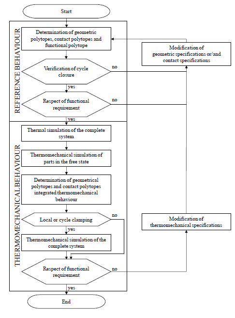
Figure 21 Global method of tolerancing analysis taking into account thermo-mechanical behaviour.

If the system cannot be assembled without distorting the parts (i.e. if cycle closure independent of the system graph is not possible) or if the functional requirement is not respected, then the global method has provisions for suggesting to the designer that the geometric specifications of the parts should be modified. This may simply involve reducing the dimensions of the tolerance zones and increasing minimum clearance, for example. If this is not sufficient, perhaps in terms of manufacturing criticality criteria, then it is suggested that the designer modifies the contact specifications. This may involve removing or adding joints and hence potentially modifying the number of parts. In general, this modifies the system architecture considerably. Implementation of the tolerance analysis process in this first part of the global method is described in paragraph 2. All thermo-mechanical behaviours are based on the reference model in accordance with the hypotheses set out in paragraph 3.

Next, the tolerance analysis model of specific thermo-mechanical behaviour is produced. The thermo-mechanical specifications of the system are added to the start data needed to produce the reference model. These are temperature and material specifications. In the first phase, temperature specifications are taken into account in a thermal simulation of the complete system. In the second phase, the thermo-mechanical strains of all the parts in the free state are determined. For these two phases we used a commercial thermo-mechanical finite element calculation tool. In the third phase, all the joints are characterised by a thermo-mechanical contact polytope incorporating the variations in dimension and form of surfaces potentially in contact. In this way, any possible local clamping (or tightening) between two parts can be detected. Finally, by simulating closure of the independent cycles any clamping of the cycles can be identified. If clamping is detected, a thermo-mechanical study of the complete system is carried out to determine the thermo-mechanical variations in the surfaces specified by the functional requirement in terms of situation, dimension and form deviations. If no clamping is detected, the thermo-mechanical behaviour of the system depends only on strains in the parts in the free state: no further thermo-mechanical simulation is required. Finally, if the functional requirement is not respected, then this suggests that the designer should modify the thermo-mechanical specifications as well as the geometric specifications of the parts and the contact specifications of the system. In general, modifying the temperature, materials or contact specifications can change the system architecture considerably. Implementation of the tolerance analysis processes in this second part of the global method is described in section 3.

Discussion of the proposed procedure

The operational cycle of the system studied is discretized into several behaviours: one reference behaviour and several thermo-mechanical behaviours. The reference behaviour is based on modelling infinitely rigid solids and does not take into account any strain that may be caused by residual stresses during manufacture or assembly. Each thermo-mechanical behaviour is defined by constant temperature specifications. The functioning of a high pressure turbine is thus defined by a finite set of behaviours where the turbine combustion chamber is at 20°C. This set of behaviours characterises the turboshaft engine's thermo-mechanical operating cycle.38 The thermo-mechanical behaviour of the system is assumed to be elastic. In addition, the invariance of the topological structure of contacts between behaviours means that geometrical variations in the system can be determined from closure of the same cycles in all behaviours. These cycles characterise the 3D dimension chains and determine the operations (Minkowski sum and intersection) to be put in place. These operations are characterised in the reference behaviour. Only the polytope operands are liable to change from one behaviour to another. The global method outlined in Figure 21 uses a finite element thermo-mechanical simulation tool.

This tolerance analysis method is based solely on a worst case analysis.

Conclusions and future developments

We have shown how to use operations on polytopes to characterise geometric variations limited by ISO geometric specifications for the parts and by contact specifications between the parts. After setting up a method adapted to modelling a system of infinitely rigid solids, we described the principles of integrating thermo-mechanical strain in the parts and the contacts. Statistical formulations are planned in future studies, but these may prove ineffective in behaviours where the original determinist thermo-mechanical deviations are very great in comparison with deviations due to manufacturing processes. Finally, future developments are planned which will take into account strains arising from residual stresses in manufacturing processes (e.g. Resin Transfer Moulding) or in assembly processes where rivets or bolts are used. This will enhance the multiphysical nature of this approach.

Acknowledgments

None.

Conflicts of interest

Authors declare that there is no conflict of interest.

References

  1. Fleming A. Geometric relationships between toleranced features. Artificial Intelligence. 1988;37(1-3):403‒412.
  2. Teissandier D, Couétard Y, Gérard A. A Computer Aided Tolerancing Model : Proportioned Assemblies Clearance Volume. Computer-Aided Design. 1999;31(13):805‒817.
  3. Requichaa AAG. Toward a theory of geometric tolerancing. The International Journal of Robotics Research. 1993;2(4):45‒60.
  4. Geometrical Product Specifications (GPS), Geometrical tolerancing, Tolerances of form, orientation, location and run-out. ISO. 1101:2004.
  5. Giordano M, Pairel E, Samper S. Mathematical representation of tolerance zones. In Netherlands: Proc. of 6th CIRP Seminar on Computer Aided Tolerancing Enschede; 1999. 177‒186 p.
  6. Roy U, Li B. Representation and interpretation of geometric tolerances for polyhedral objects. II.: Size, orientation and position tolerances. Computer-Aided Design. 1999;31(4):273‒285.
  7. Davidson JK, Mujezinovic A, Shah JJ. A new mathematical model for geometric tolerances as applied to round faces. ASME Transactions on Journal of Mechanical Design. 2002;124(4):609‒622.
  8. Fleming AD. Analysis of Uncertainties and Geometric Tolerances in Assemblies of Parts. PhD thesis, Scotland: University of Edinburgh; 1987.
  9. Srinivasan V. Role of Sweeps in Tolerancing Semantics. CRTD. 1993;27:69‒78.
  10. Wu Y, Shah JJ, Davidson JK. Improvements to algorithms for computing the Minkowski sum of 3-polytopes. Computer-Aided Design. 2003;35(13):1181‒1192.
  11. Teissandier D, Delos V. Algorithm to calculate the Minkowski sums of 3-polytopes based on normal fans. Computer-Aided Design. 2011;43(12):1567‒1576.
  12. Giordano M, Duret D. Clearance Space and Deviation Space. In: Proc. of 3rd CIRP seminar on Computer Aided Tolerancing, Cachan (France); 1993. 179‒196 p.
  13. Teissandier D, Delos V. Operations on polytopes: application to tolerance analysis. In: Proc. of 6th CIRP Seminar on Computer Aided Tolerancing, Enschede (Netherlands); 1999. 425‒433 p.
  14. Shah JJ, Ameta G, Shen Z, et al. Navigating the tolerance analysis maze. Computer-Aided Design and Applications. 2007;4(5):705‒718.
  15. Anselmetti B. Generation of functional tolerancing based on positioning features. Computer-Aided Design. 2006;38(8):902‒919.
  16. Clozel P, Rance PA. MECAmaster: a Tool for Assembly Simulation from Early Design, Industrial Approach. In: Geometric tolerancing of products. ISTE-WILEY; 2010. 241‒273 p.
  17. Ballot E, Bourdet P. Geometrical behavior laws for computer aided tolerancing. In: Proc. of 4th CIRP Seminar on Computer Aided Tolerancing, Tokyo (Japan); 1995. 143‒153 p.
  18. Johannesson H, Soderberg R. Structure and matrix models for tolerance analysis from configuration to detail design. Research in Engineering Design. 2000;12(2):112‒125.
  19. Tolerance Analysis, GD&T, and Quality Solutions. DCS; 2011.
  20. Bourdet P, Thiébaut F, Cid G. Writing the 3D Chain of Dimensions (Tolerance Stack-Up) in Symbolic Expressions. In: Geometric tolerancing of products. ISTE-WILEY; 2010. 125‒149 p.
  21. Stewart ML, Chase KW. Variation simulation of fixtured assembly for compliant structures using piecewise-linear analysis. Orlando (USA): Proc. of ASME IMECE2005-82371; 2005. 591‒600 p.
  22. Hu JS, Camelio J. Modeling and control compliant assembly systems. CIRP Annals. 2006;55(1):19‒22.
  23. Söderberg R, Lindkvist L, Dahlström S. Computer-aided robustness analysis for compliant assemblies. Journal of Engineering Design. 2006;17(5):411‒428.
  24. Maciej M, Leary M, Subic A. Computer Aided Tolerancing (CAT) platform for the design of assemblies under external and internal forces. Computer-Aided Design. 2011;43(6):707‒719.
  25. Samper S, Petit J, Giordano M. Elastic clearance domain and use rate concept applications to ball bearing and gears. In: Proc. of 9th CIRP Seminar on Computer Aided Tolerancing; 2005. 331–340 p.
  26. Bourdet P, Mathieu L, Lartigue C, et al. The concept of the small displacement torsor in metrology. Advanced Mathematical Tools in Metrology II. 1996;40:110‒122.
  27. Clément A, Bourdet P. A study of optimal-criteria identification based on the small-displacement screw model. CIRP Annals. 1988;37(1):503‒506.
  28. Boissonnat JD, Yvinec M, Algorithmic Geometry. Cambridge University Press; 1998.
  29. Ziegler G. Lectures on polytopes. Springer Verlag; 1995.
  30. Defazio TL, Edsall AC, Gustavson RE, et al. A prototype of feature based design for assembly. Journal of Mechanical Design. 1993;115(4):723‒734.
  31. Whitney DE, Adams JD. Application of screw theory to analysis of mobility and constraint of mechanisms. Journal of Mechanical Design. 2001;123:26‒32.
  32. Dantan JY, Mathieu L, Ballu A, et al. Tolerance synthesis: quantifier notion and virtual boundary. Computer-Aided Design. 2005;37(2):231‒240.
  33. Dufaure J, Teissandier D. A tolerancing framework to support geometric specifications traceability. International Journal of Advanced Manufacturing Technology. 2008;36(9-10):894‒907.
  34. Kinematic diagrams-Graphical symbols-Part 1. ISO; 1981.
  35. Ballu A, Mathieu L, Legoff O. Representation of Mechanical Assemblies and Specifications by Graphs. In: Geometric tolerancing of products. ISTE-WILEY; 2010. 87‒110 p.
  36. Giordano M, Samper S, Pairel E. Tolerance Analysis and Synthesis, Method of Domains. In: Geometric tolerancing of products. ISTE-Wiley; 2010. 152‒181 p.
  37. Pierre L, Teissandier D, Nadeau JP. Integration of thermomechanical strains into tolerancing analysis. International Journal on Interactive Design and Manufacturing. 2009;3:247‒263.
  38. Pierre L, Teissandier D, Nadeau JP. Integration of multiple physical behaviours into a geometric tolerancing approach. In: Proc. of 11th CIRP Seminar on Computer Aided Tolerancing in CDRom, Annecy (France); 2009. 9 p.
Creative Commons Attribution License

©2019 Teissandier, et al. This is an open access article distributed under the terms of the, which permits unrestricted use, distribution, and build upon your work non-commercially.