Condition on the state parameters
The equilibrium of a mechanical system is reached when the sum of the forces and moments are equal to zero. This leads to write that the acceleration of the body and the rate of change of angular momentum are null. Thus, considering a body with 6 Degree of Freedom (DoF) described by the 12 state parameters including:
- The velocity (3 coordinates);
- The angular rate (3 coordinates);
- The position (3 coordinates);
- The orientation or attitude (3 coordinates).
The equilibrium is reached when the time derivative of each parameter is equal to zero, except for the 3 position coordinates for which the second time derivative is equal to zero. Thus, the 12 state parameters have been divided into two complementary vectors:
- The first vector, noted
, gathers the 3 position coordinates;
- The second vector, noted
, gathers the 9 other state parameters.
With this notation, the equilibrium is defined by:
(1)
Case of a variable mass system
Let us assume that each coordinate xi of the vector
is described by a first order differential equation gi function of the state variables and mass of the system. In addition, each position coordinate yi of the vector
is described by a first order differential equation hi coming from the kinematics equations and function of the state variables only but not mass:
(2)
The equations gi and hi are gathered in the vectors
and
resp., which leads to write:
(3)
Considering that a variation of mass affects the equations gi only, a variation dm during dt leads to a variation
and dxi given by:
i.e.:
which can also be written in the matrix form:
with:
and:
The traditional equilibrium condition (EQ. (1)) gives in this case:
This expression means that the equilibrated condition
is generally not kept in time with a mass variation. Thus, another condition must be introduced to keep the equilibrium conditions (EQ. (1)) when the mass varies. This leads to the definition of an “extended trimmed conditions” given by:
(4)
Considering that
, the vectoris a constant noted
. Then, (EQ. (4)) can also be written as:
(5)
The theoretical framework of the definition of the extended equilibrium is now applied to the case of a pure longitudinal flight, i.e. a flight in the vertical plane only. In this case, the airplane has 3 DoF, i.e. 1 in rotation (pitch) and 2 in the vertical plane (horizontal and vertical movement), and 6 state variables describe the motion of the aircraft in this case.
Assumptions and models
In this application, the atmosphere state parameters are given by the International Standard Atmosphere (ISA) model.9 For analytical computations, an exponential model of air density is defined:10
(6)
where ρref and zref denote reference air density and altitude depending on the atmosphere layer.
In the troposphere, i.e. from sea level to 11km of altitude where the temperature decreases linearly, ah is approximated by a least-squares curve fit of the actual evolution of the air density vs. altitude, i.e.:
In the lower stratosphere, i.e. from 11 km to 25 km of altitude where the temperature is constant, ah is directly
computed with the ideal gas law, i.e.:
Drag and lift are the result of the projection of the aerodynamic force acting on the aircraft on the longitudinal
aerodynamic axes:11
(7)
In these expressions, V denotes the True Air Speed (TAS), S corresponds to the aircraft’s reference area and the coefficients CD and CL are the drag and lift coefficient resp. The drag coefficient CD is modeled as:15
(8)
where K corresponds the induced drag factor and CDo denotes the parasite drag coefficient.
Considering simple static models, the lift coefficient CL is a function of the angle of attack α only:
Concerning the aerodynamic pitching moment M, we have:
(9)
The pitching moment coefficient Cm is expressed in terms of angle of attack α, pitch rate q and elevator deflection δe:13
(10)
The thrust is assumed to be proportional to the air density and throttle lever δx:14
(11)
In this expression, TSL denotes the total thrust of the aircraft at sea level.
Longitudinal equations of motion
As said above, it’s necessary to take into account 6 state variables to describe the motion of a pure longitudinal flight. The first 2 state variables concern the position of the aircraft in the vertical plane, i.e. the horizontal distance x and altitude z.
Each variable is given by a first order differential equation coming from the kinematics:
(12)
where γ denotes the Flight Path Angle (FPA) of the aircraft.
With these equations, it is possible to define the vectors
and, i.e.:
Considering a symmetric aircraft with the thrust aligned with the fuselage reference line, the longitudinal equations of motion are the projections of the Newton’s second law on the aerodynamic axes:15
(13)
Assuming that the thrust is located at the aircraft center of gravity, the pitch rate comes from the aerodynamic pitching moment only16 and we have:
(14)
This set is completed by the kinematic equations in pitch:
(15)
With these equations, it’s possible to define the vectors
and
:
Definition of the extended trimmed conditions
The first condition coming from the definition of the extended equilibrium (EQ. (5)), i.e.
, leads to:
(16)
The second condition from (EQ. (5)), i.e.
, gives:
where C1 and C2 denote the 2 coordinates of
.
For the third condition from (EQ. (5)), it’s necessary to compute the matrix Gy:
i.e.:
With (EQ. (16)), this leads to:
We also have:
With (EQ. (16)), this leads to:
Finally, the third condition from (EQ. (5)) gives the following vector equation:
This leads to a single condition on the evolution of the altitude in trimmed condition when the mass varies:
(17)
Finally, the longitudinal trimmed condition of the aircraft taking into account the case
is defined as follows:
(18)
Discussion of the results
In extended trimmed conditions when the mass varies, the equations (EQ. (18)) show that the altitude must increase
when the mass decreases
to keep the equilibrium.
These equations also show that the condition on altitude
only apply to the case
, i.e. at constant mass. Moreover, as no equation in
depends on the horizontal distance x, i.e.
, it’s not possible to compute the constant C1 corresponding to
, and the only condition in this case is
.
In addition, as we also have
, this gives the following expression of
:
(19)
which means that the mass variationmust be proportional to the total mass m to get a trimmed condition in longitudinal flight. For an aircraft equipped with jet engines, this condition can be achieved through a very simple model with a fuel flow rate proportional to the thrust:
(20)
where cT denotes the thrust-specific fuel consumption (TSFC).
Indeed, considering the thrust given by the trimmed conditions, this leads to the following expression of the equilibrated thrust:
which gives:
Assuming that the TSFC cT remains constant and as every parameter in this equation are constant in trimmed condition, including α and γ which are small, this leads to:
(21)
Thus, this expression is equivalent to (EQ. (19)), which also gives the value of C2:
(22)
Analytical computation of the extended trimmed conditions
In this paragraph, the trimmed conditions in longitudinal flight at constant mass will be corrected to get the exact trimmed conditions when the mass varies.
To get this correction, the mass variation is assumed to be equivalent to the form given by (EQ. (19)), i.e.:
(23)
with
constant.
To clarify the notations, the subscript e denotes an equilibrated parameter computed with
, whereas the subscriptdenotes an equilibrated parameter computed with
.
In addition, the comparison between both cases will be performed at a given weight for the same case of altitude and True Airspeed, i.e.:
As
when the mass varies (EQ. (18)), by introducing both the kinematic equation in altitude (EQ. (12)) and the expression of m˙ (EQ. (23)), this leads to:
i.e.:
(24)
Moreover, the pitch rate is equal to zero in both cases, i.e.:
(25)
The longitudinal trimmed equations are written at constant weight (lift and drag equations):
(26)
and with varying mass:
(27)
Assuming that the equilibrated FPA
is very small and considering that
and
, this
leads to:
Assuming that αe and
are small, the difference between each drag equation gives:
which leads to:
(28)
where ɛδx denotes the relative correction on the throttle lever δx to consider the mass variation, i.e.:
Moreover, the difference between each lift equation gives:
which finally leads to:
(29)
where ɛα is the relative correction on α to consider the mass variation, i.e.:
Considering that the longitudinal trimmed condition is also given by the condition Cm = 0 in both cases, we have:
The difference between both equations gives:
which leads to:
(30)
where ɛδe denotes the relative correction on the elevator deflection δe to consider the mass variation, i.e.:
Numerical verification
These results have been verified through a numerical simulation performed in the case of a twin-engine aircraft representative of the Airbus wide-body family:17
- Total mass: m=130 103 kg
- Reference area: Sref=260m2
- Lift-slope derivative: CLα=5 rad−1
- Induced drag factor: K=0.055
- Parasite drag coefficient: CDo=0.02
- Pitch stiffness: Cmα=−1 rad−1
- Pitch control effectiveness: Cmδe=−1.46 rad−1
- Total thrust at sea level: TSL=470 103N
The aircraft is assumed to fly in cruise at ze=30 000 ft and M=0.82, i.e. Ve=248.58 m/s, with=−10−5 kg/s which corresponds to a typical fuel consumption during the cruising phase. From initial conditions computed at ze and Ve, the mass variation
has been applied abruptly, leading to the evolution of the longitudinal state vector computed with a numerical solver based on the Runge-Kutta algorithm.
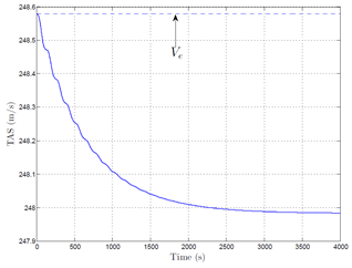
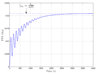
Firstly, the computation is initialized with the trimmed condition with, i.e. γ0 = 0, α0 = αe, q0 = 0, δe = δee, δx = δxe. The figures (Figure 1) and (EQ. (2)) show that, after a transient including a classical “phugoïd mode” and a slow aperiodic mode, the TAS reaches a final state slightly different from the initial value. Moreover, the figure (Figure 2) shows that the FPA reaches a stabilized value
equal to its analytical expression, i.e..

Figure 1 Evolution of the TAS vs. time with
initiated with the traditional equilibrium.

Figure 2 Evolution of the FPA vs. time with
initiated with the traditional equilibrium.
The second step is to compute the evolution of the system with the simulation initiated with the corrected trimmed conditions with
, i.e.
, q0=0,
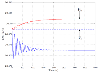
. The figure (Figure 3) shows that the TAS (red curve) is well stabilized in time and almost equal to Ve in these conditions (relative difference equal to 4 10−6). Concerning the FPA, the figure (Figure 4) shows the transient in this case is very small and
during the whole simulation.

Figure 3 Evolution of the TAS vs. time with
initiated with the extended equilibrium.

Figure 4 Evolution of the FPA vs. time with
initiated with the extended equilibrium.
This computation also shows that the correction ɛα and ɛδe can be considered as second order terms. Indeed, considering the simulation initiated with
, α0 = αe, q0 = 0, δe = δee,
, i.e. without correcting the terms αe and δee, the evolution of the system (blue curve) is very close to the complete correction. In this case, the main difference lies in the transient which is slightly more pronounced.
Finally, the comparison between the trimmed conditions computed at a given altitude and airspeed considering a constant mass, i.e., vs. the trimmed conditions taking into account a mass variation given by
, are gathered in the following tabular with the “first order” and “second order” corrections:
|
Correction
|
|
First order
|
Second order
|
|
Flight Path Angle
|
γe = 0
|
|
|
|
AoA
|
αe
|
|
|
|
Pitching rate
|
qe = 0
|
|
|
|
Elevator deflection
|
δee
|
|
|
|
Throttle position
|
δxe
|
|
|


