Research Article Volume 2 Issue 1
A theoretical checking for resistive instabilities into the plasma: one proposed criterion for identification of the plasma waves
Xaplanteris CL,1
Regret for the inconvenience: we are taking measures to prevent fraudulent form submissions by extractors and page crawlers. Please type the correct Captcha word to see email ID.

Xaplanteris SC2
1Plasma Physics Laboratory, NCSR ?Demokritos, Greece
2School of Civil Engineering, National Technical University of Athens, Greece
Correspondence: Constantine L Xaplanteris, Plasma Physics Laboratory, Institute of Nanoscience and Nanotechnology (I.N.N.), National Centre for Scientific Research, N.C.S.R. ?Demokritos?, 153 10, Athens, Greece, Tel 2106857429
Received: November 22, 2017 | Published: February 6, 2018
Citation: Xaplanteris CL, Xaplanteris SC. A theoretical checking for resistive instabilities into the plasma: one proposed criterion for identification of theplasma waves. Phys Astron Int J. 2018;2(1):74-79. DOI: 10.15406/paij.2018.02.00051
Download PDF
Abstract
As the resistive instabilities with their serious difficulty at the thermonuclear fusion programs have concentrated much interest of the researchers, the present study has the ambition to provide an applicable and useful criterion for examining and identifying if a observed plasma wave is resistive or not. A dispersion relation is obtained, by using the two fluids equation and considering that a resistive force exists, and then the growth rate can be solved. Subsequently, the resistance factor is calculated using the experimental values and data obtained. Finally, a comparison of the calculated resistance factor with the ones published in bibliography will be performed, which gives the expected answer about the type of the examined wave.
Keywords: Thermonuclear fusion; Fluids equation; Plasma physics; Astrophysics; Energy; Plasma waves; Electric field
Introduction
The resistive instabilities are between the most investigated phenomena of the plasma physics and the astrophysics, as well,1–5 and the dripping on these are passed-printed in the relevant bibliography.6–10 Early 60’s the topic has been investigated very enough as it is accused for energy losses in the plasma,11 but and presently the interest on them is very strong.12–14 As the all instabilities resulted into every kind plasma waves and their organized energy is absents from the plasmas' chaotic (thermal) energy, so, early they faced as obstacles in the thermonuclear fusion process.15–17 Instabilities in fusion plasmas appear at all times and by many types of them, therefore it will not try to catalog them here. Only instabilities and plasma waves which investigated and studied in our plasma laboratory of ‘Demokritos’ are mentioned in the present and this briefly. So, early 70's, ion-acoustic waves have been fund into non magnetized argon plasma,18 and after this the energy losses of the plasma due to these waves have been published as well.19 Furthermore, drift waves have been fund into magnetized argon plasma (in Q-machine), whish identified as caused on the if electric field gradient.20 With newer publications the influence of these drift waves on the Hall conductivity of the plasma have be given.21,22 Recently, another kind low frequency waves observed into our semi Q-machine; these waves identified as collisional one and caused on the electron-neutral collisions as well.23 As the experience with the plasma wave’s study have be increased, it was appears the need to finding a criterion suitable for the identification of the appeared waves into our plasma. With the present theoretical work a criterion is proposed, suitable to distinguish if a plasma wave is resistive or not.
As our experience on the plasma waves' study have be increase, it was appears the need to finding a criterion for the identification of the appeared waves into our plasma. By the present work a criterion is proposed, suitable to distinguish if a wave is resistive or not.
For this way, the kinetic equation for both, ions and electrons have be taken, with the inclusion of the resistance term, and after mathematical elaboration and the necessary approaches we resulted with the dispersion relation (D.R.),from which the growth rate have be calculated; so, the derived resistance’s factor may be the indicator for a resistive wave or not.
The paper is written as following: the apparatus's description and the experimental data are presented in Section 2. Afterwards, the D.R. is elaborated in the Section 3, and its complete study has been made in the next Section 4. Finally, in the Section 5 the Conclusion-discussion has been given. The paper is ended with the Appendix A and Appendix B, which contain more mathematical details for alleviation of the text.
The experimental part
Although many improvised experimental devices are produced and used in the plasma laboratory of 'Demokritos', only two of them are mentions here: the first was the device into which by a non-magnetized argon plasma, the ion-acoustic instabilities appeared, and decently the semi-Q machine where the drift waves caused on the rf electrical field gradient, and the collisional instabilities are appear and studied, as well.
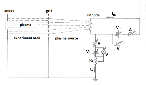
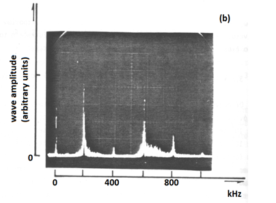
In the Figure 1 the first apparatus is shown, when in the Figure 2 (A) the spectrum of the ion-acoustic wave is presented and the Figure 2 (B) is a photo of oscillator screen.

Figure 1 The arrangement of the plasma production and the experiment’s space are presented.

Figure 2A The spectrum one typical ion-acoustic wave and its harmonic are presented.

Figure 2B ThreeA photo of the oscillator’s screen is given.
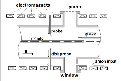
In the Figure 3 the drawing of the Q machine is shown and in the Figure 4 (A&B) the spectrum of the drifts waves and the collisional are given, as well.

Figure 3 A drawing of the ‘Demokritos’ Q-machine is shown.

Figure 4 (a) The spectrum one typical drift wave and (b) the spectrum one typical collisional wave have been given too.
Furthermore, on the Table 1 the typical values of the plasma parameters for the ion-acoustic wave are presented.
|
|
Minimum Value
|
Maximum Value
|
|
Argon pressure
|
|
|
|
Argon number density,
|
|
|
|
Anodic circuit power
|
|
|
|
Electron velocity
|
|
|
|
Electron density,
|
|
|
|
Electron temperature,
|
|
|
|
Ion temperature,
|
|
|
|
Electron-neutral collision frequency,
|
|
|
|
Ion-acoustic velocity,
|
|
|
|
Wave’s frequency,
|
|
|
Table 1 The plasma parameters ranging values in ion-acoustic waves
Likewise, on the Table 2 the analogous plasma parameters in the Q-machine are given.
|
|
Minimum value
|
Maximum value
|
|
Argon pressure
|
|
|
|
Argon number density,
|
|
|
|
Magnetic field intensity,
|
|
|
|
Microwaves' power, P
Frequency of the rf power (standard value)
|
|
|
|
Electron density,
|
|
|
|
Electron temperature,
|
|
|
|
Ion temperature,
|
|
|
|
Ionization rate
|
|
|
|
Electron drift velocity,
|
|
|
|
Electron-neutral collision frequency,
|
|
|
Table 2 The plasma parameters ranging values in Q-machine
The dispersion relation finding
The kinetic equation for the ions is written as following:
(1)
It is valid that
(Because the ions have low temperature
)
It is valid the Ampere’s law,
and the relation
Then, it is results the equation,
(2)
It is valid the relation
And the equation (2) is written as following;
(3)
The equation (1) due to equation (2) becomes,
(4)
By taking the following relations,
,
,
And separating in the two components, it is written as,
(5)
By putting the
from the last relation into equation (5) it is taken:
(6)
From the Ampere’s Law we have the equation (3)
For electrons, The continuity equation for electrons, keeping the first order terms only may be written as following,
Fitting the suitable tensor in the above continuity equation we have,
(7)
(Where is
)
The equation of motion for electrons is,
By using the equation (2), the last term of the above equation is formed as following,
And by putting it into the last equation it becomes,
Where it is valid
the thermal velocity.
From equation (7) we have
And the above equation becomes,
(8)
Now, the equation (8) is separated in two components from which the first equation becomes,
The above value of the
is enter into equation (3) and the value of the component
will be find, so
With the substitution of the into the eq.(6) we resulted with the complete dispersion relation,
(9)
The dispersion relation study
The fund dispersion relation may be written as following:
It is valid that
(the Debay length) and
, the ion-acoustic velocity then, we have,
(10)
By taking the approaches
and
,
The last relation may be written in the simple form,
The dispersion relation additional elaboration
Now, the equation (10) with mathematical elaboration (Appendix A) gives the following equation (11),
(11)
Which may becomes,
(12)
Order -arrangement according to forces
The last equation (12) may be written,
A separation of real and imaginaries parts is making in the next,
(13)
The growth rate calculation
By taking the approaches below,
,
,
,
And putting them into the last equation (13), we may be to define the real part and the imaginary part of its. So, we have the following.
Real Part
The real part is,
Imaginary Part
The imaginary part is as well,
Considering that the below approach
is valid, then the imaginary part is written,
By putting,
,
the last relation becomes,
Which by using suitable mathematical elaboration (Appendix B), we results with,
By using the approach
, and then,
. The last becomes,
or
If the last equation is solved for the factor, then is taken the following,
(14)
From which we may to calculate its value.
Conclusion & discussion
By inserting in the equation (14) the typical experimental values it is may to calculate the resistance factor and compare its value with the standard values which are given from the bibliography. So, the factor operates as criterion for the resistive waves; existence.
In the present instance there are the values,
,
,
,
,
Inserting into equation (14) it is resulted with the value,
In the next it is estimate the value by the Spitzer form -theory,
and is resulted with the value,
In addition, by using the formula
and is ended with
From the equation of motion for electrons is produced that,
as well.
Finally, if we use the Spitzer equation as it formed from the Wesson,
with
and,
it is taken out
.
By this comparison it is concluded that the examined waves is far away from to be considered and identified as resistive one.
Acknowledgments
The authors wish to thank all the previous and present members of the Plasma Laboratory of NCSR "Demokritos" for their assistance in the completion of the present study. Special thanks to Jenny and Christina for their offer to proofread the manuscript and their help with the editing of the paper and the use of the English language.
Conflicts of interest
Authors declare there is no conflict of interest.
References
- Roberts KV, Taylor JB. Gravitational Resistive Instability of an Incompressible plasma in a sheared Magnetic Field. The Physics of Fluids. 1965;8(2):315–322.
- Chen FF. ‘Universal’ Overstability of a Resistive Inhomogeneous Plasma. The Physics of Fluids. 1965;8(7):1323–1333.
- Saito S, Hatta Y. Measurements of Growth and Damping Rate of Resistive Instability in Gaseous Plasma. Journal of Physical Society of Japan. 1969;26(1):175–181.
- Shivamoggi KB. Resistive Instabilities in plasma. Astrophysics and Space Science. 1985;114(1):15–22.
- Litvak AA, Fisch JN. Resistive instabilities in Hall current plasma discharge. Physics of Plasmas. 2001;8(2):648–651.
- Spitzer L. Physics of Fully Ionised Gases. Interscience Publishers, New York, USA. 1962.
- Tanenbaun BS. Plasma physics. McGraw-Hill Education, USA. 1967.
- Krall N, Trivelpiece A. Principles of Plasma Physics. McGraw-Hill Kogakusha, Tokyo, Japan. 1973.
- Lieberman M, Lichtenberg A. Principles of Plasma Discharges and Materials Processing. Wiley and Sons, New York, USA. 1994.
- Wesson J. Tokamaks. 2nd edn, Clarendon Press-Oxford, UK. 1997.
- Coppi B, Greene J, Johnson J. Resistive Instabilities in a diffuse linear pinch. Nuclear Fusion. 1966;6(2):101–119.
- Shukla PK. Nonlinear waves and structures in dusty plasmas. Physics of Plasmas. 2003;10(5):1619–1627.
- Vranjes J, Pandey BP, Poedts S. Collisional instability of the drift wave in multi-component plasmas. Planetary and Space Science. 2006;54(7):695–700.
- Bashir MF, Vranjes J. Drift wave stabilized by an additional streaming ion or plasma population. Physical Review E. 2015;91(3):033–113.
- Melrose DB. Reactive and resistive nonlinear instabilities. Journal of Plasma Physics. 1986;36(2):269–279.
- Sharapov SE, Alper B, Berk HL, et al. Energetic particle instabilities in fusion plasma. Nuclear Fusion. 2013;53(10):104022–104033.
- Mazzucato E. Electromagnetic Waves for Thermonuclear Fusion Research. Princeton Plasma Physics Laboratory, USA. 2014.
- Anastassiades JA, Karatzas TN. Transfer of energy to light ions from the ion‐acoustic‐wave instability developed in a heavy‐ion plasma. Journal of Applied Physics. 1973;44(10).
- Anastassiades JA, Sideris E. Energy losses due to an ion-acoustic wave in a plasma. Journal of Applied Physics. 1980;51(11).
- Anastassiades JA, Xaplanteris LC. Drift Wave Instability in the Presence of an RF-Field in a Magnetized Plasma. Journal of Physical Society of Japan. 1983;52:492–500.
- Xaplanteris LC. Effects of Low-Frequency Instability on Hall Conductivity in Plasma: Applications to Astrophysics and Space Physics. Astrophysics and Space Science. 1987;136(1):171–181.
- Xaplanteris LC. Effects of Low-Frequency Instability on Hall Conductivity in Plasma. Astrophysics and Space Science. 1987;139(2):233–242.
- Xaplanteris LC. Collisional instability into a rare magnetized plasma. An experimental model for magnetospheric and space plasma study. Journal of Plasma Physics. 2009;75(3):395–406.

©2018 Xaplanteris, et al. This is an open access article distributed under the terms of the,
which
permits unrestricted use, distribution, and build upon your work non-commercially.


