MOJ
eISSN: 2577-8374


Mini Review Volume 2 Issue 2
University Academy of sciences, Republic of Uzbekistan Institute of Material sciences scientific production Association "Physics-sun", Uzbekistan
Correspondence: Yuldash Sobirov, University Academy of sciences Republic of Uzbekistan Institute of Material sciences scientific production Association "Physics-sun", Bodomzor yuli street 2B, Tashkent, Uzbekistan, Tel 998944081064
Received: July 26, 2018 | Published: August 14, 2018
Citation: Sobirov Y, Makhmudov S. Methods of measurement of high-concentrated solar energy flows. MOJ Solar Photoen Sys. 2018;2(2):62-64. DOI: 10.15406/mojsp.2018.02.00025
The paper often presents methods used to measure highly concentrated solar energy fluxes. A comparative analysis of the errors of each of them is made.
Keywords: concentrated flow, focal zone, radiometer, calorimeter, photometer
High-temperature solar installations, like the Big Solar Furnace (BSF) with a thermal power of 1,000kW in Uzbekistan and France, as well as other high-precision paraboloid concentrators, allow receiving concentrated flows with a density of 1000 W/cm2 in the focal zone.1,2 As we know, measuring a powerful stationary stream of concentrated solar energy up to 700 ÷ 1000W/cm2 is quite a challenge (Figure 1).
Devices should measure the energy flow regardless of the spectral composition of the radiation. Various instruments are used to measure such flows: cavity radiometers, calorimeters, photometers and heat flux sensors of various designs.3
The cavity radiometer uses the principle of comparing fluxes from a measured object and a calibrated standard cavity imitating an absolutely black body. Errors in the application of this method, except errors associated with the accuracy of measuring instruments, are determined by the degree of blackness of the measured object, which differs from unity and depends on the material and temperature of the object. In addition, such radiometers are used at relatively low flux intensities.4
Unlike radiometric, photometric, etc. methods of measuring the concentrated flux of radiant energy, the calorimetric method allows one to obtain an absolute value of the flux density in W/cm2. However, the calorimetric method of measurement gives large errors of the order of 10-15%, has a large inertia and laboriousness. To increase the resolution of the measurement method, a diaphragm with different inlet holes is required.5
Photometric methods for measuring a concentrated flow have a low inertia, but are unable to directly accept highly concentrated flows, i.e. require flow attenuators, cooling system, complex design, etc.6
To measure the density of a concentrated flux of solar energy up to 20 W/cm2, the sensors of heat fluxes used in various branches of science and technology are more convenient. For example, a Vatell water-cooled sensor, in which the flow of heat energy is determined from the characteristics of the flow of heated water. Table 1 shows the main characteristics of Thermogage Circular-Foil Heat Flux Transducer of Vatell Corporation.
Sensor Scale Factor |
137.4 W/cm2/mV |
Sensor Sensitivity |
0.0073 mV/W/cm2 |
Sensor Range |
1500 W/cm2 |
Sensor Coating |
Colloidal Graphite |
Emissivity |
0.82 |
Resistance |
1 ohm |
Ambient Temperature |
23oC |
Humidity |
38% |
Table 1 The main characteristics of Thermogage Circular-Foil Heat Flux Transducer of Vatell Corporation
As can be seen from the above data, the total error of the method, in addition to the errors associated with the accuracy of the measuring instruments, is related to the loss of lenses, losses associated with the spectral range (spectral dependence of the degree of blackness), etc.
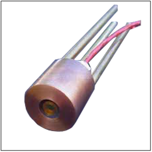
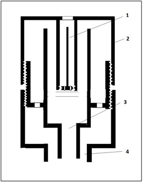
These losses associated with the optical system are eliminated in a radiometer in which the heat flux is determined from the temperature gradient of the sensitive element in the form of a metal rod. The sensing element is located in the water-cooled casing, the heat energy flow enters the sensing element through the opening, and the focusing lenses are absent. The measurement errors are related to the degree of blackness of the absorbing portion of the sensing element, the degree of blackness of the rod material (Figure 2 & 3).7

Figure 2Water cooled radio sensor of the Sensor TG9000 type. Measurement range up to 1000W/cm2; the time of measurement (inertia) to 0.5sec, the spectral range of sensitivity depends on the lens material (quartz - transparency 90%, range 0.3 - 3.0μm, Sapphire - transparency 90%, range 0.3-5.0μm, selenide zinc - a transparency of 70%, a range of 0.6-17.0μm).7

Figure 3 Design of the water-cooled sensor: 1 - sensor element - rod, 2 - sensor housing, 3,4 - water inlet and outlet.
As we know, the heat equation for a rod has the following form:
(1)
By measuring the steady-state temperature distribution in the rod, it is possible to determine the flow of thermal energy:
(2)
Here k is the coefficient of thermal conductivity, S is the cross section, T is the temperature, t is the time, c, ![]() is the heat capacity, the density of the material of the rod.
is the heat capacity, the density of the material of the rod.
A radiometer of this design is used at the Institute of Materials Science of the Scientific and Production Association "Physics-Sun" of the Academy of Sciences of Uzbekistan to measure the density of highly concentrated solar energy fluxes in the focal zone of the BSF.
It should be noted that equation (1) is in fact only an approximation, since there are no losses associated with the thermal conductivity and convection of air in the sensor housing, loss through radiation. Obviously, taking these factors into account can eliminate a systematic error in the flow measurements.
The heat equation in general form now has the form:
(3)
where is the loss function.
If we assume that the losses due to thermal conductivity are proportional to the temperature difference between the medium and the rod, heat transfer passes through the element of the rod surface, then is the radius of the rod.
The equation of thermal conductivity in the stationary case has the form:
(4)
The solution in this case is:
(5)
If it is assumed that the losses are carried out by radiant exchange between the rod surface and the water-cooled casing, then the loss function has the form:(6)
- the degree of blackness of the web material.(7)
Assuming that we have:(8)
The solution in the stationary case has the form:
(9)
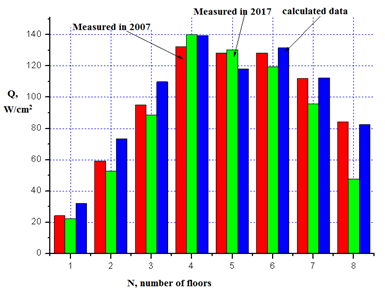
As we know, the BSP consists of 62 heliostats that are located on 8 floors. The energy contribution of each floor to the total energy is different. In Figure 4 shows calculated and measured using a radiometer in 2007 and 2017 energy characteristics from heliostats of the individual floors of the BSF.

Figure 4 Calculated and measured using a radiometer in 2007 and 2017 energy characteristics from heliostats of the individual floors of the BSF.
Figure 5 shows the measured values of light flux density distribution in the focal zone for different BSF floors. The data are reduced to a value corresponding to the incident direct solar radiation of 700 W/m2. Q - the light flux in a focal spot of diameter D = 40 cm. Q1 =23,55 кW; Q2 =44,77 кW; Q3 =58,55 кW; Q4=77,09 кW; Q5 =87,72 кW; Q6 =83,02 кW; Q7 =54,29 кW; Q8=18,28 кW.
As can be seen from expressions (5) and (9), when the losses are taken into account through radiation and thermal conductivity, an additional term inversely proportional to the radius of the rod appears. In our opinion, this fact can be used to improve the accuracy of measurements. Carrying out measurements with sensitive elements of different radii made from the same material, we can reduce the measurement errors associated with the degree of blackness of the material. Using the above formulas (4-9), we can form a calibration curve for the transition from mV to W/cm2 for the radiometer used, taking into account the features of the radiometer. Thus, the main advantage of this method is spectral non-selectivity. The small size and mass of the receiving surface in radiometers provide a low inertia and the possibility of obtaining detailed characteristics of the concentration field. Modern designs of radiometers with cooling of the measuring part allow measuring stably high levels of flux density up to 1.5 • 107 W/m2.
My research project was sponsored by Ministry of Innovation of the Republic of Uzbekistan with grant number (ИЗ-20170927404).
There is no conflict of interest.

©2018 Sobirov, et al. This is an open access article distributed under the terms of the, which permits unrestricted use, distribution, and build upon your work non-commercially.