Journal of
eISSN: 2572-8466


Research Article Volume 3 Issue 5
Department of Food Science and Technology, College of Food and Dairy Technology, India
Correspondence: Dhineshkumar V, Ph D Scholar, Food Technology, College of Food and Dairy Technology, TANUVAS.Chennai, India
Received: October 21, 2016 | Published: July 28, 2017
Citation: Dhineshkumar V, Ramasamy D. Review on membrane technology applications in food and dairy processing. J Appl Biotechnol Bioeng. 2017;3(5):399-407. DOI: 10.15406/jabb.2017.03.00077
The use of membrane technology as a processing and separation method in food industry is gaining wide application. Membrane separations can be used either as alternatives to conventional techniques or as novel technology for processing new ingredients and foods. Membrane separations are considered green technologies. In many cases, membrane processes are more advantageous than traditional technologies. For example, using cold pasteurization and sterilization with suitable membranes instead of high temperature treatment for the removal of microorganisms is more economical in terms of energy consumption. Using membrane filtration to remove microorganisms for shelf-life extension of foods instead of using additives and preservatives also create a green image for the processed foods as well as for the processing procedure. Concentration by membrane filtration instead of thermal evaporation does not employ severe heating and that it preserves the natural taste of food products and the nutritional value of heat-sensitive components. The recovery of valuable components in diluted effluents and wastewater treatment applications are among the most useful and currently active aspects of membrane technology. Pressure-driven membrane processes, namely MF, UF, NF and RO facilitate separation of components with a large range of particle sizes. It is for this reason that they find wide range of applications in food processing industry. The first part of this manuscript is to give introduction about very basic knowledge in membrane separation technology. More importantly, this review presents up-to-date commercial and potential applications of pressure-driven membrane separation processes in dairy processing industry.
Keywords: membrane separations, filtration, dairy, milk, cheese, whey
MFm, Micro Filtration; UF, ultra filtration; NF, nano filtration; RO, reverse osmosis; TMP, transmembrane pressure; CF, cross flow; DF, diafiltration; UTMP, uniform transmembrane pressure; NPN, non-protein nitrogenous; WPC, whey protein concentrate; WPI, whey proteins isolate; ED, electro-dialysis; MFGM, milk fat globule membrane; LAB, lactic acid bacteria
Theory of membrane separations
Pressure-driven membrane processes: The pressure-driven membrane processes include microfiltration (MF), ultrafiltration (UF), nanofiltration (NF), and reverse osmosis (RO). When a feed is introduced to a membrane separation system it is separated into retentate (sometimes called concentrate), the fraction that is retained by the membrane, and permeate (also called filtrate), the fraction that passes through the membrane. The products of interest can either be in the retentate or in permeate or in both streams. The word ‘pressure-driven’ means that the main driving force for separation of these processes is transmembrane pressure (TMP), which is the pressure discrepancy between retentate sides and permeate side. Generally speaking, the pore sizes (or MWCO-molecular weight cut-off in cases of NF and RO) of membranes decrease in the order from MF to RO (Figure 1). However, the separation principle is not based on the pore sizes alone. Especially in UF and NF the charge of the molecules/solutes and their affinity for the filtering membrane are also important.1 MF is normally used for separation of suspended particles and microorganisms from soluble components in feed. UF can be applied to separate soluble macromolecules such as proteins and peptides. NF is applied for partial demineralization and, at the same time, concentration. Basically, NF allows monovalent salts to pass through while it retains multivalent salts. Operational TMP values increase from MF to RO. For example, in MF applications the applied TMP is rarely higher than 3 bar. While those for UF are normally in range of 3-7 bar and for NF 10-30 bar. RO membranes, theoretically, allow only water to permeate. This means that RO processes works against chemical potential difference, namely osmotic pressure. For this reason, the operational TMP applied in RO is normally much higher (e.g., 10-75 bar) than in other pressure-driven separation processes. RO membranes, generally, reject 95% NaCl.
Definitions and terms: To be easier to follow the following parts of this manuscript, several common definitions and terms are given here. In dead-end filtration, which is normally applied in laboratory sample preparation, both pressure vector and feed flow are normal to the membrane while in crossflow (CF) or also called tangential filtration, the feed is pumped parallelly with the membrane and it is possible to recirculate the retentate back to the feed flow (Figure 2). Compared to dead-end filtration, CF filtration is, due to the tangential movement of the feed, characterized with lower extent of concentration polarizationand membrane fouling. These twophenomena are two major obstacles causing reduction in membrane separation performance. Concentration polarization expresses the raise-up in concentration of a macromolecular solute (retained by the membrane) at the surface of the membrane compared to that in the bulk phase. Membrane fouling indicates the deposition of solutes/particles on the surface (external fouling) and/or into the membrane pores (internal fouling).3,4 The components causing membrane fouling are called foulants. Diafiltration (DF) is carried out by diluting theretentate with a pure solvent, usually water or a buffer, and re-concentrating the diluted retentate. The main purpose of DF is to increase the purity of the membrane-rejected components (retentate components) and DF can be performed either in batch or in continuous manner.
Membrane separation parameters: A schematic diagram of a membrane separation unit with key parameters is illustrated in Figure 2. Other definitions along with the calculation formulas are given in Table 1.
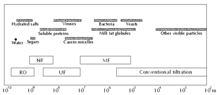
Figure 1 Approximate particle sizes and pressure-driven separation processes.2
Permeate flux |
Volume concentration ratio (VCR) |
| J
…………….(1) is effective surface area of the membrane |
VCR
……………..(2) - Feed volume at the beginning of operation - The retentate volume at time and - Permeate volume at time |
Average trans-membrane pressure (TMP) |
Transmission of component
, |
Apparent rejection which represents separation efficiency |
Selectivity of the membrane between two components
and
|
Table 1 Common definitions/parameters of membrane separation processes
Membrane characteristics and membrane modules
Membrane characteristics: Selection of a suitable membrane is very important determining the success of that specific application. Filtering membranes can be made from organic polymeric or inorganic materials. Organic membranes are generally available in a wide range of pore sizes, cheaper and normally have a high packing density (high membrane surface area/a unit of space volume). Among the disadvantages is that organic membranes, depending on materials, can only work in certain ranges of temperatures, pH, and TMP. Organic membranes are also more sensitive to washing chemicals too.5 In opposite, inorganic membranes (mostly made of ceramic material) can be operated in more extreme conditions, have longer service life. However, they are more expensive and the packing capacity is low. Ceramic membranes are normally fabricated into tubular modules and, so far, available for MF and UF. Membrane materials can be divided into two groups, hydrophilic and hydrophobic membranes. Depending on properties of the feed, a suitable membrane should be selected. For example to filter an aqueous solution of proteins at neutral pH, hydrophilic membranes are considered to be more advantageous over hydrophobic ones since negatively charged proteins are more repulsive against hydrophilic membranes resulting in less occurrence/lower extent of membrane fouling. Concerning structure, most of membranes are asymmetric. For instance, membranes are fabricatedinto two layers, a thin active layer being responsible for membrane selectivity and a thicker and more porous layer for physical support.
Membrane modules: The word ‘module’ expresses how membranes are arranged or packed. There are several types of membrane modules, namely plate-and-frame, tubular, spiral-wound, hollow-fiber, and membrane cassette. Different types of modules are different in packing density, possible applications, and price. The hollow-fiber and spiral-wound modules provide the largest packed membrane area per unit volume. While plate-and-frame and tubular modules have the lowest packing density, which means highest investment for a unit of membrane surface area. Tubular modules (ceramic membranes) are used widely in MF of skim milk. With this type of module, the feed channel is wide (e.g., from below 1 cm to 3 cm in diameter) so the feed can be pumped with high CF velocities, which help minimize the formation of concentration polarization and external membrane fouling and hence improve permeate flux and allow the retentate to be concentrated to a high level (higher VCR). Spiral-wound modules (diameters in range of 0.1 to 2 mm) are the most common design for RO and UF membranes.6
Enhancement of membrane separation performance
Fouling can, in many cases especially in MF and UF of poly dispersed feeds like milk, develop very quickly after the start of filtration, leading to a drop in permeate flux. A typical permeate flux evolution during CF filtration of a constant-concentration feed (e.g. both permeate and retentate are completely circulated back to the feed tank) is shown in Figure 3. Both the internal and surface foulants act as additional layers of resistance to the transmission of solutes through the membrane. Because of that, the selectivity of the membrane is modified. The occurrence and extent of concentration polarization and fouling depend on many factors including feed properties (Figure 4), membrane materials and structure, membrane modules, and operational parameters (Figure 4) such as temperatures, TMP values, and CF velocities.7-10 There are several techniques which can be applied to increase the membrane separation performance (improve permeate flux or prevent fast drop of permeate flux and maintain membrane selectivity). First, operational conditions should be optimized. It is not always true that increasing TMP results in increased permeate flux (Figure 4). The ‘best’ filtering conditions are the settings at which all sections (along the length) of the membrane work at the critical flux (Figure 4), the flux at which fouling starts to occur. The uniform transmembrane pressure (UTMP) configuration for tubular modules, patented by Alfa-Laval AB in Sweden.11 is a ‘breakthrough’ in development of membrane separation technology (Figure 5).
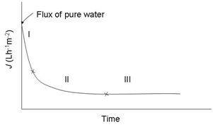
Figure 3 Typical flux evolution during CF membrane filtration of a constant-concentration feed.
In a conventional tubular module, fouling occurs with higher extent at the feed-in end of the membrane and selectivity is not the same along the membrane. In UTMP, co-current flow of permeate is applied to create pressure in the permeate side (Figure 5). Therefore, TMP can be adjusted independently with CF velocity and that the whole system is easy to set under optimal conditions, e.g. low UTP at high CF velocities, which lead to less compact fouling andvariation of selectivity along the membrane tube. Membralox® GP, which is commercialized by PALL Corp. (NewYork, USA) and Isoflux® by Tami Industries (Nyons, France) for MF applications are called ceramic graded permeability modules which are tagged as ‘third generation’ membranes. In these tubular systems, the ‘constant’ permeate rate along the membrane obtained by changes in the structure of the membranes, either by increasing the porosity of the support layer as in Membralox12 or decreasing the thickness of the selective layer along the membrane tubes.
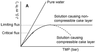
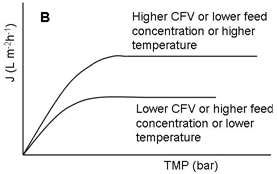
Figure 4 Profiles of permeate flux during filtration (e.g., MF and UF) of poly-dispersed solutions.
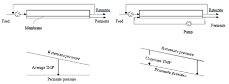
Figure 5 Module design and pressure profiles of TMP (left) and UTMP (right) filtration configuration.15
Permeate backflow techniques include backwashing ,3,13 backflushing,14,15 backpulsing,16 and backshock (backpulse with a reverseasymmetric membrane).17,18 An extra pump (hence require extra energy, more complicate control system) in the permeate pipe is needed to convert the TMP periodically during the operation and by that the backflow of the permeate lifts up the foulants which are then swept away by the crossflow of the retentate. The main differences of these methods are the applied frequency (e.g., backflow is applied periodically after a set time period during filtering), pressure discrepancy, and length of time for the permeate backflow. Backwashing involves using a third solution (e.g., water) as a backflow while others use the filtrate of the process. The backflow techniques help lengthen the filtration time before the permeate flux decreases to an unaccepted level and as such they reduce the frequency of chemical washings. Use of dynamic membranes19 or application of external forces like electric field and ultrasound,application of Gas/air sparging20 are other techniques for enhancement of membrane separation performance. The use of spacers (in organic polymeric membranes) and turbulence promoters (in tubular ceramic membranes to create turbulent flow at the surface of the membrane or to increase shear) also prove their efficiency in improvement of membrane separation performance in many cases.21-26 However, the introduction of spacer and turbulence promoters increase the drop of TMP along the membrane and in some cases the washing of the system after use becomes more challenging. Many of the enhancement techniques are industrially applicable while other are still under research and development phase. More information can be found in review papers7,27,28
Membrane processes in dairy industry
Milk, by nature, is a complicated and poly-dispersed system with suspended particles and soluble molecules having different charges and being in wide Milk, by nature, is a complicated and poly-dispersed system with suspended particles and soluble molecules having different charges and being in a wide range of sizes. The largest natural particles of milk are fat globules (1-15μm, with an average of around 3.5μm) and the following are casein micelles with average diameter of 0.4μm.2 Milk contains many more other components such as whey proteins, non-protein nitrogenous (NPN) compounds, lactose, minerals. As such, the use of any membrane types for processing of milk or dairy processing-derived streams becomes possible. This also means that the process performance is highly dependent on membrane materials, pH, temperatures and other operational parameters. Many discoveries on applications of membrane processing in food industry come from the dairy industry.29 The application trend went from the use of a membrane process in a single and separated processing step to the use of several membrane processes/types in several steps and in integrated production lines. Membrane processes can replace conventional processing methods. They can be implemented as innovative methods for the production of tailored-functionality ingredients in the development of new food products or improvement of existing food products.2 A downstream processing line of milk and the corresponding membrane processes involved at each level are shown in Figure 6. In the following subsections, the main applications of membrane processing in dairy industry and their advantages compared to corresponding conventional technologies are presented. The readers can refer to other reviews for more information.27,28

Figure 6 Membrane processes involved in the processing of milk to its purified groups.7
Separation and fractionation of milk fat globules
As mentioned earlier, fat in milk occurs in form of globules. For standardization of fat content in dairy processing, fat globules are separated from whole milk based on the difference in density between the two phases using a cream separator (a centrifuge). Technically, it is possible to use MF to separate fat globules from whole milk instead of using a cream separator.11 However according to our knowledge, there seems to be no industrial application of MF for this purpose yet. Several studies have been carried out to use MF of 5μm to fractionate milk fat globules based on their diameters.30 Yogurt and cheese made with smaller fat globules may have finer structure and other advantageous properties.30 Fat globules in milk are surrounded by a thin film, which is called milk fat globule membrane or MFGM, and this film is sensitive to mechanical impact and oxidation due to high concentration of phospholipids which are rich in unsaturated fatty acid.31 Therefore, application of MF to separate or fractionate milk fat globules need to take into consideration of those factors.
Membrane separations for removal of microorganisms
Membrane CF MF offers an efficient alternative to heat treatment for removal of bacteria from liquid food. Actually, removal of bacteria and spores from skim milk is one of the most important applications of MF in dairy industry. This technique is referred as cold pasteurization. Bactocatch process, developed by Alfa-Laval.32 and the patent now owned by Tetra Laval, as a milder pasteurization method employs a MF membrane of 1.4 μm, operated under UTMP condition. Typical operation conditions are UTMP of less than 0.5 bar and very high CF velocities of 6-8 ms-1.17,33 Bactocatch process isillustrated in Figure 7. First, cream is separated from milk using a cream separator. This is needed to increase the VCR while maintaining high permeate flux during the MF.36 The objective of the MF is to retain as much as possible bacteria and spores while letting milk components pass through the membrane. Common industrial permeate fluxes of MF in Bactocatch ranges from 500-800 L.h-1m-2, with VCR up to 20, proteins and total solids transmissions are about 99 and 99.5%, respectively. The operation time reaches 10h before membrane washing is needed.35 MF of skim milk with a 1.4 μm in the work of Elwell et al.34 resulted in a 3.79 log reduction in total bacteria and a further reduction of 1.84 log after the subsequent minimum pasteurization, leading to a total reduction of 5.63 log. Based on total microbial counts, the shelf life of this micro-filtered pasteurized milk when stored at 4.2 C was beyond 92 d but the real shelf life was limited to 42 d due to proteolysis.34 This is still much longer than the shelf life of normal pasteurized milk, which is about a week at refrigeration condition. High temperature, short-time (HTST) treated milk can last only up to 14 d due to spoilage bacteria. Ultra-pasteurization can extend the shelf life to 45 under refrigeration condition, however, this heat treatment already exert distinct cooked flavor, which is not acceptable to part of consumers.34,37 The prominent advantage of membrane filtration is that it can reduce bacteria to an accepted level while maintaining not only the typical flavor but also higher nutrition value of milk (due to less thermal impact). The other advantage of MF over thermal pasteurization is that the former can remove effectively spore-forming bacteria while the latter is aimed to destroy vegetative pathogens.
While the efficiency in removing total bacteria and spores is generally accepted, MF alone does not completely retain pathogens.35 That is why an extra minimum pasteurization after MF is needed in the Bactocatch process (Figure 7). Actually, MF with smaller pore sizes can remove pathogens more efficiently however the permeate flux and transmission of milk components is below the accepted levels. Bactocatch or MF, in general, can be applied in production of consumption (market) milk,17,34 preparation of milk for cheese production.35,38 and in removal of bacteria for production of low-heat-treated milk powders. In production of semi hard and hard cheeses like Gouda and Emmental, the incidence of ‘late-blowing’ defect (e.g., irregular eyes, slits, and cracks during ripening), caused by spore-forming Clostridium tyrobutyricum, during ripening is quite high and this phenomenon causes considerable production loss.39 Severe heat-treatment causes complexation between denatured whey proteins and caseins which affect subsequent coagulation process and flavor of ripen cheeses. Applications of Tetra Al cross Bactocatch system can, as claimed by the supplier, eliminate the risk of late-blowing defect without the necessity to use antibacterial additive in cheese production. Bacteria and fat removal from cheese brine for longer use is another potential application of MF.35
Fractionation of milk proteins for making cheeses, caseins and whey proteins and for milk protein standardization
Conventionally, cheeses are made from pasteurized milk (or raw milk of high quality for some special cheese products) by coagulating caseins using lactic acid bacteria and/or rennet enzymes. The whey is drained out and the curd is cut and washed. For manufacture of ripened cheeses, the curd is then molded, compressed, submerged in a brine solution, and put into a ripening room under suitable conditions in temperature and humidity for a period of time. In such a process, most whey proteins (e.g., -lactoglobulin, -lactalbumin, BSA) are ‘lost’ to the whey. MF membranes with pore size 0.1-0.2m can be used to fractionate skimmed milk into
The casein fraction can be used for vatless (e.g., no need of tank for cutting and washing the curd) production of semi-hard and hard cheeses or for production of casein-enriched ingredients without using acids to precipitate caseins and then other chemicals to neutralize the products.40-42 The volume of the retentate from the MF is much lower than that of the original milk and that the production of cheese from the retentate requires less quantity of rennet and additives, reduces total production time, increases capacity of the plant. MF production of cheese also allows flexible changing of the casein/whey protein ratio or the casein/fat ratio for desired structural and sensorial properties of final products. The 0.1-0.2μm MF permeate (microfiltrate), considered as sweet whey, contains the major whey proteins in highly functional (undenatured) state. Compared to classic cheese whey, the microfiltrate contains no rennet, bacteria, and starter culture, contains extremely low lipid content (i.e., <0.01%) and is more consistent in composition among production batches and different companies.41 This whey can be directly (without the necessity of clarification steps as for the whey from normal cheese making process) subjected to UF for manufacture of functionality-enhanced whey protein concentrate (WPC) and whey proteins isolate (WPI). The obtained powders have better oxidation stability due to a low concentration of lipids and has better technological properties e.g., gelling and foaming properties.41,43
UF can be used to standardize/concentrate milk for continuous production of cheeses. Not like MF, UF retains both caseins and whey proteins and that it increases cheese yield. It also reduces total processing time due to shorter clotting/coagulation time and elimination of several processing steps (such as curd cutting and whey drainage); and reduces the use of salt, starter culture, rennet and calcium chloride44,45. UF can be applied for production of cottage cheese, soft cheese varieties, some hard cheeses like Cheddar and Parmesan; the types of cheeses in which the presence of high concentrations of whey proteins does not create an issue in term of sensorial properties. The need of reduced fat cheeses increases due to the consumers’ awareness of health in relation to consumption of fat. With UF of skim milk, the retaining of whey proteins could regain (partially) the lost yield due to not using fat.46,47 Since long time, fat content is standardized in dairy industry. This is simply done by separating fat globules using a cream separator (centrifuge) and then reintroduced the cream back into the skimmed milk at desired concentrations. UF offers a reliable mean to standardize protein content for making of e.g., yogurt, cheese, ice cream and consumption milk without using thermal evaporation which causes protein denaturation leading to potential alteration of technological functionality and nutrition values and of the proteins.48 UF can be applied to produce milk protein isolate, a product has both caseins and whey proteins with the ratio similar to that in original milk but with low concentration of lactose and fat. This is an alternative to a process called coprecipitation (applying severe heat treatment to create interaction between caseins and whey proteins and then pH is lowered to precipitate the protein mixture). Milk protein isolate finds its applications in foods that require superior functionality such as confectionery and bakery products, infant foods, meat products, soups and sauces, dry seasoning blends, and cheese base for soft cheese making.
Treatment of whey for production of whey protein concentrate and whey protein isolate
Major part of commercial WPC and WPI are still produced from classic cheese whey.28 Classical cheese whey products contain, besides natural serum components of milk, substantially varied concentrations of remnants derived from cheese production process such as small fat globules, fragments of fat globule membranes, rennet enzymes, starter bacteria, caseinomacropeptides (this is the molecular parts of -casein molecules which are cut out from casein micelles by rennet).2 These remnants need to be removed before making WPC and WPI. The step assigned for this is called whey clarification and it is, traditionally, performed by pH adjustment and/or salt addition followed by gravity settling or centrifugation.49 Such clarification processes may not remove effectively phosphor lipoprotein complexes and very small milk fat globules. The presence of high concentration of the impurity affects adversely the functionality and storage stability of the whey products. For example, the presence of high concentration of fat, especially phospholipids, reduces the oxidation stability of the product as mentioned previously. MF is a very good alternative to the traditional clarification step and the former can be more advantageous not only because it retains fat more effectively but also bacteria and that the microfiltered whey does not need an extra pasteurization step, leading to higher quality of WPC or WPI. In conventional production of WPC from cheese whey, thermal evaporation is performed to increase solids content and then electrodialysis (ED) is applied to decrease mineral content. Although the desalination efficiency of NF is lower than that of ED, it can reduce salt content (monovalent salts like NaCl and KCl) while providing at the same time a concentration effect and that thermal evaporation is not needed.39
Integration applications of different membrane separation processes
From experimental results, Atra et al.49 proposed a procedure where two steps of UF in combination with NF are employed to obtain a more economical cheese production (Figure 8). In this process, the main target was to utilize whey. The first UF employs membrane of 6-8 kDa MWCO. The retentate of the second UF is introduced back into the cheese process, which can improve both the nutritional and economic values. The permeate solutions of both UF processes can be fed to a NF (400 Da MWCO) to concentrate lactose for sweet industry and the nana filtrate, containing low concentrations of organic material, can be reused in the production or for other purposes, representing a ‘‘cleaner” production.49 Targeting to consumers having lactose intolerance, reduced-lactose dairy products are produced using lactase, the enzyme which hydrolyzes lactose into glucose and galactose. Vyas et al.50 developed and tested on a pilot scale of a process using two steps of UF to produce a product called calcium fortified reduced lactose skim milk (Figure 9). Permeate of the first UF is treated by an increase in pH and/or a mild heat treatment to form and precipitate calcium complex which is then retained by the second UF. The combination of both increase in pH and heat treatment resulted in highest amount of calcium retained by the second UF. The retentate of this UF is then combined with the retentate of the first UF to give a skim milk product which is low in lactose and enriched with calcium).50 The second UF permeate can be used as a feed of NF for concentration of lactose, as proposed in (Figure 8).51 UF offer a very good opportunity to produce other low lactose dairy products such as milk beverages and yogurts.52
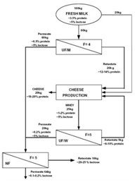
Figure 8 Proposed combination of UF and NF for a more economical cheese production. F represents VCR.49
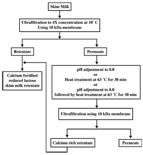
Figure 9 Flow diagram of the process for production of calcium fortified reduced lactose skim milk.50
Isolation of milk fat globule membrane materials
Milk fat globule membrane (MFGM), the membrane surrounding the milk fat globules, has received much attention recently due to the fact that it contains many components with health-beneficial properties.53 This small fraction of milk consists mostly of polar lipids, including phospholipids and sphigolipids, and specific-membrane proteins.54 Under certain treatments during dairy processing, MFGM is broken into fragments and these are distributed to aqueous streams. Therefore, buttermilk, butter serum, and whey from cheese production contain substantial amount of MFGM fragments. There are several possible ways to isolate these fragments (Figure 10). Buttermilk and butter serum contain caseins micelles and they should be dissociated into individual species (to be small enough to permeate the filtering membrane) or precipitated to remove before MF or UF in combination with DF can be applied to concentrate MFGM material.54 Considering the discussion in section 0 and this section, MF of cheese whey can be a dual target process; clarification and concentration of MFGM material. MFGM contains high concentration of polar lipids, which are amphiphilic molecules, so it can be used as an emulsifying agent.55 This material is as well a potential ingredient to develop functional food.56
Wastewater treatment
The dairy industry is considered as one of the most polluting food industries in term of water consumption and discharged volume of wastewater. Research on applications of membrane separation processes for treatment of wastewater is very active. NF applied to ultrafiltrate of whey has a twofold purpose; recovery of lactose from the retentate and reduction on volume of wastewater required to be treated at the plant since the nanofiltrate can be discharged directly into the sewer.2,13 Permeate of a single RO or a NF + RO operation could be reused as heating, cooling, cleaning and boiler feed water.57,58 Vourch et al.58 estimated that to treat 100 m3/d of wastewater from a dairy plant a 540 m2RO unit is required and that the water recovery could reach 95%. Purified water complying with drinking water criteria could be achieved by a two-stage RO + RO process treatment of dairy effluents.24,59,60,61
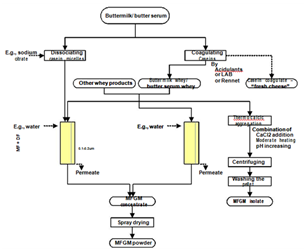
Figure 10 Various techniques and possible pathways for isolation of MFGM material from dairy industrial by-products.54
Since the introduction of membrane technology into the food processing industry about four decades back, the number of applications as well as the membrane surface area is increasing very fast. Some of the reasons for this trend include:
A more comprehensive understanding of membrane technology is continuously acquired and from these, additional techniques for increasing membrane process performance are being developed and optimized. Moreover, more and more membrane producers and scientists are now in search for cheaper and simpler methods of manufacturing membranes. All these factors are impetus in accelerating and extending the scope of membrane applications in the food industry.
None.
The author declares no conflict of interest.

©2017 Dhineshkumar, et al. This is an open access article distributed under the terms of the, which permits unrestricted use, distribution, and build upon your work non-commercially.