eISSN: 2574-8092


Research Article Volume 9 Issue 2
Department of Energy Engineering, ABC Federal University (UFABC), Brazil
Correspondence: Adas Pereira Vitalli Rogério, Department of Energy Engineering, ABC Federal University (UFABC), Brazil
Received: May 05, 2023 | Published: May 17, 2023
Citation: Rogério APV, Losada MJM. Nuclear engineering for monitoring the thinning of the pipe wall of the Angra 1 power plant. Int Rob Auto J. 2023;9(2):73-76 DOI: 10.15406/iratj.2023.09.00267
Large thermoelectric generation systems based on the Rankine cycle require monitoring of the thinning of the pipe wall caused by steam flow due to aging processes such as erosion and accelerated corrosion processes. Inspection difficulties are related to hostile environments (50 oC and 100% relative humidity) and spaces with complicated geometry, such as pipeline curves and their support structures. This work presents a monitoring program that integrates wall thickness inspections performed with a robotic system and Industry 4.0 technology to process the collected data and disseminate information throughout the organization. The robotic system is developed using “Digital Twin” technology, a very realistic virtual modeling scheme that allows interaction with the real world environment. They include equipment and all the steps to carry out the inspection process. The tube wall thickness monitoring system will be used at the Angra 1 nuclear power plant (Brazil).
Keywords: nuclear engineering, thickness measurement, Angra 1 (Brazil), digital twins, industry 4.0
Digital The Robotic System for Measuring the Wall Thickness of the Secondary Piping of the Angra 1 Nuclear Power Plant (SRME) is composed of 3 units. The first unit is a vehicle that can be operated remotely to allow displacement of the SRME to tubes of different diameters and allow thickness measurements. This unit is called Remotely Operated Vehicle Unit (UROV) for moving the SRME. The second unit is a robotic work cell indexed in the UROV, equipped with a robotic arm that performs the movements and inspection actions and that has installed the sensors that allow the movement to the measurement points and the external measurement of the thickness of the pipe wall. This unit is called the Thickness Measuring Robotic Cell Unit (UMRC). The third unit contains all other SRME systems such as power supply cables, data transmission cables, real-time information, computers and ancillary equipment. This unit is called the Communication, Power Supply and Ancillary Services Unit (UCPA). The industrial manipulator (robotic arm) must be able to access the external wall of the pipe and position the sensor located in the gripper appropriately to carry out the measurements. The thickness sensor used in this project is based on ultrasound. Other sensors that can be installed in the gripper are a video camera for vision or contact sensors and help the movement of the robotic arm and the correct positioning for carrying out the measurements. A “roboticist” (human operator) is also planned to provide the SRME with cognitive assistance for movement and inspection actions. The thickness measurement procedure is as follows: the UROV is moved and parked at certain locations. In these places, the robotic arm moves and performs inspection on the surface and all thickness measurement procedures.
The authors1 present a vehicle-handler system for inspection in an underwater environment composed of two subsystems: a remotely operated vehicle containing a manipulator support platform, a robotic arm containing a surface contact sensor in its end effector and the measurement sensor of the variable of interest. The robotic arm has a finite working area range and the inspection surface is typically much larger. To enable the inspection, the vehicle is moved to certain regions to cover the inspection surface. The system movement is decoupled into 2 parts: the vehicle and the robotic manipulator. To avoid human interaction, the movement of the vehicle to certain positions is carried out according to an algorithm based on “particle swarm optmization” (PSO). In these positions, the vehicle remains stationary and the movement to examine the surface is performed by the robotic arm using an algorithm based on “forward dynamic control” (FDO).
The authors2 present a robotic solution based on a vehicle-handler system for the automated collection of latex from rubber trees in which the vehicle travels on a rail positioned parallel to a row of rubber trees. The robotic system uses a vision system to determine the presence of a rubber tree stem. The system is an integration between hardware and software to operate in a specific forestry environment. The vehicle contains the platform that supports the robotic arm, industrial control computer and provides power for the system. The robot can handle 5 kg and has a reach of almost 1 m, the power is 800 W, the camera has a resolution of 480x640 and there are also contact and pressure sensors.
The authors3 present a platform that uses a drone for aerial inspection and maintenance of industrial installations and pipes exposed to the external environment. The industries involved are oil, gas, wind turbines, bridges and power lines. Oil, gas and refinery industries have thousands of miles of pipeline, with some sections difficult to access, requiring inspection and maintenance. The authors cite the European interest in this problem and one solution developed is a hybrid robot that can fly to the pipeline, land and move along it to reach different inspection points, using a small robotic manipulator arm with the ultrasonic sensor to reach the different measurement points around the tube diameter. The authors' proposal is a solution that flies to the point in the duct, attaches to it and from that condition performs the inspection by moving the robotic arm around the duct.
The digital twin6 is a concept of reproducing an environment, process or a single physical object first in the virtual world and then in the real world. The main objective is to map the main characteristics of the physical object or process, enabling digital validation, prediction and optimization in the areas of programming, systems maintenance,7,8 design, product manufacturing9–11 and processes.12 The main characteristics of the digital twin are: its shape, updateability, degree of precision with which it maps reality, anticipate problems, simulation and many others.13 In addition to areas such as: big data analysis, cloud computing, Internet of Things, artificial intelligence, automation, robotics, systems integration, additive manufacturing and augmented reality, digital twins are one of the elements of the Industry 4.0 concept.14,15 Robotics, and especially robotic manufacturing systems,16 is a specific area of digital twin applications. Numerous works refer to the use of digital twins in robotic engineering tasks,17‒20 issues of cooperation with people16 and issues related to predictive maintenance.21 Industrial robotics is also in the Industry 4.0 area due to the flexibility of automation, customization of solutions, adaptability, interaction with the environment and reconfiguration of advanced systems.22,24
This work proposal is divided into three parts: a) SRME – Robotic Thickness Measurement System. b) UMRC – Thickness Measurement Robotic Cell Unit. c) UROV – Remotely Operated Vehicle Unit.
SRME
The SRME project, from the point of view of increasing productivity (approximately 100,000 measurement points performed in 40 days of "STOP" with piping varying between 20 and 25 inches) in the execution of the entire process, it is desirable that the system has a communication interface with intelligence to handle the data in the manner established by Eletronuclear and that allows identifying possible locations with thicknesses closer to the acceptable limits or simply failures in the process of measuring the thickness of the pipe. In these cases, the robotic system can perform a sweep with more qualified inspection or repeat measurements.
UMRC
The UMRC project focuses on the detailed study of the AGV/DGS (Reflector Distance-Gain-Size) ultrasound technique, evaluating the reflector size, echo amplitude and signal height for more accurate detection of the discontinuity. The sensitivity of the reflector signal allows the indirect comparison of acoustic laws which has the great advantage of the possibility of dispensing with reference blocks. The AVG (Abstand Verstarkung Grosse) diagrams are: “general”, “normalized” or “special” according to the type of specific material in “Non-Destructive Tests”, mainly in ultrasound defined as volumetric test of mechanical waves in the frequency spectrum sound (below 20Hz: infrasound, up to 20KHz: sound and above 20KHz: ultrasound). Through piezoelectric crystals that convert electrical energy into mechanical energy and carry out the measurement of ultrasound waves by mechanical vibration that are transmitted into the material and then will reflect back to the crystal in a certain time that by deflection of the signal performs thickness measurement from the surface. Adopting ultrasonic pulse reflex principle, the measuring system is composed of transmission circuit, high-frequency oscillator, counter, central unit processor, keyboard and digital display. Similar to a light wave measurement, the sonic pulse occurs from the unit traveling through the material being measured until it reaches the interface and reflects back to determine the thickness of the material. To measure the axially thin parts that are not vertical to the surface, the area should not be too small, otherwise the measurement error may be high. However, when the material is a curved surface, such as the Angra 1 pipe wall, the radius of curvature must be greater than or equal to 10 mm, and the wall thickness must be greater than or equal to 3 mm. These requirements refer to steel-type material. In practice, the thickness of the piece to be measured is represented by the time between emission and reflection of the sonic signal. If there is a discontinuity (fault) in the material, that is, the reflected energy is less than the emitted one, there is a great variation in the amplitude of the wave, in time, the reflected distance of the wave and in the value of the thickness of the part, showing the discontinuity in the surface of material. The surface must always be clean, that is, free of scale, oxides, and any other impurities that may interfere with the coupling. This cleaning can be performed by brushing, sanding or grinding.
UROV
The UROV design must enable maximum access to measurement points. The vehicle's requirements are reduced size to allow access to the different measurement locations, mechanical strength and space to accommodate the systems of the other two units. From the visits made by the researchers to the Angra 1 plant where the pipes are located, it was concluded that the vehicle can be pushed by the SRME operators (roboticist) to the measurement points and have a locking system to the floor to present itself as a fixed and stable bench for the performance of the UMRC. Additionally, the UROV must enable movement via remote actuation for displacements on the x-y-z axes for the best positioning of the UMRC to perform thickness measurements.
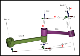
Robotic manipulators have positioning problems, speeds and forces applied in any type of movement. One of the most important activities of industrial robot control is the definition of its trajectory in three-dimensional space, which we call direct kinematics. To perform these movements, its joints need to move and to define these positions in spaces, we need to calculate the direct kinematics. According to,4 the Denavit-Hartenberg (DH) Notation is a systematic notation from the literature and used to assign to a robotic mechanism an orthonormal coordinate system according to the right-hand rule, one for each link in an open kinematic chain of links. Once these link-fixed coordinate systems are assigned, mathematical transformations between adjacent coordinate systems can be represented by a homogeneous coordinate transformation matrix. Figure 1 shows classic DH notation.

Figure 1 Classical Denavit-Hartenberg Notation.5
According to,5 in the original representation, the joint axis is associated with the Z axis and each matrix is represented by the product of four basic transformations involving rotations and translations, as we can see in Eq. (1).
(1)
The DH notation results in obtaining a 4x4 homogeneous transformation matrix, which transforms the coordinates of the system of link to the system of the previous link. With this, it is possible to express the transformation of coordinates from the “ ” system to the “ ” system, as we can see in Eq. (2).
(2)
In order to obtain the homogeneous transformation matrix that goes from the base of the robot to the extremity of the end-effector, we have to multiply all the transformation matrices obtained by Eq. (2), that is, the resulting matrix can be considered as the solution of the direct kinematics problem as we can see in Eq. (3).
(3)

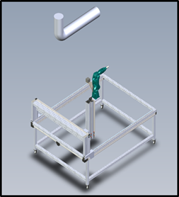
Figure 2 Complete SMRE system, containing the thickness measuring unit (URMC) and the remote unit (UROV).

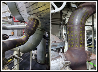
Figure 3 Angra 1 Systems Engineering determines the creation and formation of the GRID/MESH taking into account the diameter of the pipe, type of straight section (vertical/Horizontal) and type of curvilinear section (30, 45, 60, 90 or another value in degrees).

Figure 4 The UROV that allows movement in the field (Angra Turbine Building 1) by means of the robotist and also remotely in the x-y-z directions for better positioning of the robotic arm to perform thickness measurements.
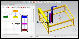
The methodology used to obtain the results of the direct kinematics of the robotic manipulator Yaskawa Motoman GP-7, used Denavit-Hartenberg (DH) notation for each joint of the robot. Then, these values were related through transformation matrices for the same axes. The resulting matrix T06 (Equation 3) can be considered as the solution of the direct kinematics problem, that is, the product of all the transformation matrices obtained through the modeling and simulation of the system. The GP-7 robot has a reach of 927 mm horizontally and 1693 mm vertically with a payload capacity of up to 7 kg, performing interpolated trajectories such as: JOINT, LINEAR, CIRCULAR and SPLINE.
To ensure that the prototype results are suitable for the effective use of SRME in Angra 1, all prototype design requirements must take into account the environment where thickness measurements take place in the Turbine Building. This article presents a work stage that considered important aspects of the Angra 1 power plant project. It was possible to model the virtual commissioning activities, transferring all the information and data of the project automatically to the physical project of the SRME. Access to the measurement sites occurs through two movements: the UROV and the UMRC. The UROV is moved by the roboticist to the closest possible location to the point of movement. From this point, via remote actuation, the roboticist can move the support base of the robotic arm in x-y-z by means of horizontal movements, x and y, and elevation, z. The second drive is provided by the UMRC robotic arm. This allows for greater access to the pipes. The movement of the support base of the robotic arm has a mathematical model with a telescopic concept of the z axis. Figure 4 showed the UROV with the remote operation system for x-y-z movement of the UMRC support base. There is a significant productivity gain in this process, as the entire programming of the physical robot, an important part of the project to carry out the process of measuring the thickness of pipes, is transferred directly from the virtual project (digital twin) to the real robot. The complexity of investigating the “causes” of failures by the mechanical process of wear by corrosion/erosion requires knowledge and concepts of “thermohydraulics.” For this, it is essential to equate the variables of oxygen, water pH, corrosion, time and temperature with the wear rate varying with the wear rate itself. For example, the pipe wall wore 4mm thick measured at the “FIRST STOP”. In the “SECOND STOP”, however, it wore 14 mm, that is, it is a lot of disparity caused by “thermohydraulic” agents that need to be investigated in more depth. The “History” of the measurement data of the thickness of the points is of great importance to compare with the measured data of the last “STOPS”.
The authors are grateful for the financial and technical support of Eletrobras Termonuclear SA– Eletronuclear, Amazônia Azul Tecnologias de Defesa SA and Fundação Parque de Alta Tecnologia da Região de Iperó –Fundação Pátria.
The author declares that there was no conflict of interest.

©2023 Rogério, et al. This is an open access article distributed under the terms of the, which permits unrestricted use, distribution, and build upon your work non-commercially.