In this paper an analysis of optical filter based on fiber-optic ring resonator using polarization and birefringence effects in the resonator loop is presented. The temperature variations, which affect the refractive index and radius of the ring, would cause a change in the filter response. The simulation results show that the resonant wavelengths would shift toward longer wavelengths and output intensity changes with increasing temperature. It is shown that for every 10 deg C change in temperature, would cause the resonance wavelength to increase by 0.1 .
Keywords: optical filter, tunability, fiber-optic ring resonator, thermo-optic tuning, wavelength, refractive index, resonator loop, Sagnac ring, fiber optic gratings, polarizing sensors, biosensors, dispersion compensating devices
Optical filters that are used today in fiber optic systems are designed based on various methods, such as fiber-optic ring resonator (FORR), Sagnac ring, fiber optic gratings, the use of arrayed waveguide gratings, or the use of dielectric thin-film interference structures and several other approaches. The tuning of these optical filters is also one of the key elements that should be taken into consideration, especially in WDM/DWDM optical communication systems, with channel spacing of less than 50 GHz. In this paper, the filter, which has been analyzed, is constructed on an FORR, with a resonance loop made up with a birefringent fiber.1 Today, FORRs are used for various applications such as polarizing sensors, biosensors, dispersion compensating devices, optical switches, and other applications used in optical communication systems such as biosensors,2 optical switching,3 add/drop multiplexers,4 micro disk laser resonators,5 simultaneous measurement of refractive index and temperature,6 optical Bistability,7 tunable optical filters,1,8 and several other applications used in optical communication systems. The use of FORR for tunable optical filters is analyzed, where the resonance loop of the FORR was made of photonic crystal fibers.9
A fiber-optic ring resonator with a resonance loop made of a conventional single-mode optical fiber as a nano-scale sensor for measurement of physical quantities, such as pressure and temperature is proposed.10 Recently, performance analyses of FORR under steady11 and dynamic12 states are reported, where the resonator responses in terms of characteristic parameters, are investigated. In our previous method, a Sagnac loop was used in an FORR to tune an optical filter which was based on variations of coupling coefficient and phase shift created by Sagnac rotation, and the fiber birefringence and propagating light polarization in the FORR. In this paper, we now want to study the effect of temperature variations on the filtering1 and analyze its tunability at different conditions.
In an FORR, any change that occurs on the structure and parameter of the loop, such as a change in loop radius and effective refractive index, makes the wavelength of the resonator change. One of the most important factors that change the radius of the FORR loop and the effective refractive index of the fiber is the temperature variations of the environment. Of course, the parameter that is more affected by the temperature changes is the effective refractive index of the fiber used in the FORR loop. The change in the wavelength of the FORR due to changes in the effective refractive index is given by the following equation:13
(1)
To justify the above relation, we consider an optical fiber with a certain cross-section with propagation constant β. We assume that this optical fiber carries a wave with frequency ω under the influence of an external factor such as the variation of environmental temperature q.
When we examine the output of the filter, two degrees of freedom
must be considered. The first one q is a minor change, then as a result, the propagation constant β changes as much as
and the resonance frequency is no longer ω. To revert the value of β to the original state, we change the frequency to reach the resonance condition, followed by a change
in β. The newly obtained frequency is considered to be tuned frequency. So, in general we have:
As a result, we have:
So, with the placement of the parameters, we have:
(2)
If this external factor
is due to temperature changes
, we will have:
(3)
Since the refractive index of the core differs from that of the fiber cladding, Eq. 3 changes as follows:
(4)
where the terms
and
are weighted coefficients that determine the amount of power in the corresponding region. These coefficients are calculated for each of the desired region as follows:
(5)
where
denotes the dielectric coefficient of the environment,
represents the group refractive index, and
is the refractive index of the region where the light wave penetrates. As a result, the refractive index of the core and the cladding regions change with respect to relative temperature variations as follows:
(6)
where
and
,
respectively, are weighted coefficients and refractive indices of the core and cladding, and
and
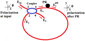
are corresponding thermo-optical coefficients. Different methods are used to calculate the thermo-optical coefficient of the fiber, among which interference is one of these methods.14 If we assume that fiber cladding is made of only pure silica and the fiber core is made with 15% mole combined with , the amount of thermo-optic coefficient will be 1.24 and 1.06, respectively. The schematic diagram of the fiber optic ring resonator is shown in Figure 1, where the incoming light wave enters the optical coupler with a definite polarization. By twisting the fiber on the xy-plane by the polarization rotator (PR) placed in the resonator loop, a circular birefringence is created in the fiber. Thus, in the resonator loop, two types of birefringence are created: one is a linear birefringence due to bending and the other is a circular birefringence caused by a twist. These two birefringences create phase differences of
and
in the light wave entering resonator loop. Thus, the total phase difference is expressed as follows:15
(7)

Figure 1 Schematic diagram of the Fiber optic resonator.1
PR, polarization rotator.
The x and y components of the normalized electrical fields just after PR are calculated as follows:
(8)
where for parameters
and
, respectively, we can write:
(9)
(10)
(11)
(12)
In the above expressions, k and α, respectively, are the coupling coefficient of the optical coupler and fiber transmission coefficient in the loop of the FORR. These two normalized electric fields are obtained by passing through the loop at the output of the filter as follows:
(13)
(14)
where
denotes the time delay of the FORR with the loop length of L and relative refractive index difference between the core and the cladding of
The fiber length is also increased by temperature variations. The longitudinal thermal expansion coefficient of fiber is equal to
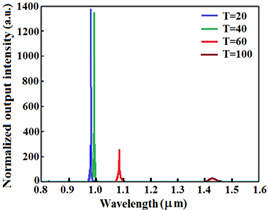
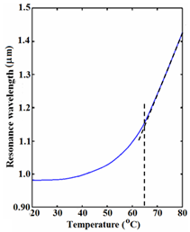
that is experimentally measured.16 Now, we introduce the temperature effects in corresponding Eqs. (3) to (6) in the normalized filter outputs expressed by Eqs. (13) and (14). If we choose the radius of the resonator ring at 15 and assume that the fiber is twisted through an angle 45 deg., thus the normalized output of the filter for different temperatures is obtained, as shown in Figure 2. As shown in Figure 2, when temperature increases, the resonance wavelength of the filter moves toward longer wavelengths. In Figure 3 the displacement of the resonance wavelengths at various temperatures from 20 to 80°C is indicated by a step of 10 degrees. At about 65°C onwards, the resonance wavelength varies linearly with respect to temperature changes. As the temperature increases, the output intensity considerably decreases. A temperature increase of 20 °C from 40 °C to 60°C, would cause normalized output intensity drop down from 1400 to about 260.

Figure 2 Normalized filter output for various temperatures from 20 °C to 100 °C.

Figure 3 The effect of temperature on resonance wavelength of the filter.


