The matrix state equations [8, 11‒17] of a piezo engine have the form
where
,
,
,
are the matrices of electric induction, relative deformation, mechanical field and electric field stresses, and t is transpose operator. For PZT engine the matrices have the form
The equation of the reverse piezo effect [8‒51] has the form
where m, i, j are axises.
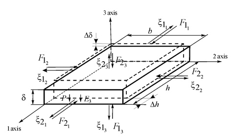
For the longitudinal piezo engine on Figure 1 its parameters are determined in the form

Figure 1 A piezo engine for composite telescope.
,
At
= 4∙10‒10 m/V,
= 0.8∙105 V/m,
= 2.5∙10‒3 m,
= 1.5∙10‒4 m2,
= 15∙10‒12 m2/N its maximum values of deformation and force are received in the form
= 80 nm,
= 320 N with error 10%.
The differential equation for a piezo engine has the form11‒51
where
,
,
are coordinate, operator and coefficient.
Its solution has form
For the stresses acting on two faces a piezo engine its transforms of Laplace have the form
where
or
.
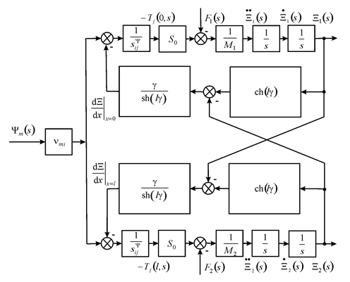
For the structural model and scheme of a piezo engine for composite telescope on Figure 2 its equations have the form

Figure 2 Structural scheme of a piezo engine for composite telescope.
where
,
,
,
,
,
,
,
is the piezo coefficient.
Therefore, the matrix equation of a piezo engine has the form
The steady‒state displacements of faces 1 and 2 for the longitudinal piezo engine have the form
At
= 4×10‒10 m/V, U= 250 V,
= 1 kg and
= 4 kg its displacements are obtained
= 80 nm,
= 20 nm,
= 100 nm with error 10%.
For the transverse piezo engine at elastic‒inertial load the expression has the form
,
where
,
are the stiffness of load and engine,
,
,
are the time constant, the attenuation coefficient and the conjugate frequency of the engine. At M= 3 kg,
= 0.2×10⁷ N/m,
= 1×10⁷ N/m its parameters are determined in the form the time constant
= 0.5×10‒3 s and the conjugate frequency of the engine
= 2×10³ s‒1 with error 10%.


