
Research Article Volume 2 Issue 4
Effects of lubrication on the steady oblique stagnation–point flow of a couple stress fluids
EKhalid Mahmood, Muhammad Sajid, Muhammad Noveel Sadiq,
Regret for the inconvenience: we are taking measures to prevent fraudulent form submissions by extractors and page crawlers. Please type the correct Captcha word to see email ID.

Nasir Ali
Department of Mathematics and Statistics, International Islamic University, Pakistan
Correspondence: Muhammad Noveel Sadiq, Department of Mathematics and Statistics, International Islamic University, Islamabad 44000, Pakistan, Tel 9251 9019 756
Received: November 22, 2017 | Published: August 28, 2018
Citation: Mahmood K, Sajid M, Sadiq MN, et al. Effects of lubrication on the steady oblique stagnation–point flow of a couple stress fluids. Phys Astron Int J. 2018;2(4):389-397. DOI: 10.15406/paij.2018.02.00115
Download PDF
Abstract
Steady oblique stagnation–point flow of a couple stress fluids on a flat plate is investigated numerically by implementing a well reputed Keller–box method. The plate is lubricated with a slim coating of power–law fluid. Governing partial differential equations of couple stress fluid are converted into ordinary differential equations using similarity transformations. Analysis has been performed by imposing continuity of velocity and shear stress of both the fluids at the interface. Influence of slip and couple stress parameters on the horizontal and shear velocity components, wall shear stress and stagnation point are presented graphically and in the tabular form. The limiting cases for the viscous fluid and no–slip condition have been deduced from the present solutions. The results are compared with already recorded results in the existing research articles and are found in excellent agreement.
Keywords: couple stress fluid, oblique stagnation–point flow, power–law lubricant, continuity of shear stress and velocity, keller–box scheme.
Introduction
Flow of non–Newtonian fluids has attracted attention of many scientists and researchers because of their fundamental and practical importance in the industry as well as in the daily life. Shear stress of such fluids is non–linearly related with shear rate and it is very difficult to analyze their flow. Examples include food, rubber, gel, polymers, petrol, paper coating, plasma and grease etc. One such fluid is the power–law fluid (Ostwald–de Waele model) which has been used extensively in the industry especially as a lubricant.
Couple stress fluid is another important non–Newtonian fluid first examined by Stokes1 to describe the polar effects. The couple stress fluid can be described by a new type of tensor called couple stress tensor in addition to the Cauchy stress tensor. In such fluids, polar effects play a significant role which are present due to the couple stresses (moment per unit area) and body couples (moment per unit volume). Because of significant importance of couple stress fluids in the industrial and engineering applications, many researchers have analyzed these flows. Some applications are animal blood, liquid crystals, polymer thickened oil, fluid mechanics and polymeric suspensions. Devakar et al.,2 considered Stokes’ problems for the couple stress fluid. In another investigation, Devakar et al.,3 discussed properties of the couple stress fluid flowing between parallel plates. Heat transfer analysis for the flow of a couple stress fluids near a stagnation point has been carried out by Hayat et al.,4 Muthuraj et al.,5 studied viscous dissipation effects on MHD flow of a couple stress fluid in a vertical channel. Heat transfer analysis by Srinivasacharya et al.,6 has been carried out for couple stress flow due to expanding and contracting walls in a porous channel. Flow of couple stress fluid due to free convection through a porous channel was carried out by Hiremath and Patil7. Umavathi et al.,8 discussed heat transfer analysis for the channel flow of a couple stress fluid sandwiched between two viscous fluids. They showed that couple stress parameter is responsible for enhancing the fluid velocity.
A literature survey reveals that stagnation–point flow can be discussed in two ways either orthogonally or obliquely. Hiemenz9 provided an exact solution of stagnation–point flow for the first time. An oblique stagnation–point flow arises when a detached flow of fluid retouches the face of body. Non–orthogonal stagnation–point flow on a wall was examined by Stuart10 and Tamada11. Dorrepaal12 found an exact solution for the oblique stagnation–point flow of a viscous fluid. Effects of Weissenberg number on the flow and heat transfer due to stagnation–point was analyzed by Li et al.13 Labropulu et al.,14 discussed heat transfer analysis for the oblique flow impinging on a stretched sheet. Axisymmetric non–orthogonal stagnation–point flow over a circular cylinder has been considered by Weidman and Putkaradze15. Recently Ghaffari et al.,16–18 discussed different aspects for the flows towards oblique stagnation point.
Wang19 discussed the effects of slip parameter on the stagnation point flow of a viscous fluid. Devakar et al.,20 found an exact solution for a couple stress fluid by implementing slip condition at fluid–solid interface. Labropulu et al.,21 examined slip flow due to second grade fluid impinging orthogonally or obliquely on a surface. Blyth & Pozrikidis22 studied stagnation point flow by introducing slip condition at the interface of two viscous fluids. Axisymmetric stagnation–point flow near a lubricated stationary disc has been carried out by Santra et al.23 They used power–law fluid as a lubricant. Sajid et al.24 reconsidered the problem of Santra et al.,23 by applying generalized slip condition at fluid–lubricant interface introduced by Thompson & Troian.25 Recently Mahmood et el.,26 investigated oblique stagnation–point flow of a second–grade fluid over a plate lubricated by a power–law fluid. Some more recent investigations27–32 will also be fruitful for the readers.
Our aim in the present communication is to investigate the oblique flow of a couple stress fluids near a stagnation point over a lubricated plate. A power–law fluid has been utilized for the lubrication purpose. The flow problem consists of the set of coupled nonlinear ordinary differential equations along with nonlinear coupled boundary conditions. The Keller–box method33–36 has been implemented to solve the considered flow problem numerically. Influence of pertinent parameters on the flow characteristics is discussed through graphs and tables. The validity of present study has been checked by comparing results in the limiting case with that exist in the literature.
Mathematical formulation
Consider the steady, two–dimensional, oblique flow of a couple stress fluids towards a stagnation point over a lubricated plate. A power–law fluid (Ostwald–de Waele model) is used as lubricant. The plate is fixed in xz–plane such that it is symmetric with respect to origin. The fluid impinges on the plate with an angle in the domain (Figure 1).
We assume that power–law lubricant spreads on the plate forming a thin coating with the flow rate given as
(1)
where
represents horizontal velocity component of the lubricant and denotes the variable thickness of the lubrication layer.
The flow problem is governed by the following equations37
(2)
(3)
(4)
where u and vrepresent, respectively horizontal and vertical velocity components of the couple stress fluid. Parameters ,
,
and respectively are density, pressure, kinematic viscosity and ratio of couple stress viscosity to the density.
Following Tooke & Blythe38 the free stream velocity components can be written as
(5)
where a and b are constants. Furthermore
is the parameter that supervises the pressure gradient along x–axis which generates the shear flow incident to the orthogonal stagnation–point and the parameter
represents the boundary layer displacement produced on the lubricated surface. It is worth to mention that the flow field (5) displays the combined effects of both the horizontal shear flow and the orthogonal stagnation–point flow.
Eliminating the pressure between Eqs. (2) and (3) one obtains
(6)
The expression for the skin friction or wall shear stress is given as
(7)
where
and are viscosity and couple stress viscosity respectively. The usual no–slip boundary condition at the solid–lubricant interface implies
(8)
As the power–law coating is very slim, therefore
(9)
We assume that velocity and shear stress of both the fluids are continuous at the interface
Thus continuity of shear stress implies
(10)
In which represents the viscosity of the lubricant. Letting the viscosity of lubricant can be written as
(11)
in which
is dynamic coefficient of viscosity and
is the consistency index. Fluid behaves as viscous, shear thinning and shear thickening, respectively for
and
.
We further assume that
(12)
It is worth to point out that
is interfacial velocity component of both fluids. The thickness
of the power–law lubricant is given by
(13)
The continuity of horizontal velocity components of both the fluids gives
(14)
Substituting Equations (11)–(14) in Equation (10) we get
(15)
Similarly implementing the continuity of interfacial velocity components of bulk fluid and lubricant along y–axis we get
(16)
Employing Equation (9) we get
(17)
Following Santra et al.,23 the boundary conditions (15) and (17) can be imposed at the fluid–solid interface. Boundary conditions at free stream have been mentioned in equation (5).
Introducing
(18)
The governing Equations (6), (8), (15), and (17) reduce to
(19)
(20)
(21)
(22)
(23)
Where
is called the couple stress parameter and
denotes the free stream shear. The parameter
in Equations (21) and (22) is given as
(24)
Integrating Equations (19) and (20) and using free stream conditions, we get
(25)
(26)
Where
is a free parameter and
. In order to eliminate
from Equation (26)we let
to obtain
(27)
The boundary conditions in new variables become
(28)
Equation (24) suggests that to obtain similar solution, one should have
. The parameter
given in Equation (24) measures slip produced on the surface and can be written as
(29)
As clear from Equation (29),
is a representation of ratio of viscous length scale
to the lubrication length scales
. For a highly viscous bulk fluid (i.e. when
is large) and a very thin lubricant (i.e. when
is small), the parameter
is increased. As the parameter
approaches to infinity, the traditional no–slip conditions
, andcan be recovered from Equations (21) and (28). On the other hand when the bulk fluid is less viscous and
attains a massive value,
and consequently the full slip boundary conditions , and are achieved.Therefore
interprets the inverse measure of slip called slip parameter.
Employing (18), the dimensionless wall shear stress is given by
(30)
To find the stagnation–point
on the surface, we set
Therefore
(31)
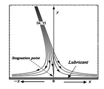
Figure 1 Reported bird strikes and parts mostly hit(* FAA wildlife strike data base).
Numerical method (the keller–box method)
Equations (21), (25), (27) and (28) are solved using Keller–box method33–36 which is based on an implicit finite difference approach. This numerical scheme is very effective to solve non–linear and coupled boundary value problems directly without converting them into initial value problems. As a first step, a system of first order ordinary differential equations is obtained in the following way:
(32)
Therefore, Equations (25) and (27) imply
(33)
The transformed boundary conditions n=0.5 for imply
(34)
(35)
The obtained first–order system is approximated with central–difference for derivatives and averages for the dependent variables. The reduced algebraic system is given by
, ,, , (36)
, , (37)
(38)
(39)
where
etc. Equations (38) and (39) are nonlinear algebraic equations and therefore, have to be linearized before the factorization scheme can be used. We write the Newton iterates in the following way:
For the
iterates:
(40)
for all dependent variables. By substituting these expressions in Equations (36)–(39) and dropping the quadratic and higher–order terms in
, a linear tridiagonal system of equations will be obtained as follows:
(41)
(42)
(43)
(44)
(45)
(46)
subject to boundary conditions
(47)
(48)
where
etc. The resulting linearized system of algebraic equations is solved by the block–elimination method. In matrix–vector form, the above system can be written as
(49)
in which
(50)
where the elements inA are of matrices and that of and are respectively of order
. Now, we let
(51)
where L is a lower and U is an upper triangular matrix.
Equation (51) can be substituted into Equation (49) to get
(52)
Defining
(53)
Equation (52) becomes
(54)
where the elements of are
column matrices. The elements of
can be solved from Equation (54). Once the elements of
are found, Equation (53) then gives the solution. When the elements of
are found, Equation (49) can be used to find the next iteration.
Numerical results and discussions
The values of
and
are displayed graphically for different values of , and and
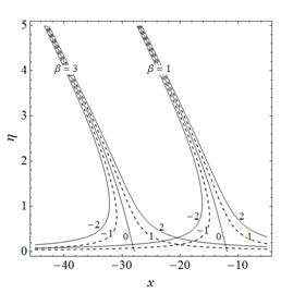
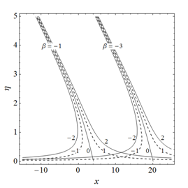
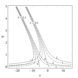
are presented in Figures 2–6. The influences of pertinent parameters on the streamlines have been shown in Figures 7–8 while the impact of these parameters on,, and stagnation points are displayed in Tables 1–5. The comparison of numerical values of , and
in the special cases with that of existing in the literature are presented in Tables 6–7.
Figure 2 displays the variation in horizontal velocity component under the influence of slip parameter . Dashed lines show the results for viscous and solid lines for the couple stress fluid. We observe that
decreases by decreasing
. Moreover, couple stress parameter enhances the effects of slip parameter. Analysis showing the impact of couple stress parameter k on
for fixed
is presented in Figure 3. It is clear from this figure that
is an increasing function of k. We observe some alteration inside the boundary layer. However, the curve becomes smooth at the free stream. Effects of slip parameter
on
for two values of
when
have been provided in Figure 4. According to this figure decreases for positive values of and increases for negative values of . Figure 5 is displayed to analyze the behavior of under the influence of both for the no–slip and partial slip cases. It is noted that an increment in the value of
results in the decrease of
. This decrease is more significant on the rough surface (when
). Influence of parameter on
for two values of k when
is presented in Figure 6. The analysis shows that
decreases by increasing
.This decrease is diminished by enlarging couple stress parameter k.
The streamlines explored in Figure 7 show the influence of on the stagnation point in the presence of slip when . It has been observed that the stagnation point moves towards left by increasing . Streamlines showing the impact of slip and couple stress parameters are expressed in Figure 8. It is evident that stagnation point shifts towards right by increasing as well as k when
.
Influence of parameters and k on the skin friction coefficient and boundary layer displacement has been provided through Table 1. It is observed through Table 1 that increases by increasing and decreases by increasing k. Likewise, is increased by enhancing and k independently.Impact of on is shown in Table 2. It has been observed that gains the magnitude by enhancing for and loses for . Data showing for various values of k is represented through Table 3. It is observed that gains the magnitude as k is accelerated for and loses its values for . The movement of the stagnation point under the influence of increasing ,k and
is demonstrated through Tables 4–5. We observe that stagnation point moves towards right on the x–axis by raising both and K while it shifts leftwards by augmenting . The tabular results shown in Tables 4–5 do confirm the investigations made through Figures 7–8.
The numerical data regarding , and in the limiting case (when ) acknowledges the values already recorded in the research articles.13,14 This evidence certifies the correctness of our investigation.

Figure 2 Effects of slip parameter
on for viscous and couple stress fluids.
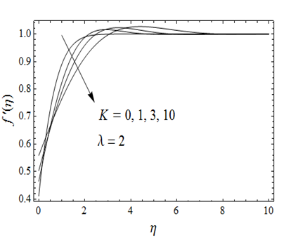
Figure 3 Impact of couple stress parameter k on when .

Figure 4 Influence of slip parameter
on when for two different values of
.
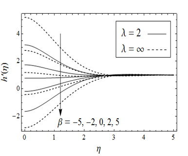
Figure 5 Influence of parameter
on when for two different values of .
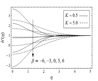
Figure 6 Influence of parameter
on when
for different values of k.
(A)
(B)
Figure 7 Streamlines showing the effects of parameter
.
-
(A)

(B)
Figure 8 Influence of slip parameter and couple stress parameter on streamlines.
|
|
|
|
|
|
|
|
|
|
|
0.05 |
0.024513 |
0.016329 |
0.011422 |
0.018947 |
0.008514 |
0.020793 |
0.1 |
0.047914 |
0.032162 |
0.022481 |
0.037498 |
0.016793 |
0.041183 |
0.5 |
0.201357 |
0.142545 |
0.099287 |
0.172333 |
0.075344 |
0.1903459 |
1.0 |
0.331885 |
0.24714 |
0.171830 |
0.310541 |
0.132596 |
0.345523 |
2.0 |
0.482678 |
0.384176 |
0.266567 |
0.510465 |
0.210874 |
0.575286 |
5.0 |
0.645204 |
0.559482 |
0.385209 |
0.801933 |
0.315692 |
0.923349 |
10 |
0.717872 |
0.651212 |
0.444105 |
0.969866 |
0.370759 |
1.130525 |
50 |
0.782587 |
0.742733 |
0.498917 |
1.145315 |
0.423622 |
1.350408 |
100 |
0.791011 |
0.755479 |
0.506158 |
1.170181 |
0.430701 |
1.381723 |
500 |
0.797793 |
0.765898 |
0.511999 |
1.190562 |
0.436424 |
1.407399 |
|
0.799494 |
0.768534 |
0.513465 |
1.195725 |
0.437862 |
1.413905 |
Table 1 Variation in and under the influence of
.
|
|
|
|
0.05 |
0.429505 |
0.307015 |
0.551994 |
0.1 |
0.443315 |
0.203884 |
0.682746 |
0.5 |
0.542598 |
–0.463751 |
1.548947 |
1.0 |
0.641277 |
–1.017849 |
2.300403 |
2.0 |
0.776652 |
–1.637394 |
3.190698 |
5.0 |
0.958302 |
–2.270844 |
4.187448 |
10 |
1.056333 |
–2.537892 |
4.650558 |
50 |
1.155641 |
–2.764100 |
5.075382 |
100 |
1.169566 |
–2.792576 |
5.131708 |
500 |
1.180963 |
–2.815320 |
5.177246 |
|
1.183848 |
–2.820999 |
5.188695 |
Table 2 Variation in under the influence of and when
.
|
|
|
|
0 |
0.540232 |
–2.427089 |
3.507552 |
0.5 |
0.641277 |
–1.017849 |
2.300403 |
1 |
0.670213 |
–0.749052 |
2.089478 |
5 |
0.770745 |
–0.152261 |
1.693750 |
10 |
0.834636 |
0.138111 |
1.531161 |
50 |
0.949295 |
0.709083 |
1.189507 |
100 |
0.972800 |
0.840434 |
1.105165 |
500 |
0.994183 |
0.965210 |
1.023155 |
5000 |
0.999406 |
0.996439 |
1.002374 |
Table 3 Variation in under the influence of and when
.
|
|
|
|
|
1 |
0.5 |
2.558763 |
–0.4412284 |
–3.441220 |
5.0 |
3.197895 |
0.1979019 |
–2.802092 |
2 |
0.5 |
5.117527 |
–0.8824568 |
–6.882440 |
5.0 |
6.395791 |
0.3958038 |
–5.604183 |
5 |
0.5 |
12.79382 |
–2.2061420 |
–17.20610 |
5.0 |
15.98948 |
0.9895095 |
–14.01046 |
8 |
0.5 |
20.47011 |
–3.5298270 |
–27.52976 |
5.0 |
25.58316 |
1.5832150 |
–22.41673 |
Table 4 Variation in the stagnation point
under the influence of parameters of , and when
.
|
|
|
|
|
1 |
0.5 |
2.667206 |
–0.3327937 |
–3.332794 |
5.0 |
2.870132 |
–0.1293493 |
–3.128831 |
2 |
0.5 |
5.334413 |
–0.6655873 |
–6.665587 |
5.0 |
5.740265 |
–0.2586985 |
–6.257662 |
5 |
0.5 |
13.33603 |
–1.6639680 |
–16.66397 |
5.0 |
14.35066 |
–0.6467463 |
–15.64415 |
8 |
0.5 |
21.33765 |
–2.6623490 |
–26.66235 |
5.0 |
22.96106 |
–1.0347940 |
–25.03065 |
Table 5 Variation in the stagnation point
under the influence of parameters of ,and
when
|
|
Present result when
|
Result by Labropulu et al.14 when
|
Present result
when
|
Result by Labropulu et al.14
when
|
1.232594 |
1.23259 |
0.6479025 |
0.64790 |
Table 6 Comparison of computed results of and
with that of Labropulu et al.14 for no–slip case (
).
|
|
|
|
|
Present results when
|
–4.756217 |
1.406514 |
2.205136 |
0.607917 |
Results by Labropulu et al.14 when
|
−4.7562 |
1.4065 |
2.2051 |
0.6079 |
Results by Li et al.13 when
|
−4.756 |
1.4063 |
2.2049 |
0.6077 |
Table 7 Comparison of computed results of
with that of Li et al.13 and Labropulu et al.14 for no–slip case (
).
Conclusion
In this paper, oblique flow of a couple stress fluids near stagnation point over a lubricated plate is investigated. A power–law fluid has been used as a lubricant. To obtain similar solution of the flow problem, we have fixed . The Keller–box method is employed to solve the flow problem numerically. Our interest is to figure out the effects of free parameterand couple stress parameter k on the flow characteristics on the lubricated surface. Obtained results in the special case are compared.13,14 It has been concluded that:
- Slip produced on the surface increases the velocity of the bulk fluid and abolishes the effects of free stream velocity for large values.
- The stagnation point is shifted towards right and left along –axis under the influence of physical parameters in the presence of lubrication.
- The skin friction coefficient increases by increasing and decreases by increasing k. However boundary layer displacement is increased by enhancing
and/or k .
- It has been observed that
gains the magnitude by enhancing
for
and loses for .Data showing
for various values of k is represented through Table 3. It is observed that
gains the magnitude as k is accelerated for
and loses its values for
.
Acknowledgements
None.
Conflict of interest
Author declares there is no conflict of interest.
References
- Stokes VK. Couple stresses in fluids. Physics of Fluids. 1966;9(9):1709–1715.
- Devakar M, Iyengar TKV. Run up flow of a couple stress fluid between parallel plates. Non–linear Analysis: Modelling and Control. 2010;15(1):29–37.
- Devakar M, Iyengar TKV. Stokes’ problems for an incompressible couple stress fluid. Non–linear Analysis: Modelling and Control. 2008;1(2):181–190.
- Hayat T, Mustafa M, Iqbal Z, et al. Stagnation point flow of couple stress fluid with melting heat transfer. Applied Mathematics and Mechanics. 2013;34(2):167–176.
- Muthuraj R, Srinivas S, Immaculate DL. Heat and mass transfer effects on MHD fully developed flow of a couple stress fluid in a vertical channel with viscous dissipation and oscillating wall temperature. International Journal of Applied Mathematics and Mechanics. 2013;9:95–117.
- Srinivasacharya D, Srinivasacharyulu N, Odelu O. Flow and heat transfer of couple stress fluid in a porous channel with expanding and contracting walls. International Communications in Heat and Mass Transfer. 2009;36(2):180–185.
- Hiremath PS, Patil PM. Free convection effects on the oscillating flow of a couple stress fluid through a porous medium. Acta Mechanica. 1993;98:143–158.
- Umavathi JC, Chamka AJ, Manjula MH, et al. Flow and heat transfer for a couple stress fluid sandwiched between viscous fluid layers. Canadian Journal of Physics. 2005;83(7):705–720.
- Hiemenz K. Die Grenzschicht an einem in den gleichformingen Flussigkeitsstrom eingetauchten graden Kreiszylinder. Dinglers Polytech Journal. 1911;326:321–324.
- Stuart JT. The viscous flow near a stagnation–point when the external flow has uniform vorticity. Journal of the Aerospace Sciences. 1959;26;124–125.
- Tamada KJ. Two–dimensional stagnation–point flow impinging obliquely on a plane wall. Journal of the Physical Society of Japan. 1979;46:310–311.
- Dorrepaal JM. An exact solution of the Navier–Stokes equation which describes non–orthogonal stagnation–point flow in two dimensions. Journal of Fluid Mechanics. 1986;163:141–147.
- Li D, Labropulu F, Pop I. Oblique stagnation–point flow of a viscoelastic fluid with heat transfer. International Journal of Non–Linear Mechanics. 2009;44:1024–1030.
- Labropulu F, Ghaffar A. Oblique Newtonian fluid flow with heat transfer towards a stretching sheet. Computational Problems in Engineering. 2014;307:93–103.
- Weidman PD, Putkaradze V. Axisymmetric stagnation flow obliquely impinging on a circular cylinder. European Journal of Mechanics. 2003;22(2):123–131.
- Ghaffari T, Javed, Labropulu F. Oblique stagnation point flow of a non–Newtonian nanofluid over stretching surface with radiation: A numerical study. Thermal Science. 2015;21(5):2139–2153.
- Javed T, Ghaffari A, Ahmad H. Numerical study of unsteady MHD oblique stagnation point flow with heat transfer over an oscillating flat plate. Canadian Journal of Physics. 2015;93(10):1138–1143.
- Ghaffari A, Javed T, Majeed A. Influence of radiation on non–Newtonian fluid in the region of oblique stagnation point flow in a porous medium: A numerical study. Transport in Porous Media. 2016;113(1):245–266.
- Wang CY. Stagnation flows with slip: Exact solution of the Navier–Stokes equations. Zeitschrift für angewandte Mathematik und Physik ZAMP. 2003;54(1):184–189.
- Devakar M, Sreenivasu D, Shankar B. Analytical solution of couple stress fluid flows with slip boundary condition. Alexandria Engineering Journal. 2014;53(3):723–730.
- Labropulu F, Li D. Stagnation–point flow of a second–grade fluid with slip. International Journal of Non–Linear Mechanics. 2008;43(9):941–947.
- Blyth MG, Pozrikidis C. Stagnation–point flow against a liquid film on a plane wall. Acta Mechanica. 2005;180(4):203–219.
- Santra B, Dandapat BS, Andersson HI. Axisymmetric stagnation–point flow over a lubricated surface. Acta Mechanica. 2007;194(4):1–10.
- Sajid M, Mahmood K, Abbas Z. Axisymmetric stagnation–point flow with a general slip boundary condition over a lubricated surface. Chinese Physics Letters. 2012;29(2):024702.
- Thompson PA, Troian SM. A general boundary condition for liquid flow at solid surfaces. Nature. 1997;389:360–362.
- Mahmood K, Sajid M, Ali N. Non–orthogonal Stagnation–point Flow of a Second–grade Fluid Past a Lubricated Surface. ZNA. 2016;71(3):273–280.
- Mehmood R, Rana S, Nadeem S. Transverse thermopherotic MHD Oldroyd–B fluid with Newtonian heating. Results in Physics. 2018;8:686–693.
- Tabassum R, Mehmood R, Akbar NS. Magnetite micropolar nanofluid non–aligned MHD flow with mixed convection. The European Physical Journal Plus. 2017;132:275.
- Tabassum R, Mehmood S, Nadeem S. Impact of viscosity variation and micro rotation on oblique transport of Cu–water fluid. Journal of Colloid and Interface Science. 2017;501:304–310.
- Mehmood R, Nadeem S, Saleem S. Flow and heat transfer analysis of Jeffery nano fluid impinging obliquely over a stretched plate. Journal of the Taiwan Institute of Chemical Engineers. 2017;74:49–58.
- Rana S, Mehmood R, Narayana PVS, et al. Free convective nonaligned non–Newtonian flow with non–linear thermal radiation. Communications in Theoretical Physics. 2016;66(6):687–693.
- Rana S, Mehmood R, Akbar NS. Mixed convective oblique flow of a Casson fluid with partial slip, internal heating and homogeneous–heterogeneous reactions. Journal of Molecular Liquids. 2016;222:1010–1019.
- Na TY. Computational Methods in Engineering Boundary Value Problem. USA: Academic Press; 1979.
- Cebeci T, Bradshaw P. Physical and Computational Aspects of Convective Heat Transfer. USA: Springer; 1984.
- Keller HB, Cebeci T. Accurate Numerical Methods for Boundary Layer Flows II: Two Dimentional Turbulent Flows. AIAA Journal. 1972;10(9):1193–1199.
- Keller HB. A new difference scheme for parabolic problems, in Numerical Solution of Partial–Differential Equations. In: Bramble J, editor. USA: Academic Press; 1970.
- Ramesh K, Devakar M. Effects of Heat and Mass Transfer on the Peristaltic Transport of MHD Couple Stress Fluid through Porous Medium in a Vertical Asymmetric Channel. Journal of Fluids; 2015:1–20.
- Tooke RM, Blyth MG. A note on oblique stagnation–point flow. Physics of Fluids. (2008);20(3).

©2018 Mahmood, et al. This is an open access article distributed under the terms of the,
which
permits unrestricted use, distribution, and build upon your work non-commercially.


