
Review Article Volume 4 Issue 4
Dispersion characterization of photon crystal fiber using fully-vectorial effective index method
Faramarz E Seraji,
Regret for the inconvenience: we are taking measures to prevent fraudulent form submissions by extractors and page crawlers. Please type the correct Captcha word to see email ID.

Ali Emami, Davood Ranjbar Raf, Parisa Sattari
Communication Department, Optical Communication Group, Iran
Correspondence: Faramarz E Seraji, Communication Department, Optical Communication Group, Telecom Research Center, Tehran, Iran
Received: June 20, 2020 | Published: July 8, 2020
Citation: Seraji FE, Emami A, Rafi DR, et al. Dispersion characterization of photon crystal fiber using fully-vectorial effective index method. Phys Astron Int J. 2020;4(4):139-144. DOI: 10.15406/paij.2020.04.00212
Download PDF
Abstract
In this paper, the effect of variations in the cladding of photonic crystal fibers (PCF) using fully-vectorial effective index method has analytically been considered. There are two important parameters in calculating effective index, that are air-hole diameter
and air-hole spacing
The difference of effective index and cladding index has been shown in terms of wavelengths for different values of
and
Another effective factor of PCF is its single-modedness, which is investigated for different design conditions in this analysis. As it is well known that the PCF can develop high negative dispersion. Therefore, It has been shown that dispersion of the PCF can be more negative/positive by changing its characteristic parameters. Also, it is shown that slope of dispersion curve changes with PCF parameters.
Keywords: dispersion characterization, photon crystal fiber, fully-vectorial effective index method, negative dispersion, analytical calculation for cladding of photonic crystal fibers
Abbreviations
PCF, photonic crystal fibers; PWM, plane-wave method; FEM, finite element method; FDM, finite difference method; FDFD, finite difference frequency domain; SEIM, scalar effective index method; FVEIM, fully-vectorial effective index method
Introduction
Given the development of communications at national and international levels and the need for customers to access advanced services as quickly as possible, the communications network should be designed in such a way that it has high capacity, speed, and high reliability, as well. Optical communications consists of a transmitter, receiver and a suitable transmission medium. The transmission medium that send light signals can be optical fiber or free space. Compared to electric cables, optical fibers have advantages such as low loss and high bandwidth and very limited adverse events.1 One of the most important parameters in optical fiber communications is the chromatic dispersion of optical fiber. The chromatic dispersion is positive in single-mode fiber as a transmission medium in optical communications networks.2,3 The higher the dispersion, the wider become the light pulse passing through the fiber, and as a result, information may be received incorrectly or lost altogether. Therefore, fiber chromatic dispersion creates limitations to send information with high bit rate in long distances. The use of optical fiber with negative dispersion as a compensator in parts of optical network prevents the loss of optical input at receiving end before final detection.4 Dispersion compensators based on conventional single-mode fibers are designed and suggested to prevent this problem to an accepted level.5,6
In fact, the transmission of light in the solid-core photonic crystal fiber (PCF) is based on modified total internal reflection. Its cladding region has smaller refractive index than the core region, so one can simulate it with conventional step-index optical fiber.7 The dispersion in PCF depends on its parameters, such as diameter of air-hole
the distance between centers of the adjacent air-holes
the refractive index of the material, and the operating wavelength
. The more negative dispersion of the PCF, the greater its compensation ability and thus lower the length of the PCF used. One way to increase the negative value of the PCF dispersion is to reduce value of
Another approach is to decrease the ratio
where using this later method causes an increase in the zero-dispersion wavelength.8 One of the features of PCFs, is its uniqueness in single-mode operation for a wide range of wavelengths.9
Numerous methods have been proposed to compensate positive dispersion of transmission medium in long-haul optical networks that include the use of grating, dispersion compensating filter, combination of light phases and dispersion compensating fiber.10–15 In PCF, by placing
a negative dispersion value of -590 ps/nm.km can be achieved. This amount of negative dispersion is higher than the corresponding value in other fibers, comparatively with a shorter length of PCF.10–12 Since the solid-core PCF has no clear core-radius and the air-holes in the cladding affect the silica refractive index, so to determine the dispersion coefficient, first by using numerical analysis, the cladding refractive index and effective refractive index have to be determined. The numerical methods such as plane-wave method (PWM), finite element method FEM, finite difference method (FDM), finite difference frequency domain (FDFD), etc. have complex structures, so Scalar effective index method (SEIM) and fully-vectorial effective index method (FVEIM), which both successfully describe the single-mode behavior of PCFs, can be used.16–18 By comparing the reported results obtained from SEIM and FVEIM, it was revealed that in shorter wavelengths, these two methods are relatively compatible, but in longer wavelengths FVEIM method is more suitable. Also, increasing value of the ratio
would reduce the accuracy of the SEIM.10–12 In the this paper, by using FVEIM and considering the characteristic parameters of the PCF, such as air-hole diameter
the distance between the centers of adjacent air-holes
the ratio
and the refractive index of the material, analytically, the dispersion characterization of the PCF, used as a dispersion compensator in long-haul optical communication networks, is presented.
Determination of cladding refractive index
In the first step, by using FVEIM, the effective and cladding refractive indices of a hexagonal PCF, as shown in Figure 1, are determined.19 Also, the detrimental effects of important parameters of the PCF, such air-hole diameter
, distance between two adjacent air-holes
and the ratio
on the refractive index will be investigated. The calculation of normalized frequency and chromatic dispersion and the study of the parameters affecting them will also be presented. The cladding refractive index is obtained solving the Maxwell equation by FVEIM:12
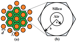
Figure 1 (a) Cross-section of hexagonal PCF, (b) Air-hole unit cell.
(1)
The cladding effective refractive index
in terms of wavelength for
and different values of
is illustrated in Figure 2.20 As can be seen in Figure 2, at a constant
cladding effective index decreases with increasing the ratio
Also, at a constant
e.i.,
by increasing wavelength, the cladding effective index will also reduce.
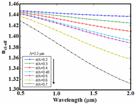
Figure 2 Cladding effective index versus wavelength at
for different values of
Determination of effective index
In order to determine the effective index of the principle mode, the following expression is used:11
(2)
The changes of the effective index in terms of wavelength at
for different values of
are shown in Figure 3. where we note that by increasing wavelength or increasing
the refractive index monotonically decreases.21 The refractive index of pure silica is obtained by Sellmeier formula as follows.21

Figure 3 Effective index versus wavelength for
and different values of
(3)
Figure 4 shows the refractive index of pure silica, along with the cladding index and effective index for
and
In this figure, it is observed that the effective index lies between the index of pure silica and cladding index. Also, with increasing
i.e., by increasing the air-hole diameter
with a constant
the difference between the refractive index of pure silica and the cladding index as well as the effective index will increase. In Figure 5(a & b), the difference between cladding index in terms of wavelength is plotted at
and
for different values of
respectively. Examining two Figure 5(a & b), it reveals that in a given wavelength, for a constant
by increasing
the difference between the effective index and cladding index will increase. For example, at the wavelength 1550 nm and for
and
the differences are 0.075 and 0.02, respectively. In Figure 6, the difference between effective index and cladding index versus wavelength is illustrated at
for different values of
With reference to Figure 6, at smaller
such as
the highest differences between two indices are obtained at smaller wavelengths. For instance, the maximum differences for
and
in the calculation range are obtained at wavelengths of 2000 nm and 900 nm, respectively.
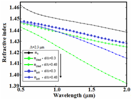
Figure 4 Variations of cladding index and effective index along with index pf pure silica versus wavelength at
for

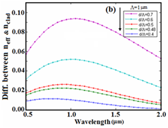
Figure 5 The difference between the effective index and cladding index versus wavelength, for different values of
(a)
and (b)
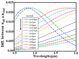
Figure 6 The difference between effective index and cladding index versus wavelength at
for different values of
Effective normalized frequency
Photonic crystal fibers are single-mode in a wide range of wavelengths. The uniqueness of the PCF depends on factors such as the
and diameter of the air-holes
.22 The effective normalized frequency
for PCF is defined as follows:23
(4)
where
and
denote the indices of silica and cladding,
represents the radius, and
is the wave number.
If the effective normalized frequency
is smaller and equal to 2.405, the condition of being single-mode is established in the PCF. The
curve in terms of the ratio
for different values of
is depicted in Figure 7, where
.23 As can be noted in Figure 7, at a given wavelength, with increasing
the value of the effective normalized frequency increases, so that at higher
the value of
may be greater than 2.405 and the PCF will act out of single mode condition. For example, at wavelength 1550 nm and
the effective values of normalized frequency for
respectively, will be equal to 1.1, 2.15, and 3.3. Also, at a constant
and
with decreasing the wavelength, the value of
will increase. For instance, in Figure 7, for
and
the value of
is 2.17, 2.4, and 2.6, respectively, where for values of
greater than 2.2, the PCF dispersion compensator fiber (PCF-DCF) will be out of single mode condition.
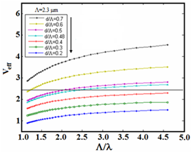
Figure 7 Variations of
versus
at
for different values of
Chromatic dispersion
The chromatic dispersion coefficient
is calculated by considering the real part of the effective refractive index
as follows:22
(5)
where
denote the velocity of light in a vacuum and
is the operating wavelength. By changing the diameter of the air-holes
and the value of
in the PCFs, the value and slope of the dispersion curve can be optimized to compensate for the dispersion in different transmission fibers in optical communication networks. In Fig. 8, the dispersion variations are plotted in terms of wavelength for different values of
The result obtained for
agrees with Ref.18 Examination of the above results shows that at a constant wavelength and
by increasing
the dispersion increases to positive values. For instance, at wavelengths 1550 nm and
the dispersions at
are -30 ps/km.nm, 28 ps/km.nm, and 55 ps/km.nm, respectively. Also, at a constant
and
, the dispersion becomes more negative as the wavelength increases.
The variations of dispersion in terms of wavelength at
for different values of
is illustrated in Fig. 9. As noted in this figure, for a constant
by increasing
would reduce the slope of the dispersion curve and becomes flattened at wider range of operating wavelengths, e.g., at
In Figure 10(a), the dispersion variations is plotted in terms of wavelength for
and different values of
Figure 10(b) shows the same curve expanded from 1
to 5
. Considering Figure 10, it can be noted that at a constant
by decreasing
negative dispersion increases to higher level. In this case, by increasing
the slope of the curve decreases and the value of wavelength increases to zero dispersion. Also, in Figure 10, we note that by placing
and
at wavelength 1550 nm, a dispersion value of -220 ps/nm.km can be achieved in PCF. Figure 11 shows the variations of dispersion in terms of
for different values of
at wavelength 1550 nm. Based on this result, in terms of required negative dispersion,
and
of dispersion compensator based on PCF can be obtained, where the highest amount of negative dispersion is achieved at
At higher values of
about 4
, the dispersions converge towards zero level.
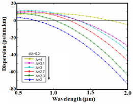
Figure 9 The variations of dispersion in terms of wavelength at
for different values of
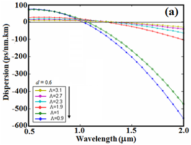
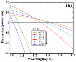
Figure 10 (a) The dispersion variations versus wavelength at
for different values of
and (b) the same curve on a larger scale.

Figure 11 The variations of dispersion in terms of
at wavelength 1550 nm for different values of
Conclusion
Since PCF has air-holes along its cladding region, then the core and cladding refractive indices cannot be determined similar to conventional optical fibers. There are several methods to determine these indices. One of these methods is fully-vectorial effective index method, which has a good accuracy for calculating dispersion in PCF. There are important parameters in PCF, such as diameter of the air-hole
and the distance between the centers of adjacent air-holes
whose variations cause the dispersion to increase or decrease under different conditions. According to the calculations performed and the results obtained, it is observed that in a PCF at a constant operating wavelength and constant
the cladding index reduces on increasing of
As a result, the effective index will reduce and the dispersion tends toward positive value. On the contrary, at a given
and a constant
on increasing operating wavelength, the effective and cladding index would decrease, then the dispersion tends towards negative values. In other words, at 1550 nm wavelength as an operating wavelength of optical communication networks, it is better to use a PCF as a dispersion compensator with a smaller
value to achieve more negative dispersion at a given
As the results show, one of the best ways to use PCF to achieve the most negative dispersion at 1550 nm wavelength is to use a PCF with
and
, where the negative dispersion is -220 ps/nm.km. On the other hand, considering constant
at the desired working wavelength, only by reduction of
we can achieve a negative dispersion. The obtained results reveal that high negative dispersion in a dispersion compensator can be achieved by a PCF with relatively a shorter length which is desired in optical communication networks.
Acknowledgments
The authors wish to acknowledge the authorities of Communication Technology Dept. of Iran Telecom Research Center for the permission to publish the present article for P.A. No. 440950900.
Conflicts of interest
The author declares there is no conflict of interest.
Funding
References
- Rajiv Ramaswami. Optical Fiber Communication: From Transmission to Networking. IEEE Commun Mag., 50th Anniversary Commemorative Issue, 2002.
- Lars Grüner-Nielsen, Marie Wandel, Poul Kristensen, et al. Dispersion compensating fibers. IEEE J Lightwave Technol. 2005;23(11):3566.
- RL Sharma, Ranjit Singh. Dispersion Compensation in Single Mode Fibers for High Speed Systems. VSRD Int J Elect Electron & Comm Eng. 2011;1(4):210–219.
- Roger L Freeman. Fiber-Optic Systems for Telecommunications, Wiley Interscience, Canada, 2002.
- Faramarz E Seraji, Jamshid Ahvati. Design of Dispersion Compensating Fibers with High Negative Dispersion and Low Bending Loss: A Comparative Analysis. Int J Opt App. 2014;4(2):40–45.
- Faramarz E Seraji, Razieh Kiaee. A Revisit of Refractive Index Profiles Design for Reduction of Positive Dispersion, Splice Loss, and Enhancement of Negative Dispersion in Optical Transmission Lines. Int J Opt App. 2014;4(2):62–67.
- TA Birks, D Mogilevtsev, JC Knight, et al. The Analogy Between Photonic Crystal Fibers and Step Index Fibers. In Proc OFC/IOOC. 1999;114–116.
- Faramarz E Seraji, Vajieh Arsang. Analytical comparison of photonic crystal fibers for dispersion compensation with different structures using FDTD method. Phy & Astron Int J. 2018;2(2):155–158.
- TA Birks, JC Knight, PSt J Russell. Endlessly single-mode photonic crystal fiber. Opt Lett. 1997; 22(13):961–963.
- Yanfeng Li, Yuhong Yao, Minglie Hu, et al. Improved fully vectorial effective index method for photonic crystal fibers: evaluation and enhancement. Appl Opt. 2007;47(3):399.
- RK Sinha, SK Varshney. Dispersion properties of photonic crystal fibers. Microwave Opt Technol Lett. 2003;37:129–132.
- RK Sinha, AD Varshney. Dispersion Properties of Photonic Crystal Fiber: Comparison by Scalar and Fully Vectorial Effective Index Methods. Opt Quant Electron. 2005;37:711–722.
- Jui-Ming Hsu, Wen-Hao Zheng, Cheng-Ling Lee, et al. Theoretical investigation of a dispersion compensating photonic crystal fiber with ultra-high dispersion coefficient and extremely low confinement loss. Photon Nanostructures: Funda App. 2016;16:1–8.
- Russel Reza Mahmud, SM Abdur Razzak, Md Imran Hasan, et al. Ultraflattened high negative chromatic dispersion over O+E+S+C+L+U bands of a microstructured optical fiber. Opt Eng. 2015;54(9):097105(1–7).
- Shovasis Kumar Biswas, Rishad Arfin, Ashfia Binte Habib, et al. A Modified Design of a Hexagonal Circular Photonic Crystal Fiber with Large Negative Dispersion Properties and Ultrahigh Birefringence for Optical Broadband Communication. Photonics. 2019;6(19):1–14.
- G Prabhakar, A Peer, A Kumar, et al. Finite element analysis of solid-core photonic crystal fiber. 2012 Students Conf. Eng. Syst., Allahabad, Uttar Pradesh, 2012;1–5.
- Z Zhu, TG Brown. Analysis of the Space Filling Modes of Photonic Crystal Fibers. Opt Exp. 2001;8(10):547–554.
- Lin-Ping Shen, Wei-Ping Huang, Shui-Sheng Jian. Design of Photonic Crystal Fibers for Dispersion-Related Applications. IEEE J Lightwate Technol. 2003;21(7):1644.
- FE Seraji, M Rashidi, V Khasheie. Parameter Analysis of a Photonic Crystal Fiber with Raised Core Index Profile Based on Effective Index Method. Chin Opt Lett. 2006;4|(8):442.
- Yanfeng Li, Yuhong Yao, Minglie Hu, et al. Improved fully vectorial effective index method for photonic crystal fibers: evaluation and enhancement. Appl Opt. 2007;47(3):399.
- Ajoy Ghatak and K.Thyagarajan, Introduction to Fiber Optics, Cambridge Univ. Press, 2002.
- Frédéric Zolla, Gilles Renversez, André Nicolet. Foundations of Photonic Crystal Fibres, Imperial College Press, London, 2005.
- Shailendra K, Varshney MP, Singh PK. Propagation Characteristics of Photonic Crystal Fibers. J Opt Commun. 2003;24:192–198.

©2020 Seraji, et al. This is an open access article distributed under the terms of the,
which
permits unrestricted use, distribution, and build upon your work non-commercially.


