Open Access Journal of
eISSN: 2575-9086


Research Article Volume 2 Issue 2
Bnadung Institute of Technology, Indonesia
Correspondence: Apit Nurmalasari, Bnadung Institute of Technology, JI, Rambay no. 68 kel, Sukamanah kec, Cisaat kab, Sukabumi, Indonesia, Tel +62 83826292591
Received: March 03, 2018 | Published: April 30, 2018
Citation: Nurmalasari A. Exploration of epithermal gold deposit using induced polarization method in banyumas, Indonesia. Open Access J Sci. 2018;2(2):154-161. DOI: 10.15406/oajs.2018.02.00063
Area TG was spotted as gold mineralization zone in Banyumas, Indonesia. Gold deposit was created by hydrothermal activity. It shaped as vein or dissemination of rock. One of geophysics method which suitable for metal mineral exploration is induced polarization method. It used characteristic of polarization in medium when current was injected. Induced polarization was measured by double dipole configuration as long as 2x1 kilometers. Space between lines is 100 meters and space between electrodes is 50 meters. Materials and tools that used were liquid CuSO4, NaCl, 1 set Transmitter Phoenix model IPT1, 1 unit Receiver Phoenix model IPV1, 4 rolls of cables, 2 porous pot, 2 metal electrode, 1 unit power set with maximum output frequency 50 Hz, 2 units handy talky, 1 unit Laptop, software Microsoft excel 2007, software Surfer 9.0, and software Res2Dinv. We have chosen 2 lines TG.000 and TG.-200 that interest zone representing outcrops and induction polarization anomaly.
Keywords: induced polarization, gold deposit, anomaly, resistivity, double dipole configuration
IP, induced polarization; MF, metal factor; PFE, percent frequency effect
Gold deposit was created by hydrothermal activity. It has shaped as vein or dissemination in rock.1 Gold was associated with another mineral such as silver, copper, mercury or other element that affect by their circumstance.2 one of geophysics method which can detect it is geoelectric especially induced polarization (IP). The method used to get subsurface information based on characteristic of their electricity. It was using characteristic polarization of medium when current was injected.3,4 There are two things that affect polarization of rock, are electrode polarization and membrane polarization. An illustration of induction polarization can be described by four sets standard electrode. When current was injected and stopped, potential was not drop to null drastically but slower. Voltage dropped slowly that measured in time function and known as induction polarization time domain. If current was flowing again, potential will back to initial amplitude in almost same time interval. It is clear that apparent resistivity (complex impedance) was varied by frequency. Apparent resistivity was measured in two different frequencies below 10 Hz, known as induction polarization frequency domain. Area TG was spotted as gold mineralization zone in Banyumas, Indonesia. In common, alteration zone was created by hydrothermal activity will be followed by quartz vein.1 We hope that investigation by induced polarization method can give dissemination map from alteration rock as indicated gold mineralization. Gold mineralization zone will give high PFE and resistivity which very high or low as induced polarization anomaly.
Parameters that we measured in induction polarization frequency domain are apparent resistivity, percent frequency effect (PFE), and metal factor (MF). Apparent resistivity can defined as
(2.1)
With is apparent resistivity (Wm), K is geometry factor of electrode configuration, is different potential (mV), a is space between electrode, and I is current (mA). Figure 1 shows the simplest series which suitable with induction polarization effect. Warburg impedance described as , with is a constant and as reactive capacitive. If defined as then,5
(2.2)
(2.3)
(2.4)
as
then
(2.5)
We substitute eq. (2.5), then eq. (2.1) can be written as:
(2.6)
Frequency effect was measured by two different frequencies (low frequency and high frequency), defined as3,4
(2.7)
In percentage (%), FE can be written,4
(2.8)
With is percent frequency effect (%), is apparent resistivity that measured when low frequency (0,05-0,5 Hz), and is apparent resistivity that measured when higher frequency (1-10 Hz). Value PFE is a response from mineral existence which content by pores of rock. Higher mineral concentration, higher value PFE. Based PFE definition, metal factor (MF) can defined as how much base mineral in rock content. Value MF or metal conduction factor defined as3,4
(2.9)
With 2px105 is arbitrary factor so value in an acceptable ordo. Value metal factor have unit mhos per meter (siemens per meter).
Induction Polarization was measured in interest area 2x1 kilometers. It was classifying have a huge large then we used 50 m as space between electrode and 100 m as space between line to get detail information both vertically and horizontally. We used double dipole configuration to reduce noise such as capacitive coupling.6 It can reduce a really long cable for measurement. Design of line and measurement shown respectively in Figure 2 & Figure 3. As for material and tools, we used liquid CuSO4, NaCl, 1 unit Transmitter Phoenix model IPT1, 1 unit Receiver Phoenix model IPV1, 4 rolls of cables, 2 porous pot, 2 metal electrode, 1 unit power set with maximum output frequency 50 Hz, 2 units handy talky, 1 unit Laptop, software Microsoft excel 2007, software Surfer 9.0, and software Res2Dinv. All tools with its specification which has been used have shown in Appendix A. We get different potential used to calculating apparent resistivity, PFE, and MF.Then, we model each parameter by Surfer 9.0 and inverse it by Res 2Dinv. Measurement value will be interpreted by supporting magnetic response and area geology. Magnetic response has been shown in Appendix B and geology of its area also has been shown in Appendix C. We have to calibrate the equipment before use. This can do by connecting sub out terminals of transmitter to input of receiver used two cables. Then, we were connecting output from transmitter to dummy resistor. Current was about 0.5 ampere and was set switch voltage selector in section power at 100 volts. The equipment will be calibrated if input of receiver (voltage) has same amount with current from transmitter (ampere) multiple by resistance 0.1 Ohm. Calibration setting has been shown in Figure 4. The measurement was done by injecting current to the earth. We set the current in transmitter section. Principle of how transmitter works as follows. First, we turned on generator. Then, we push button ‘On’ at power section and put transformer stepdown to decreased voltage from 220 volts to 110 volts. Ground was connecting to the soil to remove electrical current effect. Then, we put jumper cable from power supply to input controller induction polarization and electrode cable to output section of controller induction polarization.
Voltage was setting about 300 volts. We have to check contact connection of electrode with soil. Contact resistance should be less from 5 kilo Ohm (kW). Current was injected by push button ‘operate’. Maximum current was 1,000 miliampere (mA). Current was setting until maximum selector voltage as 300 volts. Then, we set frequency at 0.3 hertz (Hz). If reading of receiver was complete, frequency have to change at 3 hertz. Current was stopped by push button ‘stand by’ and turning ‘multiplier’ to nullified the current. How receiver work will describe as follows. We turned on the tool by push button ‘on’ at battery. The next step is checking contact of porouspot with soil. Resistance of porouspot should be less than 2 kiloohms. If resistance of porouspot more than 2 kiloohms, we should have added liquid CuSO4. Porouspot cable was connected to input. The part of connection should wrap completely. Then, we set appropriate current range and read voltage at ‘level’. We push button ‘fine’ and nullified the voltage. Frequency was setting at 0.3 hertz to get value of percent frequency effect (PFE). After that, we were setting frequency at 3 hertz and voltage was nullified. All data that we get was processed by import it to Microsoft excel 2007. Set data of a dan n was used to calculate geometry factor K as equation (2.26). Value of geometry factor K that we get, current I that we injected, and potential difference will be used to calculate apparent resistivity values as equation (2.25). All value of apparent resistivity , apparent percent frequency effect, apparent metal frequency, elevation and position will be grid by methods Kriging in surfer 9.0 to create pseudosection of apparent resistivity , apparent percent frequency effect and apparent metal frequency. Value of percent frequency effect which calculated, we use for calculate metal factor in rocks by equation (2.33). Data of topography, spaces, n, resistivity values, and percent frequency effect or metal factor was saved in file text (extension*.txt) in notepad. Then, apparent resistivity , apparent percent frequency effect, and apparent metal frequency, was inverted by methods least square at software Re s2Dinv. Output of inverted values was saved in surfer plot. Values of apparent resistivity , apparent percent frequency effect, and apparent metal frequency, elevation and position was gridding by methods kriging to create transversal profile two dimension of apparent resistivity , apparent percent frequency effect, and apparent metal frequency. We had done the same thing to output of inverted value by Res2Dinv. We also make a transversal profile two dimension of true resistivity , true percent frequency effect, and true metal frequency. Both profile was interpreted with help of geology area and map of magnetic intensity.
For representation, we have chosen two lines are TG.000 and TG.-200 that where outcrops has been found and induction polarization anomaly respectively. Pseudosection of apparent resistivity in Figure 5(A) at n=3 to n=6 point 200to400 shows high resistivity as sandstone response (>30Wm). Range of resistivity value has been shown in Appendix D. At point 300, magnetic profile show kick of low magnetic which followed by high resistivity at n=6. Pseudosection of PFE shows low value between 2-3% at n=3 to n=6, but at point 300 it shows moderate value as 3.2%. At n=3 to n=6, pseudosection of MF shows low metal content (<100 S/m) as clays. Magnetic profile shows smooth pattern in line TG.000 at point 150 to 450 that altered sandstone. Pseudo section of inversion result in Figure 5(B) shows that rock was conductive. Point-500 to-700 at n=1 to n=2 have high resistivity (>30 Wm) as clays response. It also shows high resistivity lineal shaped at point-750 to -650 with n=1 to n= 6, which indicated an intrusion. Pseudosection of PFE shows high value in point -650 to -550 at n=1 to n = 2 and point -850 to-250 at n=4 to n=5. A significant magnetic profile shows at point -650 to–500 indicated non-altered breccia andesite. Interest zone at TG.000 is not shown indication of mineralization. PFE value is low and characteristic of sandstone that can’t be a gold deposit. Pseudosection of apparent resistivity shows lineal shaped high resistivity in point 450 to–500 Figure 6(A). High resistivity (>30Wm) also shows in point -450 to -500 at n=1 to n=6 and point -600 to -800 at n=1 to n=3. Pseudosection of PFE shows moderate value in point -650 to -700 at n=1 to n=6 as indicated as orthogonal intrusion. Metal content is low at n=1 to n=4 as clays and is high at n=5 to n=6 as sandstone enriched with sulfide.

Figure 5 (A) Pseudosection of apparent resistivity, PFE, and MF; (B) Pseudosection of true resistivity, PFE, and MFat line TG.000.
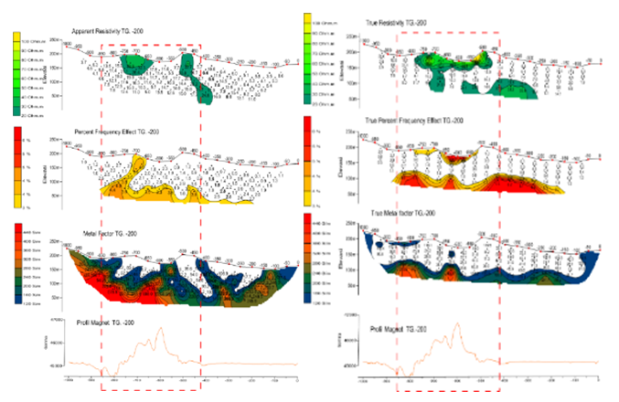
Figure 6 (A) Pseudosection of apparent resistivity, PFE, and MF; (B) Pseudosection of true resistivity, PFE, and MFat line TG.-200.
Figure 6(B) shows inversion result and high value for pseudosection of true resistivity about 33,6 Wm-95,2 Wm at n = 3 to n = point 150 to 450 that indicated sandstone. At point 300, there is a low kick magnetic which indicated as altered sandstone. Pseudosection of true PFE shows moderate value to high at n=3 to n=5 about 3-6,5 %. Pseudosection of true MF show high value (>200 S/m) at n=5 in interest zone. Line TG. -200 at point -450 to-850 show a significant magnetic fluctuation. Magnetic profile shows at point - 850 to -750 a very low gamma as altered breccia andesite, but at point -750 to 450 a very high gamma as fresh or non-altered breccia andesite. Point -1000 to -850 and point -400 to 0 shows smooth magnetic profile as silt sandstone.7 Anomaly of induce polarization at interest zone line TG.-200 shows high resistivity and high value of PFE at point -450 to -800. Mineralization can be found if there are a lineal shaped intrusion and pyrite dissemination, but it does not indicate quartz mineral which have high resistivity. It also does not fit altered vein epithermal model (see Appendix E). This means that mineralization does not associated with gold mineral, but others. In another word, in Banyumas did not found gold deposit. Rock resistivity was affected by conductivities of fluid which content pore of rocks, mineral as composition of rocks, and structure pore of rocks. Range value of resistivity can be used as a clue to what minerals that make rock composition. The mineral that compose a rock have tendency to be associate with gold mineral (element Au). Vein of mineralization has been interpreted through profile of resistivity, percent perfect effect and metal factor at each line which supported by geology map of interest area, position of geophysics measurement and thematic of magnetic intensity map (TMI map, Appendix D).
Lithology of line of TG.000 from point -1000 to point 1000 are sandstone as mix of silt-clay-sand. Clay content of sandstone can create phenomenon of induction polarization that happen because membrane polarization. However, clay minerals are not one of clue of epithermal gold deposit low sulfidation. Line TG.000 have low magnetic (44941 Gamma) as thematic of magnetic intensity map. Lithology of line of TG.-200 from point -1000 to point 0 are sandstone with mix of andesite-breccia at point -800 to point -750. Andesite that have content minerals hornblende and pyrite dissemination 1-3% is one of indication epithermal gold deposit low sulfidation (minerals adularia-sericite). This type of andesite is a mineralization agent. We predict that point -800 to point -600 are fault structure as thematic of magnetic intensity map and position of measurement has shown. Mostly mineralization follow crack in rock or structure of fault. Induction polarization anomaly of interest zone at line TG.-200 which predicts as breccia-andesite has shown high resistivity value of rock and also high percent frequency effect response at point -450 to point -800. With pyrite dissemination 1-3% and intrusion as rip open can be indicated as tendency that mineralization to happen. However, resistivity value as we get didn’t show minerals quartz that have range about 2x10⁴ Wm-2x10⁶ Wm. As shown at Appendix B as alteration of vein epithermal model, intrusion zone as mineralization deposit did not show appropriate trend with model. This indicate mineralization that happen did not associated with minerals gold as we wish, but another. It looks mineralization at rock breccia-andesite associated with other mineral as base metal. On other words, epithermal gold deposit did not found in village TG Regency Banyumas, Indonesia.8,9
Line TG.000 is where outcrops have been found. It shows induction polarization anomaly but did not lead to mineralization. For interest zone line TG.-200 show high value PFE and indication of lineal shaped intrusion which can lead to mineralization. At point -1000 to 0 is sandstone which implied by breccia andesite at point 850 to -750. Unfortunately, that mineralization did not associated with gold mineral, but others.
The author thanks to Mr. Satriya Alrizki and Mr. Sugito. This work was supported by Aneka Tambang Corp.
The author declares there is no conflict of interest.
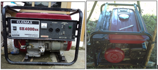
Figure 1 Generator Elemax SH400 DX: (left) front show; (right) upper show.
Figure and Specification of Equipment
Generator Elemax SH4000 DX
We used generator that used gasoline as source of current plant. This generator has specification as follows. For alternating current (AC), it have voltage about 220 volts, frequency 50 hertz, average output 2,7 kVA, maximum output 3,7 kVA, and phase 1f. We have voltage about 12 volts and current 8.3 ampere for direct current (DC).
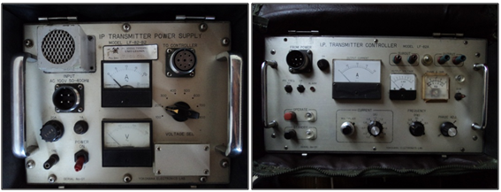
Figure 2 A transmitters from front side: (left) Induction polarization power supply; (right) Induction polarization controller.
Transmitter Yokohama model LF-82A
Transmitter consist of two parts are power supply and controller section. It has specification as follows. Primer input voltage from current generator is about 90 VAC-130 VAC, 50 hertz, 60 hertz, and 400 hertz. Maximum output voltage about 800 volts and its minimum 40 volts. Output current has maximum about 2 amperes and its minimum 40 volts. Transmitter create square wave of frequency about 3 hertz, 0.3 hertz, 1 hertz, and 0.1 hertz. There is a safety series for voltage or current overload. Resistance resistor is about 4,000 to 100 ohm.
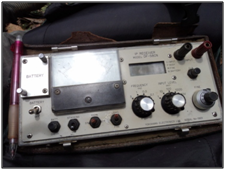
Figure 3 A receiver show at front side.
Receiver Yokohama model DF-58CN
This section only consists of one part. Mostly, receivers have specification as follow. It has few sensitivity values are about 1 millivolt, 10 millivolts, 100 millivolts, 1,000 millivolts, and 10 volts. The receiver has input impedance about 2 million ohms. It has resolution about 0.1%-1% from sensitivity LCD monitor, 0.1% in frequency effect in meter. Receiver has some disturbance. First, it has disturbance in input voltage about ±5% for 1 milivolt to 10 volts. It also have disturbance in frequency effect about±0.5% for 1 milivolt to 10 volts. The receiver has resistance resistor from 0.1 KW to 10 KW. Range can be set as± 5% , ±15% and±100%. It has size about (240x110x220) mm3 as weight about 3.5 kilograms. We used three batteries or a Ni-Cd battery as voltage source. There are four frequencies that can be switch 0.1 Hz, 0.3 Hz, 1 Hz, and 3 Hz.
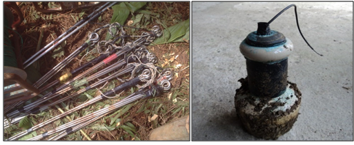
Figure 4 Electrodes: (left) bar electrodes; (right) electrode porouspot.
Electrodes
Electrodes is a device that connecting transmitter or receiver directly to the earth. There are two kinds of electrodes which used in this experiment, electrodes bar and porouspot. Particles of mineral base metal at electrode bar which have a contact with liquid of rock pores will get different potential to its liquid even if there are no current at all. This makes different relative activities which that amount depends on its relative activities. This kind of potential difference called as electrode potential. If we have injected current to system of mineral base metals, then will happen current polarization at upper border side between mineral base metal and its liquid. This phenomenon called as electrode polarization. We used bar electrode in salt liquid such as base metal Cu in liquid CuSO4 to avoid electrode polarization. A stainless metal will benefit in field operational because it has light weight. Quick and easy in use. Electrode porouspot is an electrode non-polarization. Their potential value did not affect by current that have through, but depend on potential their medium. Electrode porouspot consist of copper bar which immersed in liquid CuSO4 and packaged used porcelain materials that porous at beneath path so liquid can permeate slowly and have contact with soil.
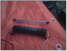
Figure A5 Dummy resistor.
Dummy resistor
We used dummy resistor to calibrate both transmitter and receiver of induction polarization methods. The dummy resistor has been shown at figure as follow.
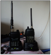
Figure E6 Handy talky.
HT(Handy talky)
We used handy talky for communicate one to another when take a measurement. This is needed because experiment area is big and have broad areal. We take space electrode about 50 meters. The handy talky has been shown at figure as follow.
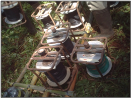
Figure A7 Cables Roll.
Cables Roll
We need cables roll to connected any equipment because experiment area is such big enough. Cable also connected electrode with the earth so current can be well injected. We can see some cables roll that we used as follow.
Figure 8 Liquid CuSO4 in a bottle.
Liquid CuSO4
Larutan CuSO4 sebagai cairan pengisi elektroda porous pot agar mendapatkan kontak yang baik dengan bumi. Liquid CuSO4 is a content of electrode porouspot. This kind of electrode used so we can avoid electrode polarization and better contact with the earth.
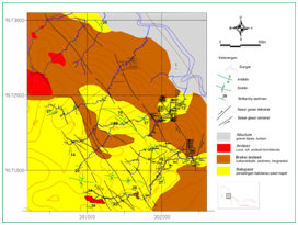
Figure C Geology map of Village TG.
Geology Profile of measurement Area
Genealogy of gold deposit
In general, gold creation has related with increased magma and its residue that we called as hydrothermal liquid. Hydrothermal process was formulated as a change in rock that affect by a rising hot water to the surface. Accumulation of mineral sulfides from hydrothermal process that generally happen at open spaces as known as trap structure such as fault and cracked structure. Place of mineral sediment by hydrothermal process can be divided by epithermal sediment, mesothermal sediment and hypothermal sediment. The condition of hydrothermal sediment can be created as follow. First, there is a liquid source agent of element minerals. Second, it should there is a crack or pore that can be through by hydrothermal liquid. Third, there a place to precipitation of hydrothermal liquid. Next, there is a chemical reaction to lead hydrothermal sediment. Lastly, an enough concentration from element that created mineral sulfides and hydrothermal liquid.
Geology profile of TG
Morphology
Morphology of measurement area is mixing of hill with elevation about 70 to 150 meters from sea surface and its slope about 20-30 degrees. The area arises by pine trees. Village TG more affected by structure of layering sediment between silt-sandstone and breccia-andesite.
Lithology
Mostly, lithology of Village TG is mix between sandstone-silt and breccia-andesite with layering at 160 degrees at north side to 190 degrees at east side. Breccia andesite is a graduation from volcanic breccia andesite clastic to sediment. At under part, it looks andesite more dominantly as a layering creation with slope to east-south side. This layering have non-distinct border. It has interpreted as clastic volcanic-pyroclastic rocks that have phase transition to be turbidity-sandstone. Turbidity-sandstone is sediment that has precipitate by turbidity current mechanism. Turbidity current has higher viscosity than hydrothermal liquid (Keunen and Migliorini, 1950). For silt-sandstone is a mix between slit, sandstone and clay with material substance such as clays, feldspar, fossil, and few fragment of rocks. At some point, it has been silicification and there is pyrite dissemination 1% with spread of dense non-rule vein calcite. It is shown that silt has been silicification and more brittle than sandstone. For andesite layer as lava and sill with mineral mafic such as hornblende. Andesite layer has been predicting as volcanism product of Pleistocene era and as part of volcanic arrangement Mandirancan and Kebasen (East River Serayu). This layer has not been alteration and interpreted as part of mineralization agent.
Geology structure
Geology structure that had been created as fault at south-east side to north-west also at some point mineralization spot. This fault is part of translation fault Southeast-Northwest with fault motion North 300° to 330° East. It has been cut fault Southwest-Northeast and fault East to West. Those fault has been created drag-fold because intensive motion at some place so it is hard to know where prime anticline. Mineralization have high tendency to associate with those faults.
Alteration and mineralization
Area Village TG has been indicated as spot that epithermal gold mineralization happen by two clues mineral silica-pyrite (ore silicification) and vein calcite-quartz at rock of sediment. Mineralization process as follow as major fault North 300°to 330° East with orthogonal dip until 60 degree. Mostly, host rock of mineralization is sandstone-silt with alteration vein as long as structure. In the same line, will be shown grow from dense crack zone, vein stock work-calcite and selective silicification at silt layer. All sulfide dissemination as pyrite at this zone did not followed by hydrothermal alteration. Silicification at silt-sandstone has associated vein with rich calcite. We did not detect gold content at moderate to high silicification zone (<0,02 part per million Au), but it does detect at low to moderate silicification zone. There is gold content about 0.18 to 0.48 part per million. We do some chemical analyze of rock from 34 samples at second semester at year 2009. It includes sample calcite, sandstone and high silisification zone. All sample show content average mineral gold about 0.1 to 0.5 part per million Au. Silicified silt-sandstone have shown 0.1 to 0.18 part per million Au and silica-pyrite has shown about 0.15 part per million Au. We get high gold content at vein calcite-clays about 0.35 to 0.48 part per million Au. This indicate that mineralization have high tendency to associate with vein calcite. Alteration of this zone is hard to see, but it is a mix between calcite-quartz and some minor sericite. Geology map of Village TG has been shown at figure as follow.
Table of resistivity value and metal factor of minerals
Minerals |
Formula |
|
Resistivity (Wm) |
Average |
Bismuthinise |
Bi2S3 |
18-570 |
||
Covellite |
CuS |
3x10⁻⁷-8x10⁻⁵ |
2x10⁻⁵ |
|
Chalcocite |
Cu2S |
3x10⁻⁵-0.6 |
10-4 |
|
Chalcopyrite |
CuFeS2 |
1.2x10⁻⁵-0.3 |
4x10⁻³ |
|
Bornite |
Cu2FeS4 |
2.5x10⁻⁵-0.5 |
3x10⁻⁴ |
|
Pyrite |
FeS2 |
2.9x10⁻⁵-1.5 |
3x10⁻¹ |
|
Pyrrhotite |
FenSm |
6.5x10⁻⁶-5x10⁻² |
10-4 |
|
Cinnabar |
HgS |
2x10⁻⁷ |
||
Molybdenite |
MoS2 |
10-3-10-6 |
10 |
|
Galena |
PbS |
3x10⁻⁵- 3x10⁻² |
2x10⁻³ |
|
Millerite |
NiS |
3x10⁻⁷ |
||
Stannite |
Cu2FeSnS2 |
10-3-6x10³ |
||
Stibnite |
Sb2S3 |
105-1012 |
5x10⁶ |
|
Sphalerite |
ZnS |
1.5-107 |
102 |
|
Cobaltite |
CoAsS |
3.5x10⁻⁴-10-1 |
||
Arsenopyrite |
FeAsS |
2x10⁻⁵-15 |
3-4 |
|
Niccolite |
NiAs |
10-7-2x10⁻³ |
2x10⁻⁵ |
|
Bauxite |
Al2O3.nH2O |
2x10²-6x10³ |
||
Cuprite |
Cu2O |
103-300 |
30 |
|
Chromite |
FeCr2O4 |
1-106 |
||
Specularite |
Fe2O3 |
6x10⁻³ |
||
Hematite |
Fe2O3 |
3.5x10⁻³-107 |
||
Limonite |
2Fe2O3.3H2O |
103-107 |
||
Magnetite |
Fe3O4 |
5x10⁵-5.7x10³ |
||
Ilmenite |
FeTiO3 |
10_15 |
||
Wolframite |
Fe,Mn,WO4 |
10-105 |
||
Pyrolusite Quartz |
MnO2 |
5x10⁻³-10 |
||
Cassiterite |
SiO2 |
4x10¹⁰-2x10¹⁴ |
||
Rutile |
SnO2 |
4x10⁻⁴-104 |
0.2 |
|
Uraninite |
TiO2 |
30-1000 |
500 |
|
Anhydrite |
UO2 |
1-200 |
||
Calcite Fluorite |
CaSO4 |
109 |
||
Siderite |
CaCO3 |
2x10¹² |
||
Rocksalt |
CaF2 |
8x10¹³ |
||
Sylvite |
Fe2(CO3)3 |
70 |
||
Diamond |
NaCl |
30-1013 |
||
Serphentine |
KCl |
1011-1012 |
||
Hornblende |
C |
10-1014 |
||
Mica |
|
2x10²-3x10³ |
||
Biotite |
2x10²-106 |
|||
Bitum coal |
9x10³-1014 |
|||
Anthracite |
2x10²-106 |
|||
Lignite |
0.6-105 |
|||
Fire clay Meteoric |
10-3-2x10³ |
|||
waters Surface |
9-200 |
|||
waters (Igneous |
30 |
|||
rock) Surface |
30-103 |
|||
waters (Sediment) Soil waters |
0.1-3x10³ |
|||
Natural waters (Igneous rock) |
10-100 |
|||
Natural water |
100 |
|||
(Sediment)Sea water |
0.5-150 |
9 |
||
Saline waters, 3% Saline water, 20% |
1-100 |
30.2 |
||
0.15 |
||||
Table 1 Resistivity of minerals
|
Rock type |
Resistivity range (Wm) |
|
Granite porphyry Feldspar porphyry Syenite Diorite porphyry Porphyryte Carbonatized porphyry Quartz diorite Porphyry (various) Dacite Andesite Diabase (various) Lavas Gabbro Basalt Olivine norite Peridotite Hornsfels Schists (calcareous and mica) Tuffs Graphite schist Slates (various) Gneiss (various) Marble Skarn Quartzites (various) Consolidated shales Argilites Conglomerats Sandstone Limestone Dolomite Unconsolidate wet clay Marls Clays Oil sands |
4.5x10³ (wet)-1.3x10⁶ (dry) 4x10³ (wet) 102-106 1.9x10³ (wet)-2.8x10⁴ (dry) 10-5x10⁴ (wet)-3.3x10³ (dry) 2.5x10³ (wet)-6x10⁴ (dry) 2x10⁴-2x10⁶ (wet)-1.8x10³ (dry) 60-104 2x10⁴ (wet) 4.5x10⁴ (wet)-1.7x10² (dry) 20-5x10⁷(dry) 102-5x10⁴ 103-106 10-13x107 (dry) 103-6x10⁴ (wet) 3x10³ (wet)-6.5x10³ (dry) 8x10³ (wet)-6x10⁷ (dry) 20-104 2x10³ (wet)-105 (dry) 10-102 6x10²-4x10⁷ 6.8x10⁴ (wet)-3x10⁶ (dry) 102-2.5x10⁵ (dry) 2.5x10² (wet)-2.5x10⁴ (dry) 10-2x10⁵ 20-2x10³ 10-8x10² 2x10³-104 1-6.4x10⁵ 50-107 3.5x10²-5x10³ 20 3-70 1-100 4-800 |
Table 1 Study animal information: ID, gender, age, and dates of data collection for each study animal
Material |
Metal Factor (mhos/cm) |
|
Massive Sulfides |
10,000 |
|
Fracture-filling sulfides |
1,000-10,000 |
|
Massive magnetite |
3-3,000 |
|
Porphyry copper |
30-1,500 |
|
Dissem. Sulfides |
100-1,000 |
|
Shale-sulfides |
3-300 |
|
Clays |
1-300 |
|
Sandstone 1-2 % sulfides |
2-200 |
|
Finely Dissem. Sulfides |
10-100 |
|
Tuffs |
1-100 |
|
Graphitic sandstone and limestone |
Apr-60 |
|
Gravels |
0-200 |
|
Alluvium |
0-200 |
|
Precambrian gneisses |
10-100 |
|
Granities, Monzonites, diorites |
0-60 |
|
Various volcanics |
0-80 |
|
Schists |
Oct-60 |
|
Basic rocks (barren) |
10-Jan |
|
Granites (barren) |
1 |
|
Groundwater |
0 |
Table 3 Metal factor of rock

Figure 1 Cross section simulation scheme of (a) gold deposit epithermal low sulfidation, (b) resistivity for any alteration.9

©2018 Nurmalasari. This is an open access article distributed under the terms of the, which permits unrestricted use, distribution, and build upon your work non-commercially.