eISSN: 2574-9927


Research Article Volume 2 Issue 4
1Tsinghua University, Beijing, China
2Key Laboratory for Advanced Materials Processing Technology, Ministry of Education, China
Correspondence: Kang J, Key Laboratory for Advanced Materials Processing Technology, Ministry of Education, China
Received: June 15, 2018 | Published: July 13, 2018
Citation: Wang S, Kang J, Zhang X, et al. The effect of ultrasonic treatment on the microstructure of Sn–58Bi alloy. Material Sci & Eng. 2018;2(4):96-99. DOI: 10.15406/mseij.2018.02.00041
Ultrasonic treatment of the melt metals is a hot research topic. In this paper, ultrasound was introduced from the bottom into liquid metal. By this way, the ultrasonic treatment can be acted on the liquid metal from pouring to the end of solidification. The effect of ultrasonic treatment on the microstructure of Sn–58wt.%Bi alloy are studied with the variation of different power levels. The microstructure of the treated specimen is significantly refined and only granular bismuth and tin phases is obtained, compared to the coarse dendrites microstructure without ultrasonic treatment. What’s more, the refining mechanism of the microstructure is discussed. The coarse Bi phases are broken into fragments by cavitation bubbles during ultrasonic treatment and they move along with the acoustic stream and then serve as new nucleus for solidification. This process could last to the end of solidification.
Keywords: ultrasonic treatment, Sn–58BiAlloy, grain refinement, divorced eutectic phases, cavitation bubble
Ultrasonic treatment (UST) has been extensively used in the refining and degassing of melt alloys by using the nonlinear effects such as cavitation and acoustic streaming caused by ultrasound.1–5The common benefits of applying ultrasound include (1) significantly refining microstructure,6–17 thereby, improving mechanical properties such as tensile strength,16–19 (2) environmental friendly features by replacing the using of refining agents.20–22 However, ultrasonic treatment of the melt has some deficiencies such as contact with the melt and limitation of processing time.23 The contact of ultrasonic probe with the melt requires special materials for the probe to endure high temperature and corrosion.23 What’s more, as the ultrasonic treatment is before or during the solidification process, which means the treatment process cannot last too long. If it is late to take the ultrasonic probe out, the probe will be welded with the solidified specimen. Efforts had been made to study the UST effect in different temperature range.9 An innovative method was proposed using upward ultrasonic treatment by Kang.24,25 The main advantage of this method is that the ultrasonic treatment can be active through the whole solidification process. In this way, ultrasound probe is pointing upwards and the metal to be treated is weld or cast together with the probe of the same diameter. In this paper, ultrasound was introduced upward as that in24 and25 for the treatment of Sn–58wt.%Bi. The effects of cavitation on its microstructure were investigated.
A schematic diagram of ultrasound device used in this experiment is shown in Figure 1. The ultrasound device contains an ultrasound generator and an output terminal with 20 kHz frequency and continuously adjustable power in the range of 0–600W. The probe, 26mm in diameter, was pointing upward and a quartz tube of 28mm in inner diameter and100mm long was slipped on the top of the probe. Bentonite was used to seal the gap between the probe side surface and the tube. Meanwhile, the seal can avoid the direct contact of the tube and probe, which is helpful for the prevention possible breaking of the tube during ultrasonic treatment. Sn–58wt.%Bi was melt at 250 °C and held for 30min and then poured into the quartz tube. Ultrasonic sound was introduced from pouring to the end of solidification. However, the immersion way of the probe into the melt from the top could not last the whole solidification process because of the prevention of the welding of the sample and probe. The power of ultrasonic sound was set as 100W and 150W.
Effects of ultrasound treatment on macrostructure
Figure 2a shows the macrostructure of samples under different power of Ultrasound treatment. Typical dendrites were seen without ultrasound treatment, while no dendrites were clearly found with ultrasound treatment, but more air holes appeared instead. These air holes distribute mostly around the corner and exit as clusters. A big hole was seen on the sample when the ultrasound power is 150W. The high content of air was mainly caused by the ultrasound treatment spanning the whole process from pouring to solidification. Many studies show that ultrasound treatment increases air content due to the poor fluidity when the solid fraction is big during solidification,26 but the existing bubble could be helpful to investigate its interaction with solidification part. In addition, some stripy structures were found from Figure 2b & Figure 2c, there are not scratches during polishing.

Figure 2 Macrostructure of Sn-58%Bi alloy under different ultrasound treatment (a) 0W; (b) 100W; (c) 150W.
Effects of ultrasound treatment on microstructure
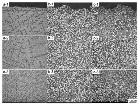
The microstructures of the bottom, middle, and top of Sn–58wt.%Bi specimen under different power of ultrasound treatment are illustrated in Figure 3. The microstructure of the sample without ultrasound treatment consists Sn–rich dendrites in a complex regular matrix (dark) and eutectic lamellar structure (gray) in the other area observed from Figure 3a. The dendrites at bottom are small, thin and dense because this area was close to the ultrasound probe. While, the dendrites show dragonfly shape of a larger size in the middle of the sample, and the dendrites are mostly towards vertical direction, which reveal that the thermal gradient existed from bottom to top. For the top area, round bar shape dendrites were found due to a smaller temperature gradient. However, the microstructure of Sn–58wt.%Bi is significantly different when ultrasound was introduced. Dendrites disappeared while the irregular polygon–shaped blocky Bi phases turned up instead in the whole range of the sample, which shows typical hypereutectic microstructure, as shown in Figure 3b & Figure 3c. There is no big difference in the microstructures for the whole sample except the existing small size of Bi blocks at bottom when the ultrasound power is 100W, as shown in Figure 2b. As Figure 3c shows, the microstructure of the Sn–58wt.%Bi under 140W ultrasound treatment is quite similar with that of 90W. But, in the top area, eutectic structure can be found, and the details were shown in Figure 4a. Eutectic structure can be clearly distinguished in Figure 4a, and usually there will be several Bi blocks around which connected with the eutectic lamellar structure. What’s more, the typical stripy structure seen from Figure 2b & Figure 2c is an area with eutectic structure different from that of the area around it, as shown in Figure 4b. The Bi blocks are much smaller within 10μm in the stripy area, while the size reached about 30–50μm for the others. As discussed above, the stripy structures may form under a super cooling condition and here it can be assumed that they are the fragments of thin layer formed on the surface of the ultrasound probe, as shown in Figure 2c. The effect of ultrasound treatment under 140W is not better compared with 90W, which may be caused by the following reasons: the excessive melt, and the lagging behind of the turning on of ultrasound which results in the temperature drop of the melt and then influence the treating effect.

Figure 3 Microstructure of Sn-58wt.%Bi alloy (a) 0W (b) 100W (c) 150W and 1, 2, 3 represent the bottom, middle, and top respectively.

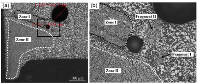
Figure 4 Interaction between bubbles and solidification structure under ultrasound treatment at 140W, b is the amplification of selected zone; c and d are the details of Zone II and frgment II respectively.
Interaction between bubbles and solidification structure
Dendrite fragmentation
Cavitation bubble is one of the most important phenomenon during ultrasound treatment process in casting. For the ultrasound treatment taken in experiment is from purring to solidification, so there are several cavitation bubbles survived. Figure 4a shows the area of sample corner connected to ultrasound probe and the quartz tube with a thin channel, and the detail information of the selected area is shown in Figure 4b. Two bubbles with size of 430μm and 95μm in diameter, and two different structure parts Zone I and Zone II were seen in Figure 4a, where Zone I located in the corner and fully filled the channel, and Zone II is near the top of Zone I. Zone I is typical lamellar eutectic structure and Zone II is the stripy structure mentioned before in Figure 4b. When the melt was purred into the tube, the probe was undercooled for the melt and then a thin layer with eutectic structure formed on the surface of the probe (Zone II) together with the formation of eutectic structure in the channel (Zone I). For Zone I is located in the corner with two boundary, i.e. quartz tube and probe, with a bigger super cooling degree, so microstructure is bigger. As the ultrasound turned on, the layer on the probe surface was blown away along with the streaming and broken into pieces, but the ultrasound effect in the corner is not strong enough to break the solidification structure in Zone I.
The effect of cavitation bubble on the formation of divorced eutectic
Figure 5 showed the microstructures around cavitation bubbles. In Figure 5a, there are two nonspherical cavitation bubbles with diameters of ~50 mm and 100 mm respectively. The microstructures around cavitation bubbles were separated Sn phase and blocky Bi phase. While, the microstructure far away from cavitation bubbles were typical eutectic. Similar phenomenon was also be seen in Figure 5b but with finer microstructure of both Sn and Bi phases. These were typical divorced eutectic structure, which usually happens in nonequilibrium situation, such as high cooling rate26 and microgravity.27 In this experiment, the solidification of alloy around cavitation bubble were under the effect of cyclic pressure induced by the oscillation of cavitation bubbles. The pressure change influenced the local melting point of melt according to Clausius–Clapeyron equation28
(1)
Where Tm is the liquidus at the atmospheric pressure P0. and are the volume change and enthalpy change during liquid–solid transformation, respectively. The temperature produced by cavitation bubble is up to several hundred degrees under the assumption of cavitation pressure at 1–5Gpa.28 Thus, the solidification around cavitation bubble was under nonequilibrium status. The microstructure of Sn–58wt.%Bi alloy without ultrasound treatment is Sn phase and eutectic, as shown in Figure 3a. Thus the Sn phase grew on the first precipitate Sn phase, with the Bi phase left in the crystal boundary, and finally divorced eutectic formed. For the effect of cavitation bubble is space–limited, the melt far away from cavitation bubble was normally eutectic.
Ultrasound treatment was introduced from bottom into Sn–58wt.%Bi melt. The microstructure of the solidified alloy was analyzed and the cavitation associated gain refinement was discussed:
The authors would like to thank the fund from Natural Science Foundation of China (Grant No. 51075299).
Author declares there is no conflict of interest.

©2018 Wang, et al. This is an open access article distributed under the terms of the, which permits unrestricted use, distribution, and build upon your work non-commercially.