eISSN: 2574-9927


Research Article Volume 2 Issue 6
1Department of Materials Engineering, Sahand University of Technology, Iran
2University of Tehran, Iran
3Nanjing University of Aeronautics and Astronautics, China
4Department of Materials Science and Engineering, Sharif University of Technology, Iran
5Department of Ceramics, Materials and Energy Research Center, Iran
Correspondence: Amirhossein Pakseresht, Center of Ceramic Coatings, Department of Ceramics, Materials and Energy Research Center, Karaj, Iran
Received: October 27, 2018 | Published: December 27, 2018
Citation: Alizadeh H, Hanaei A, Heidarshenas B, et al. The Effect of accelerator types on the phosphate Zn-%12Ni electrodeposite coating. Material Sci & Eng. 2018;2(6):224–229. DOI: 10.15406/mseij.2018.02.00062
The aim of this study is to investigate the effect of nitrate and nitrite on the weight, morphology and electrochemical properties of phosphate Zn-%12Ni electrodeposited coatings. In order to investigate the phase structure and surface morphology of samples, X-ray diffraction and scanning electron microscopy were employed. Also, to measure the corrosion resistance behavior of the coats, Potentiostat/Galvanostat test was used. The results showed that nitrite accelerator reduces coating weight and surface porosity simultaneously obtaining by phosphating solution. Furthermore, coatings being obtained by the nitrite accelerator had a higher corrosion resistance than that of the nitrate accelerator.
Keywords: phosphate coating, nitrate, nitrite, porosity, electrodeposite coatingAs the matter of steel corrosion protection, Zinc electrodeposits have been vastly engaged.1 These days, the corrosion resistance of conventional Zn coatings is not sufficient because the permanent industry requires (especially automotive and heavy duty applications like in hydraulic actuators) to reduce coating thickness and to increase the corrosion resistance of which at the same time. Therefore, extensive attempts have recently been made to develop highly corrosion resistant coatings on the steels and as a result, the conventional Zn coatings are being replaced by Zn alloys.2–7 Zinc-nickel, zinc-iron, and zinc-cobalt are the most widely utilized alloys for coating, even though zinc-manganese, appeared to have an excellent corrosion resistance, is not commercially available.8 It has been stated in several studies that corrosion resistance of electrodeposited Zn–Ni alloy coatings within a certain composition range (9–15 wt.%) can be significantly higher (5 to 6 times) than that of pure zinc.8–21 The useful lifetime of Zn and Zn alloy electrodeposits can be further increased by the formation of a passive film on their surfaces which can even be applicable in high frequency microwave structures.22–29 Chromate and phosphate films are common additional surface treatments used for various applications in different industrial fields.26,30–39 An excellent anticorrosive behavior of chromate films is well known; however, the toxicity of Cr (VI) compounds restricts the application of this technology.40 Phosphating is one of the most applicable processes carried out as a final surface treatment, although other methods like carburizing, nitriding and electrospary have been used.30,41,43 Phosphate coatings, because of their low cost, high phosphating rate, very high corrosion resistance, high wear resistance, and good lubricant and cohesion properties, have attracted important role in automotive industry.44 Short phosphating time is relatively an advantage for its application in industry. However, without any accelerator in the bath, the phosphating process would terminate in about 40 min. Therefore, such accelerators like nitride, nitrate, and chlorate should be added to zinc phosphate bath for accelerating and modifying the coating formation.44–49 In the acidic bath, nitrate and nitrite react with hydrogen ions. The nitrate reduction is:45
(1)
Nitrate in the bath and that produced by reaction (1) also has a reduction reaction like below:
(2)
On the ground that these two reactions consume H+ rapidly, the local pH increase at the metal-solution interface can increase and facilitate the precipitation of insoluble phosphate,45 quickly. In the present study, two phosphate baths were used for investigation of zinc nitrate and nitrite accelerator effects on the morphology and electrochemical properties of phosphate coatings.
For phosphate coating, cylindrical steel samples with 10mm diameter and 10mm thickness were used. The compositions of the samples are listed in Table 1. For surface preparation, the samples were ground with sandpaper No 240-1000 first and then mechanical preparation was done to achieve uniform and suitable surface. In order to remove pollutions, oil, and corrosion products, degreasing by 60g/l NaOH at 60-70oC temperature for 20 minutes, and acid cleaning in 30% HCl solution for 1 minute at ambient temperature were carried out. Finally, to form the Zn-12Ni coating on samples, a bath with chemical composition and working condition as shown in Table 2 was used. In this research, two phosphate baths were used. Components and the operating conditions of phosphate baths are shown in Table 3. In general, phosphate coatings are porous; however, these porosities can be reduced by Chromic acid or its salts as a final treatment. Hence, an aqueous solution with 0.015% chromic acid was used. After phosphating, samples were immerged in the mentioned solution for 15 seconds at room temperature. Figure 1 shows schematic of phosphating process steps. For phase structure study, X-ray diffraction (XRD) was performed with D8 advance diffractometer (Brokers) using Cu radiation (Cukα=1.54oA). The step-scan mode was 2–theta from 10° to 60° with a step size of 0.033°. The surface morphology of samples was investigated with CAMSCAN2300 Scanning electron microscopy (SEM). Coating weight as a main factor in determining the phosphate coating quality was measured for bath parameters and operating conditions standardization. The weight of the phosphate coating was determined by weighing the phosphated samples before and after stripping in 25g/l chromic acid solution for 2 minutes at 50oC temperature. The coating weight was calculated by applying the following equation:45
Elements |
Fe |
C |
P |
S |
N |
%wt. |
base |
≥0.17 |
0.04 |
0.04 |
0.009 |
Table 1 Chemical composition of the steels used for phosphate coatings
Solution |
Components (g/l) |
Temperature (oC) |
Time (min) |
Current density (A/dm2) |
|||
Zn-12%Ni |
NiCl2 |
ZnO |
NH4Cl |
Na4P2O7 |
20 |
8 |
15 |
|
5.59 |
14.35 |
160.47 |
133.82 |
|
|
|
Table 2 Components and the operating conditions of the bath for Zn-12%Ni coating
|
ZnO(g/l) |
H3PO4(cc/L) |
HNO3(cc/L) |
NaNO3(g/l) |
NaNO2(g/l) |
Solution 1 |
10 |
17 |
6 |
1 |
- |
Solution 2 |
11 |
18 |
7 |
- |
1 |
pH |
|
|
2.1-2.4 |
|
|
Temperature (oC) |
|
|
50±5 |
|
|
Time (min) |
|
|
10 |
|
|
Table 3 Chemical composition and operating conditions of the phosphating baths
(3)
In which w1, w2 are sample weights after phosphating and stripping in chromic acid, respectively. The corrosion behavior of phosphate coatings was investigated in a 3.5% NaCl solution at 25°C. In this regard, a standard three electrode system with a Pt counter electrode, a saturated KCL reference electrode and a sample with the area of 0.785 cm2 as working electrode were used. Samples were introduced into the cell system and allowed to reach open-circuit potential equilibrium (OCP) before electrochemical polarization measurements which took 1800s. Electrochemical polarization measurements were performed under potentiodynamic conditions; BEHPAJOOH BHP2063+ potentiostat/galvanostat with a potential scan rate of 0.001 V s−1. After reaching OCP, Samples were polarized between ±300 mV around OCP. The corrosion current densities (icorr) were determined by using the following equation:
(4)
In which icorr is the corrosion current density (A/cm2), ba and bc are the anodic and cathodic Tafel slope (V/dcad), respectively, and Rp is the polarization resistance (Ω). As the corrosion reactions initiate at the coating-substrate interface, the reduction of phosphate films with reduced porosity is appreciated. Determination of porosity is an important task in controlling the quality of phosphate films. This parameter could be estimated by applying electrochemical measurements and by determining oxidation and reduction rates on the sample surface. By considering the phosphate coatings electrochemically inert at low anodic over potentials, the porosity of coatings was calculated by using the following equation.33
(5)
Where F is the phosphate coating porosity (%), Rp.m is the polarization resistance of the bare Zn–Ni (Ω), Rp is the polarization resistance of the phosphate Zn–Ni electrodeposits (Ω), ΔEcorr is the difference in Ecorr of Zn–Ni electrode with and without phosphate layers (V), and ba is the anodic Tafel slope of the bare Zn–Ni electrodeposits (V/dcad).
X-ray diffraction patterns of the phosphated samples obtained by two phosphating solutions are shown in Figure 2. According to these patterns, phosphate coating contains hopeite (Zn3 (PO4)2.4H2O) and substrate (Ni5Zn21). Hopeite structure has a high adherence and corrosion resistance on the surface. SEM images of both phosphate coatings and Zn-Ni substrate without phosphate are shown in Figure 3. It can be observed that after phosphate coating, flower structure is formed on the surface. Hopeite structure looks like flowers50,51 and also XRD results are in agreement with SEM results, meaning this phase is hopeite. By comparing both phosphate coatings, It can be perceived that phosphate coating resulted by the second solution had finer grains than that of the first one which is attributed to the presence of nitrite in the second solution. Nitrite leads to an increase in the reaction and the nucleation rate and eventually, causes a decrease in grain size of zinc phosphate. As the grain size decreases, flower structure with fine grains is formed (reactions 1 and 2). In principle, the structure of inorganic phosphate coatings depends on their weight. Normally, light-weight phosphate coatings (0.2–1.4 g.m−2) have an amorphous structure, while middle-weight (1.4–7.5 g.m−2) as well as a heavy-weight (7.5–30 g.m−2) phosphate film demonstrate a crystalline structure52.
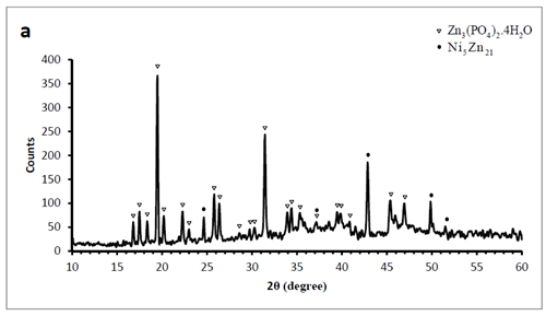
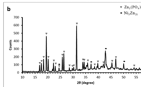
Figure 2 XRD patterns of the phosphate films on the Zn–Ni (12%) alloy surface. Coating produced by A) first solution B) second solution.
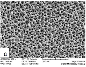
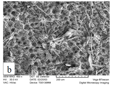
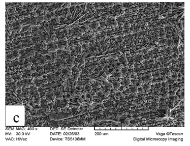
Figure 3 Scanning electron micrograph of Zn-Ni substrate A) without phosphate, B) with phosphate coating produced by first solution, and C) with phosphate coating produced by second solution.
Coating weight
At 50oC and 10 minutes of immersion, coating weights of 7.095 and 11.086 g/m2 were obtained for the second and first phosphate solution, respectively. Also as shown in XRD results, phosphate coatings produced by both solutions have a crystalline structure. It was proved from the values of weights that phosphate coating produced by the second solution has a lower weight than that obtained from the first solution. This weight difference is due to nitrite presence in the second phosphate solution. Nitrite increases the rate of phosphate reaction and decreases the amount of coating on the surface. By increasing the reaction rate, relatively uniform coating is formed on the surface. When the surface is covered by the coating, increase in the weight is not significant which is one of the conversion coating characteristics. In the acidic bath, nitrate in the first phosphate solution is reduced firstly, and then reduced nitrite from nitrate reduction reacts with hydrogen. In contrast, in the second phosphate solution nitride is present in the solution and this increases the reaction rate (Equations 1 and 2).
Corrosion behavior in a 3.5% NaCl solution
The corrosion behavior of Zn–Ni electrodeposits with/without phosphate coatings was evaluated by open-circuit (corrosion) potential (Ecorr) monitoring and polarization measurements, carried out in a 3.5% NaCl solution. The values of icorr and Rp were determined from polarization measurements. The obtained curves are presented in Figure 4 and the results are listed in Table 4. It can be seen from this data that the corrosion current density of Zn-Ni samples without phosphate coating is 2.551µcm-2. The ratio of corrosion resistance with phosphate coating to that without phosphate coating is 9.48 and 10.85 for the first and second solutions, respectively. Phosphate coating decreases the corrosion current density (icorr) and increases corrosion resistance in both solutions. The presence of hopeite structure on the surface as a suitable structure in phosphate coating causes an increase in the corrosion resistance of the coating. Also, it is noticed that the amount of icorr for phosphate coating produced by the second solution is lower than the first solution, and therefore, its corrosion resistance increases. Also, it is seen that icorr for phosphate coating produced by the second solution is lower than the first one, and eventually, the corrosion resistance of this coating is higher (Table.4). This behavior of the phosphate coating produced by the second solution can be explained by the fine grain structure of the coating. Surface of coating have a uniform and fine grain structure in the presence of nitrite. Likewise, surface porosity decreases, and hence, the contact between corrosive material and substrate was prevented, resulting in an increase in corrosion resistance.
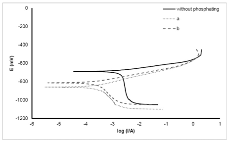
Figure 4 Potentiodynamic polarization curves of the phosphated and non-phosphated Zn–Ni alloy electrodes in a 3.5% NaCl solution at 25±2°C. Potential scan rate is 0.001 V s−1.
Phosphate coating type |
icorr (µA/cm2) |
Rp (kΩ).cm2 |
(-) Ecorr (mV) |
ba(mV/dcad) |
(-)bc (mV/dcad) |
ΔEcorr(mV) |
Without |
2.551 |
8.676 |
688 |
53.09 |
1237 |
- |
1 |
0.269 |
89.309 |
859 |
67.7 |
300.7 |
171 |
2 |
0.2351 |
87.678 |
812 |
56.03 |
308.5 |
124 |
Table 4 The electrochemical parameters (corrosion current icorr, polarization resistance Rp, the difference of Ecorr between Zn–Ni electrode with and without phosphate layers ΔEcorr, anodic and Cathodic Tafel slope ba, bc) of phosphate Zn–Ni alloy electrodes, measured in a 3.5% NaCl solution.
Coating porosity
After immersion in solutions at 50oC for 10 minutes, the porosity was %0.000519 and 0.0116 for the second and first solutions, respectively, which are lower than %1, showing the excellent quality of produced coats. The obtained values for the phosphate coating porosities are in the good agreement with the results of corrosion behavior of phosphate Zn–Ni alloy in 3.5% NaCl solution (Table 4). The obtained data indicate that the protective abilities of phosphate coatings on Zn–Ni electrodeposits in 3.5% NaCl solution depend mainly on their porosities. In general, it can be concluded that the lower porosity on the surface, the lower corrosion rate and the higher corrosion resistance of the substrate would be. Porosity in the coating obtained by the second solution is lower than that of the first solution which has to do with the presence of nitrite. Nitrite causes an increase in the phosphate reactions and insoluble phosphate production rates on the surface, resulting in a decrease in surface porosity.
The effects of nitrite and nitrate accelerators on the properties of phosphate Zn-%12Ni electrodeposited coatings were investigated. Hopeite Zn3(PO4)2.4H2O was the dominant structure in the phosphate coatings produced by both solutions. The type of accelerator had no effect on the obtained structure. Nitrite accelerator increases the formation rate of insoluble phosphate in comparison with nitrate, resulting in a low weight coating from nitrate solution. Compared to the coating produced by nitrate solution, the corrosion resistance of the coating obtained by nitrite solution is higher, notwithstanding lower weight value of the coating obtained by nitrite solution. Due to its low porosity value, the corrosion resistance of the coating obtained by nitrite solution is high. The protective properties of the phosphate coatings are related principally to their porosities. The low value of porosity is beneficial for the corrosion resistance enhancement since a phosphate layer acts as a physical barrier against corrosive agents.
None.
Authors declare that there is no conflict of interest.

©2018 Alizadeh, et al. This is an open access article distributed under the terms of the, which permits unrestricted use, distribution, and build upon your work non-commercially.