eISSN: 2574-9927


Research Article Volume 4 Issue 2
1Department of Mechanical and Aerospace Engineering, North Carolina State University, USA
2Department of Mechanical Engineering, University of Utah, USA
Correspondence: Mohammed Elamin, Department of Mechanical and Aerospace Engineering, North Carolina State University, Raleigh NC 27695, USA
Received: February 29, 2020 | Published: March 2, 2020
Citation: Elamin M, Varga J. Plate impact method for shock physics testing. Material Sci & Eng. 2020;4(1):31-35. DOI: 10.15406/mseij.2020.04.00123
This review article provides an understanding of the basic methods of performing plate impact experiments, as well as some modern innovations to the testing methods. Experimentalists today are able to study materials’ responses to shock loading with high precision and accuracy using a variety of plate propulsion methods, environments, and specimen orientations. The advancements have aided the development of material technology that resists shock loading for use in applications where these properties are critical to structural integrity and human safety.
Keywords: radioactive materials, high energy collision, plastic deformation, high temperatures, flyer plates
HEL, hugoniot elastic limit; LLVS, laser line velocity sensor system
Dynamic loading experiments under extreme testing conditions yield much different mechanical and chemical responses in materials when compared to those found under static conditions. Engineering applications of shock physics including ballistic and explosive impact, as well as any other sort of high energy collision, are found in a range of industries such as armor and weapons. The extreme temperatures and pressures at which shock physics experiments are able to test can simulate the response of radioactive materials during the detonation of nuclear weapons. It is therefore critically important to these industries to have an understand of the plastic response of materials at high temperatures and strain rates. An understanding of material responses is especially important for applications whereby shear bands are generated under extreme high strain rate conditions, such as in automotive and aerospace structures.1‒4 The foregoing serves as the motivation to investigate the appropriate experimental techniques that test the material responses to these conditions. One of the most common methods of investigating the behavior of materials subjected to a continuous deformation at high strain rates on the order of 105-107s-1 is to perform shear plate impact experiments.5‒7 In a general plate impact experiment, a gas gun launches a plate projectile towards a thin, circular specimen sandwiched between two additional plates.8 The flyer plate lies in between the projectile and the specimen, while the anvil plate lies behind the specimen. Often, the flyer plate itself is used as the projectile, making direct contact with the specimen. The projectile is guided by a key running through a keyway within the gas gun barrel, keeping it from rotating. A typical schematic of an experiment is depicted in Figure 1.
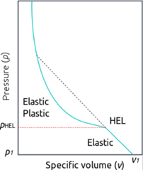
At impact, a pressure wave and shear wave are propagated into the flyer and the anvil plates. At this stage, the loading goes beyond the yield limit and the specimen experiences a plastic an nonrecoverable plastic deformation of approximately 2% due to the pressure wave.8 The pressure wave causes a force at the specimen-tungsten plate interfaces that provides sufficient friction to keep the specimen from slipping as it is loaded by the shear wave. Once the pressure wave reflects off of the far end of the rear tungsten plate and reflects back to reach the specimen, unloading occurs and the shear wave can no longer be transmitted through the specimen.8 In many experiments, the angle of each of the plates are adjusted uniformly with respect to the axis of the gas gun such that both normal and shear components of the pressure wave are created. The plates remain parallel to each other in order to maintain a uniform impact. Doing this allows researchers to study the response to different loading directions of the material in question.9 Of interest for applications involving shock-loaded materials is the Hugoniot elastic limit (HEL). The HEL is the pressure at which a material transitions from a purely elastic state to an elastic-plastic state. Above this limit, the material begins to act as a fluid, and loses much of its shear strength. Often, the stress-particle velocity curve of the specimen will show an abrupt drop at the HEL, attributed to a phase transformation within the material. The relationship between specific volume and pressure within a material above and below its HEL, called the Hugoniot curve, is shown in Figure 2. While a specimen subjected to static compression would fail far below its HEL, shock physics testing allows researchers to study this material phenomenon.10,11 The material response to these tests are most commonly measured using manganin gauges, either within the specimen or on its surface. These gauges are of a manganin alloy, which is a piezoelectric material generally consisting of 84% Copper, 12% Manganese, and 4% Nickel.10 Contrary to strain gauges, manganin gauges do not function by a change in resistance corresponding directly to the strain seen within the specimen. Rather, the piezoelectric alloy creates an electrical signal as a response to the pressure that the specimen is subjected to. The gauges are extremely thin, much like a foil, and are effective in measuring specimen stress in plate impact tests because of their low strain sensitivity and high-pressure sensitivity. A Wheatstone bridge measures and records the gauge output.10 A typical manganin gauge is depicted in Figure 3. Researchers proposed a novel pressure-shear plate impact experiment that consists of double-layer flyer configuration to analyze the dynamic response of metals undergoing high strain-rate testing.12,13 They concluded that the flow stress in metals is drastically increased as the test strain rate reaches a value of 105 s-1 and higher. It was also found that this increased sensitivity at high strain rates is due to an increase in strain hardening rate. Spall experiments are described in some detail later. Compressed nitrogen is used to accelerate a fiberglass projectile in the gun barrel. A reflective surface is created on the back of the anvil plate by placing an additional plate of polymethyl methacrylate there. This allows for the use of a laser interferometer, which takes velocity measurements of the anvil plate. Spall experiments test pure crystals of material that are embedded in a ductile binder alloy. Vogler & Clayton14 tested elongated spall at different crystal orientations within its binder. It was found that samples with the microstructure presenting the most area per unit volume in the direction parallel to the impact direction were stronger than those whose crystals were oriented perpendicularly.14,15 Ramesh and Kelkar at Johns Hopkins University16 developed a technique to measure the velocity of the projectile of a plate impact testing machine. As shown in Figure 4, the laser line velocity sensor system (LLVS) consists of an optical laser sheet generator, light collecting optics, and a holder. The motion of the projectile progressively allows diminishing light from the laser sheet to reach the photodiode of a collecting lens, onto which it is focused. The change in voltage over time due this change in the intensity of laser reacting with the photodiode can be used to calculate both projectile velocity and acceleration as a function of time. The output voltage response of a pressure-shear plate impact experiment on 6061-T6 aluminium samples is shown in Figure 5. The Nicolet 4049C digitizing oscilloscope is the source of the digital noise while taking the measurements. The accumulated light intensity on the collector is represented by the initial output, while the final output indicates the background intensity. Ramesh & Kelkar16 concluded that the LLVS is a cost-effective, accurate, and very efficient method of measuring the projectile acceleration. One difficulty in performing plate impact experiments is to achieve the high projectile velocities required without damaging the projectile itself, which is desired to remain within its elastic region throughout the test. Lemke et al.17 described method of achieving ultrahigh flyer plate velocities of 34km/s by means of magnetic acceleration. The current rise time was tailored to gain drive pressures of up to 490GPa on a 850 micron AL 6061 plate without inducing shock.

Figure 2 Relationship between specific volume and pressure within a material below and above its HEL.
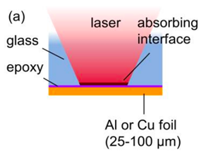
Another method of launching flyer plates on the scale of 0.5mm in diameter and 25-75μm thickness is by using a short, high energy laser pulse. Banishev et al.18 described a process of creating a nanosecond long high energy laser pulse in order to launch aluminum and copper flyer plates. A foil is positioned on the back of the flyer plate and becomes a rapidly expanding plasma upon being struck by the foil. The rapid expansion of the foil drives the flyer plate forward. A major concern of the laser propelled flyer plate method is after launch, the laser continues to act on the flyer plate, liquefying part of it throughout its motion. This causes the plate to lose mass, introducing high variability into the equations of state involving the conservation of momentum, and destroys the flyer plate during each test.18,19 Banishev’s group18 has constructed a flyer plate configuration that allows for it to be launched by the laser while at the same time shielding it from the laser pulse after it has been launched. Figure 6 shows the construction, which consists of the foil bonded to a borosilicate glass substrate by an epoxy layer. The laser is mostly absorbed locally at the glass/epoxy interface, denoted as the absorbing interface region. Shock is induced in this layer of the glass, aiding in propelling the flyer disks, while the entire glass substrate acts to allow only a small fraction of the incident pulse to be transmitted through it and onto the flyer plate. It was using this method gave the flyer plate the same flight characteristics as conventional methods.18,20 Frutschy and Clifton experimentally investigated the dynamic behavior of OFHC copper at high strain rates of 105-106s-1, and temperatures up to 700°C.21 The time-distance diagram of the experimental setup is illustrated in Figure 7. The specimen, which takes the shape of a thin foil, is placed under high-temperature tungsten carbide plates. It is important that these plates remain elastic at the high temperatures at which testing takes place. Any misalignment which may take place due to thermal expansion of components within the system are measured by the reflection of a laser off of the back end of the rear plate.

Figure 6 Banishev et al.18’s foil/flyer plate interface.
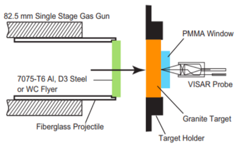
The misalignment is corrected using a remote control to orient the plates such that the correct alignment with the face of the projectile is achieved. An induction heating coil is wrapped around the specimen as shown in Figure 8, and the frame holder contains the ceramic holder that supports the specimen foil. To isolate the heating coil during the experiment, the coil is designed to be larger than the projectile tube. The results from Frutschy and Clifton’s experiments21 showed that the OFHC copper samples experience strain rate sensitivity of 2.5-14 x 105s-1 in a wide temperature range of 300-700°C. Yuan & Prakash22 developed a unique plate impact experiment to study the shock-induced response of granite rocks. Their experimental setup includes plate impact spall experiments (Figure 10), and soft recovery plate impact experiments (Figure 9). Soft recovery experiments allow the anvil plate to separate from the specimen once the pressure wave reaches its end in order to prevent the specimen from being reloaded after the incident pulse. This is desirable when the effect on the microstructure of the primary pressure wave alone is to be examined Results of Yuan and Prakash’s work show that the tensile fracture in granite samples is dependent on the duration of loading and that the tensile wavelength governs the maximum strength. Furthermore, they observed the growth of cracks and holes on the spall plane at higher magnifications. The cracks are initiated at weak grain boundaries and continue to propagate, causing brittle failure of the samples.

Figure 9 Yuan & Prakash22 plate-impact spall experiment.
This paper has provided a review of both some of the basic methods of performing plate impact experiments, as well as some modern innovations to the testing methods. Experimentalists today are able to study the material response to shock loading with high precision and accuracy using a variety of plate propulsion methods, environments, and specimen orientations. The advancements have aided the development of material technology that resists shock loading for use in applications where these properties are critical to structural integrity and human safety.
None.
Authors declare that there is no conflicts of interest.

©2020 Elamin, et al. This is an open access article distributed under the terms of the, which permits unrestricted use, distribution, and build upon your work non-commercially.