To compute the magnetic dipole of a spherical nanoparticle we use the following equation:55,56
(1A)
Where, , χ and are magnetic dipole nanoparticle, the radius of them, magnetic susceptibility, and the amplitude of the external magnetic-field, respectively. The magnetic force of the spherical particle of Eq.1-a is:56
(1b)
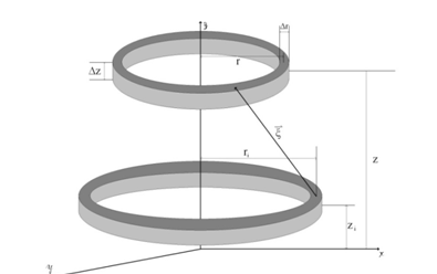
In Eq.1-b, is the magnetic force on the particle with magnetic dipole of from external magnetic-field. In order to calculate the magnetic dipole of a nanowire numerically, we firstly defined a cylinder and generated a mesh on it to describe the model parameters. For this purpose, we divided the cylinder into discs and then divided every disc to a number of rings. Figure 2 shows the schematic picture of the mesh for a nanowire in cylindrical coordinates. In this model, we consider a single super paramagnetic nanowire in a constant external magnetic-field and then calculate the magnetization and the magnetic dipole of the wire. The correlation between magnetization and magnetic current is as follows:

Figure 2 Meshes schematically generated on wire.
(2)
Where is the vector of magnetization, and is the magnetic current density. The boundary condition for Eq.2 is expressed as follows:
(3)
In which, is the surface magnetic current density and is the vertical vector at wire surface.
For magnetic field intensity without free current, we have:
(4)
The relationship between magnetization and magnetic-field and linear magnetization with respect to is defined as:
(5)
The combination of (5) and (6) yields to:
(7)
Eq.4 and 6 yield to:
(8)
Now, we should calculate magnetic-field in every point of the wire. For this purpose, we have used superposition principal of vectors, like:
(9)
Bother elements is the sum of all magnetic-fields that are generated with magnetized nanowire elements. Eq.10 shows Bother elements components in the wire with considering Eq.2, 3 and 8:
(10)
Bi is the magnetic field of superficial current for jth ring on the surface and p is the number of superficial rings. In order to compute the magnetic field originated from the surface current on the external surface of wires, the rings shown in Figure 3 are considered. In this figure, ri and zi are radius and height of the ring on the external surface of the wire with superficial current density and r and z are the coordination of the point of interest to compute its magnetic field. In wire, we have three kinds of external surfaces: down, top and side. The surface current for all three surfaces are calculated as follows:

Figure 3 Schematic representation of the wires and their respective coordinates.
(11)
(12)
(13)
According to Biot– Savart law, the magnetic field of ith surface ring (Bi) in point (r, z) is expressed as follows:
(14)
In which, is the distance vector from every point on the ring to point(r, z) and the integral is on the environment of the ring with center (0, zi). For simplification, we write the following equation:
(15)
Then we can rewrite the Eq.14 according to the Eq.15:
(16)
From Eqs.10, 11, 12, 13 and 16, we have:
(17)
Where k is the number of the rings and is the magnetic field in kth ring.
If we write the Eq.17 on radial and vertical directions, we will have:
(18)
(19)
Where andare vertical and radial components of the magnetic field in each ring, and and are vertical and radial components of Eq.15. If we apply Eq.7 into Eqs.18 and 19, the final equations can be obtained:
(20)
(21)
Now, we have two series of variables: and. If we write Equations 20 and 21 in every n rings of the wire, we will get 2n equations as n rings become magnetic on both vertical and radial directions and a specification matrix with size 2n×2n for magnetization of the wire. Equation 22 shows the relationship between the variables:
(22)
If we suppose B01 and solve the equations, we can obtain magnetization matrix for every B0 such as follow:
(23)
Where is magnetization matrix for external magnetic field and is magnetization matrix for B0=1. The magnetic field of the cylindrical magnet is expressed as follows:56
(24)
Where and d are magnetic field and diameter of the cylindrical magnet, respectively.
The magnetic field gradient of a cylindrical magnet is expressed as:
(25)
With attention to the Eq.1-b, 24 and 25, the magnetic force is related to d as follow:
(26)
Considering the Eq.26, we can compare the depth of magnetic targeting according to:
(27)
Where dw and ds are the depth of magnetic targeting for wires and spherical particles, respectively. The parameters mw and ms are magnetic dipoles of nanowires and spherical particles.
To compare the magnetization and the magnetic dipole of the spherical and the cylindrical nanoparticles, we use the corresponding parameters in a uniform unit magnetic field. Table 1 shows different specifications used for simulation in this research. With the parameters shown in this table, 175 combinations exist. We chose these combinations to show the effect of geometry on magnetic force and the depth of magnetic targeting. Changing the aspect ratio (α) at a constant volume results in the variation of radius and the height of the wire. For every sphere with radius of r, the volume is calculated and then for every α, the radius and height of the corresponding wire are calculated and then the magnetization and the magnetic dipole of the wire is simulated at different susceptibilities. (Figure 4) (Figure 5) show the magnetization in vertical and radial directions with radius r30 nm and α5. Figure 5 shows the magnetic dipoles of wires in the vertical direction for different sizes with various aspect ratios and different susceptibilities. Radius and height of the wire are calculated from the following equations as a function of α:

Figure 4 Magnetization of a wire with r=30 nm, α=5 and susceptibility=500: (A) magnetization in the vertical direction and (B) magnetization in the radial direction.

Figure 5 Vertical magnetic dipole of the nanowire versus the ratio α at different susceptibilities for rs equal to: (A 15nm, (B) 30nm and (C) 50nm.
Parameter |
Quantity |
Radius, m |
15×10-9 |
30×10-9 |
50×10-9 |
80×10-9 |
100×10-9 |
|
|
Aspect ratio (α) |
1 |
2 |
3 |
4 |
5 |
6 |
7 |
Susceptibility |
20 |
500 |
1000 |
1500 |
2000 |
|
|
Table 1 Specification of the nanowires used for simulation.
(28)
(29)
(30)
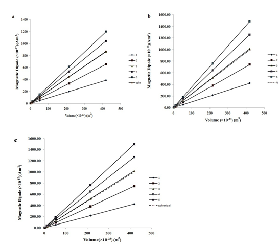
V is the volume of the spherical particle with radius rs. R and L are the radius and length of the corresponding nanowire. In Eqs.28, 29 and 30, it is assumed that the volume of the wire and the spherical particle are the same. Then, for all aspect ratios, radius and height of the wires were calculated. As shown in Figure 5, it is clear that increasing the susceptibility from 500 to 2000 has no influence on the vertical magnetization, being also the same for spherical magnetization. Instead of materials with high susceptibility, we, therefore, chose materials with high saturation limit. This will result in more magnetization without saturation. Figure 6 shows that vertical magnetic dipole of the nanowires with respect to their volume is linear. Likewise, the magnetic dipole of spherical particles is linear. The slope of graphs increases as the aspect ratio increases. At α=3, the behavior of wires and spheres is the same. More increase in the aspect ratio up to 5 retains the double magnetic dipole at a constant volume. It is clear that magnetic dipole increases with α, directly; however, if α is more than 5 or 6, the mechanical solidity of wires will decrease. In this research, we can increase the magnetic dipole of the particles merely by changing their geometry. Comparing the magnetic dipole of a wire having α=5 and radius =15 nm with a spherical particle of radius =15nm, we found out that the magnetic dipole of the former is 15 times larger than that of the latter. This means that if we use a wire with specifications above, the magnetic force will be 15 times greater than the corresponding spherical particle. When using nanowires, we can increase the volume without increasing their radius and simultaneously increase the magnetic dipole merely with α enhancement. These two specifications can be used to increase the depth of target and diffusion rate of the drug carrier particles toward the tumors without increasing the radius of particles. Figure 7 shows the magnetic dipole of nanowires and spherical particles as a function of susceptibility at different α ratios for radii 15, 30 and 50nm. As was shown in the mentioned figures, the relationships for wires of α=3 are similar to the spherical particles while increasing the susceptibility of the magnetic materials above 500 has no independent influence on the magnetic dipole.

Figure 6 Magnetic dipole versus volume of nanowires and spherical particles for different aspect ratios at susceptibility equal to: (A) 20, (B) 500 and (V) 2000.

Figure 7 The magnetic dipole of wire and spherical particles versus susceptibility at various aspect ratios and rs equal to: (A) 15nm, (B) 30nm and (C) 50nm.


