eISSN: 2574-9927


Research Article Volume 3 Issue 3
1Tsinghua University, China
2 Beijing e-Plus 3D Tech. Co. Ltd, China
Correspondence: Jinwu Kang, School of Materials Science and Engineering, Key Laboratory for Advanced Materials Processing Technology, Tsinghua University, Beijing 100084, China
Received: June 24, 2019 | Published: June 26, 2019
Citation: Kang J, Dou Z, Deng C, et al. Effect of heat treatment on the microstructure and hardness of the SLMed TC4 alloy specimens. Material Sci & Eng. 2019;3(3):82-87. DOI: 10.15406/mseij.2019.03.00096
Titanium alloy TC4 owns a series of advantages such as light weight, high strength-weight ratio, high strength at high temperatures, resistance to corrosion and etc., which makes it suitable for aerospace industry. Selective laser melting process provides a good manufacturing method of titanium alloy parts as an alternative way to avoid the disadvantages in casting and forging. The layer by layer forming way in SLM leads to unique microstructure. The microstructure of SLMed TC4 alloy specimen was investigated. The samples were treated by annealing and solutionizing-aging respectively. The effect of annealing temperature, solution temperature and aging temperature and time on the microstructure and hardness were studied.
Keywords: selective laser melting (SLM), TC4 alloy, heat treatment, microstructure, hardness
Titanium alloys have outstanding properties such as corrosion resistance, high strength-to-weight ratio even at high temperatures, which makes them a suitable candidate for high demanding applications such as in aerospace industry. Among the Ti-alloy families, Ti-6Al-4V(TC4) has been widely used in additive manufacturing as well as traditional processing such as casting and forging. Additive manufacturing can be used to fabricate titanium alloys with complex geometrical features and reduce material waste, production time and costs. There are many researches about the effect of heat treatment on as-cast or as-forged microstructures.1,2 As additive manufacturing appears, the microstructure features and the effect heat treatment on the additive manufactured specimens come to be the research focus. Jiao et al.,3 found that α laths have a plate morphology, and they precipitated out from β phase following a tetrahedral relationship, a special morphology with mixture of plate-like and rod-like α phase in the fabricated Ti-10V-2Fe-3Al alloy specimen by laser melting deposition additive manufacturing. Aziz4 &Murr5 Thijs6 & Kobyrn7 & Zhu8 & Song9 investigated the microstructure of TC4 titanium alloy in selective laser manufacturing. SL Med samples own good mechanical properties except of ductility. Thus, researchers investigated the way how to improve the ductility by heat treatment. Erhard10 studied the effect of heat treatment on the microstructure and mechanical properties of samples made by SLM. Sabban11 proposed repeated thermal cycling close to but below the β transus temperature to form globular α phase, eliminating the need for plastic deformation prior to heat treatment, which led to the bimodal microstructure consisting of globular α in additively manufactured TC4 alloy. In order to provide the understanding how to improve the mechanical properties, the TC4 titanium alloy samples were made by SLM method and they were heat treated, the effect of heat treatment on microstructure was symmetrically investigated.
TC4 alloy powder ranging from 15~45μm was used in the fabrication of specimens. The powder, purchased from AP&C company, was made by plasma atomizing method according to ASTM B348 grade 5. The observed powder profile by EBS method is shown in Figure 1. Its chemical composition is listed in Table 1. Cylindrical bars of size φ 30mm×150mm were fabricated by an EP-M250 3D printing machine equipped with a 200W Yb-fiber laser beam (made by Beijing ePlus 3D Technology Co. Ltd). The fabrication parameters such as laser power, scanning speed, hatch distance, layer thickness are listed in Table 2. Unidirectional scanning strategy was adopted, with the scanning direction rotated 90° clockwise for next layer. The fabrication process is under argon atmosphere. Two cylindrical bars, No.A φ 4.4mm×20.8mm, and No.B φ 3.1mm×23.6mm with the length in the building direction, were cut from center of the fabricated bar. No.A is further cut into six segments designated as A1-A6 along axis and specimen B into 2 parts numbered as B1 and B2 vertically by electrical discharge machining method for microstructure and micro hardness test. These samples were heated treated in KSL1200X shaft furnace. The heat treatment schedule is listed in Table 3. Samples were treated by two kinds of heat treatment schedules, annealing at four temperature levels, 780°C, 970°C, 1000°C and 1100°C and cooling down in furnace, and solutionizing at 940°C, water quenching and then aging at different temperature levels and time span, 450°C, 500°C and 650°C for 3 or 4hours. These heat treated samples were ground by a series of sand paper ranging from 400# to 7000#, then polished, cleaned by anhydrous ethanol, etched by Kroll agent and finally cleaned by ultrasound cleaning, anhydrous ethanol and acetone agents. The microstructure was observed on 6XB-PC optical microscope and JSM-7001F SEM microscope. Their hardness was measured by HV1000Z tester. Four points were measured and the averaged value was used.
Al |
V |
Fe |
C |
O |
N |
H |
Ti |
5.50-6.75 |
3.50-4.50 |
0.05-0.25 |
0.02 |
0.14-0.16 |
0.02 |
0.010 |
Bal. |
Table 1 Chemical composition of TC4 Powder (wt.%)
Items |
Value |
Power |
200W |
Scanning speed |
7m/s |
Hatch distance |
0.08mm |
Layer thickness range |
0.02mm |
Atmosphere |
N2, O2 <100ppm |
Table 2 Fabrication parameters
Sample |
Heat treatment |
Parameters |
|
Temperature (°C) |
Time(h) |
||
A1 |
Annealing |
780 |
1 |
A2 |
Annealing |
970 |
1 |
A3 |
Annealing |
1000 |
1 |
A4 |
Solutionizing and aging |
940 |
1 |
650 |
4 |
||
A5 |
Solutionizing and aging |
940 |
1 |
500 |
4 |
||
A6 |
Solutionizing and aging |
940 |
1 |
450 |
4 |
||
B1 |
Annealing |
1100 |
1 |
B2 |
Solutionizing and aging |
940 |
1 |
650 |
3 |
||
Table 3 Heat treatment schedule
The as-fabricated microstructure is shown in Figure 2. The microstructure is α′phase, bundles of parallel bundles of fine needles in different directions, in the β phase matrix. During the solidification process, the melt first transformed to β phase in large grains, and then α’ phase formed directly inside β phase grain without the diffusion of alloy elements because of fast cooling during fabrication. α’ phase, a hexagonal-closed packed (HCP) structure, is martensitic profile.
Effect of annealing
The microstructures at the horizontal section under different annealing temperatures are compared in Figure 3. As the sample annealed at 780°C the microstructure undergone less change because of low annealing temperature which is far lower than the β phase transformation temperature 980°C12 of TC4 alloy. There is no β phase transformation, α’ phase became thicker and turned into α lath phase, but they were still very long. As the sample was annealed at 970°C close to the β phase transformation temperature, the microstructure turned into the typical basket-weave profile with α short lath bundles in different directions weaved, and a few short α laths appeared along the grain boundary. The SEM figure shows the α lath and the β phase in between them. Its lathe width is around 4μm. As the sample was annealed at 1000°C, a little higher than the β phase transformation temperature, the microstructure appeared to be bimodal, α thick laths along the boundary of β phase grains and the basket-weave α pattern in β grain. The thickness of the α lath is around 20μm, while the α phase of the basket-weave pattern is only around 10μm. As the sample was annealed at 1100°C, it consists of the grow-up primary α laths and the α laths transformed from β phase, both of them are with similar width of around 25μm and 70μm long. The microstructure of coarse α phase and the secondary α phase in β matrix are proved to own good comprehensive mechanical properties, thus, annealing at 1000°C is recommended in this paper.
Effect of solutionizing and aging
The microstructure of the samples solutionized at 940°C for 1 hour and then aged at different temperatures for 4hours were shown in Figure 4. All of them appeared to be basket weave pattern α phase in β phase matrix. However, the high aging temperature is, the finer the α laths are. The width of the α lath are around 1μm, 2μm and 3μm. Higher aging temperature facilitates the diffusion of alloy elements and then leads to the appearance of fine α laths. The effect of aging time on the microstructure is shown in Figure 5. As the sample was aged for 3 hours, there is primary α lath and secondary α lath. For the solutionizing temperature is close to but not higher than the β phase transformation temperature, thus there is no β phase transformation. But the fine martensitic structure can change directly into coarse α lath, which is mentioned in the reference.1 And some α phase transformed into β phase, then fine α laths deposited in the β phase during aging, which was called secondary α phase. The thick α laths and the secondary α phase in β matrix is called bimodal phase pattern. However, for the aging of 4 hours no secondary α phase was observed.
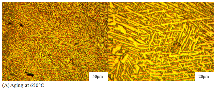
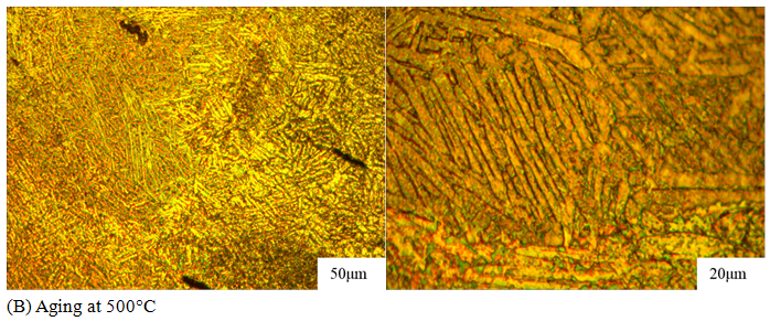
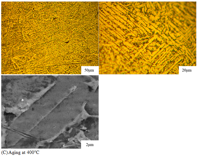
Figure 4 Microstructure of the samples solutionized at 940°C for 1hour and then aged at different temperatures for 4hours.
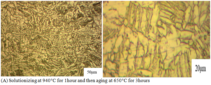
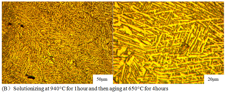
Figure 5 Microstructure of the samples solutionized at 940°C for 1hour and then aged at 650°C for different time.
Effect of heat treatment on micro hardness
The micro hardness results are listed in Table 4. All of heat-treated samples own higher micro hardness than the as-fabricated state. The micro hardness of these samples increased a little after annealing, the higher annealing temperature, the greater the micro hardness, as shown in Figure 6A. The hardness is closely related to the percentage and size of α and β phases. In the basket wave microstructure, there is mainly α phase but with small size. The hardness increased as bimodal phases appeared at higher annealing temperature. For the microstructure annealed at 1100°C, the bimodal profile is not very clear, so, the hardness reached a platform. It increased significantly after solutionizing and aging, the lower aging temperature, the greater the micro hardness, as shown in Figure 6B. During solutionizing, the alloying elements sufficiently diffused into the matrix structure, so the hardness was greatly increased. But during aging, the higher temperature, the finer α phase appeaed, therefore, the micro hardness decreased with the increase of aging temperature.
No. |
Heat treatment |
Micro hardness(Hv) |
1 |
no |
382.71 |
2 |
Annealing at 780°C |
386.98 |
3 |
Annealing at 970°C |
395.72 |
4 |
Annealing at 1000°C |
403.90 |
5 |
Annealing at 1100°C |
404.25 |
6 |
Solutionizing and aging at 400°C(4h) |
434.55 |
7 |
Solutionizing and aging at 500°C(4h) |
419.09 |
8 |
Solutionizing and aging at 650°C(4h) |
405.35 |
Table 4 Micro hardness results
The effects of heat treatment on the microstructure and micro harness of the cylinders fabricated by selective laser melting were investigated.
This research study was funded by the National Science and Technology Major Project of the Ministry of Science and Technology of China under Project No. 2016YFB1100703.
Author declares that there is no conflict of interest.

©2019 Kang, et al. This is an open access article distributed under the terms of the, which permits unrestricted use, distribution, and build upon your work non-commercially.