Magnetic diploe moment can be modeled in a similar manner to a loop of wire carrying current i. Energy stored in that dipole moment can be obtained by integrating the torque produced by that current carrying current loop. The summation of magnetic dipole moment over the volume Δv yields a new property of material called magnetization. The property of aligning domains within a permanent magnet itself with its internal field and in absence of external field is called spontaneous magnetization. In other words, a permanent magnet should sustain flux by virtue of its own internal field that requires spontaneous alignment of the magnetic dipole moments, or spontaneous magnetization. Magnetic materials are made in such a way that they have properties in one preferred axis that is easily possible using anisotropic materials because of their lattice structure. MagnetoCrystalline anisotropy energy refers as the change in energy required to rotate the magnetic dipole µm by an angle ɸ that is required to rotate µm from a preferred axis (ɸ=0). Body centered cubic crystal lattice structure with six preferred direction of magnetization is depicted in this paper.
The torque developed by a small area depends upon the area of the strip and its magnetic flux density.
(1)
Integrating the equation 1
(2)
Current time’s area in a magnetic circuit can be symbolized as the Magnetic Dipole Moment.
The energy constituted within a dipole having torque ‘T’ can be derived from the equation (3)
(3)
(4)
The energy obtained from a magnetic dipole assuming it to be a current carrying loop is obtained as in equation (4).
Some of the materials itself has preferred directions for magnetic moments.These alignments of the magnetic dipole moments in the lattice is called magnetocrystalline anisotropy. Equation (4) implies that the work done to rotate the µm with magnetization ‘M’. This work done is minimum when µm and M are aligned to each other.
Equation (4) can be written as;
(5)
MagnetoCrystalline Anisotropy Energy Ek can be defined as the additional energy required to rotate µm from a preferred axis (ɸ=0).
(6)
There are six preferred direction of magnetization in a body centered cubic crystal lattice.
[0, 0, 1] - Positive z direction
[0, 1, 0] - Positive y direction
[1, 0, 0] - Positive x direction
[0, 0, -1] - Negative z direction
[0, -1, 0] – Negative y direction
[-1, 0, 0] – Negative x direction
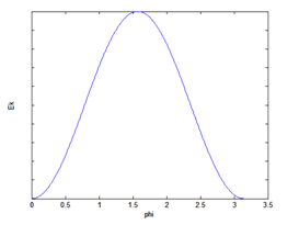
In order to increase the periodicity in equation (6), we modify the equation (6) as (Figure 1);

Figure 1 Magnetocrystalline anisotropy energy in a cubic crystal lattice structure.
(7)
Plot for equation (7) is provided below; Equation (7) can be represented as
(8)
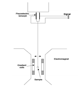
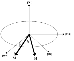
Here, k is commonly described as a crystallographic constant that is experimentally identified using a tool called torque magnetometer (Figure 2). Magnetocrystalline Anisotropy tries to maintain the alignment of its domains whereas the external electromagnets try to oppose the anisotropy. These two forces create a torque that is measured by the magnetometer. The data from the device can be used to obtain the crystellographic constant of a material. The action of two forces creating a net torgue is shown in the Figure 3. Considering a bulk of iron sample that is already spontaneously magnetized in its posative x axis direction or simply towards [1, 0, 0]. But whenever a sufficient external magnetizing field is applied to the sample then all the magnetic moments would align along with the magnetizing field of the electromagnet. Assuming Φ to be the angle of saturated magnetic field ‘M’ of the sample with posative x axis and Φh be the angle of the magnetizing field ‘H’ with posative x axis [1, 0, 0]. The component of M that acts along the direction of the applied field H is given as

Figure 2 An illustration of magnetomenter.

Figure 3 Illustration of Magnetization force (M) of the sample and the magnetizing field force of the electromagnet (H).
(9)
Here, is the component of saturated magnetic field M along the direction of applied field H. Applied field energy per unit volume after when H is at an angle of is given as
(10)
Now, the total energy stored in the sample will be the sum of and . So, adding equations (8) and (10), we get
(11)
Differentiating the equation (11) in order to obtain the minimum total energy.
(12)
The intrinsic coercivity of a material is the value of H that causes M to suddenly reverse in opposite direction.
This intrinsic coercivity can be obtained by differentiating equation (12).
(13)
For total reversal, the angle is 180o
At, =0,
=0
Therefore, equation (13) is reduced to
(14)
is the intrinsic coercivity. Equation (14) provides a measure of the direct external demagnetization force that a sample can withstand.
The above plot in fig.1 demonstrates that the unstable condition for µm lies at an angle of π/4. Other elements used in permanent magnets may have complex lattice structure. This model for cubic crystal structure is of iron. This process helps to understand the basics of magnetic characteristics. Similarly, brief– knowledge can be extracted about the intrinsic coercivity or maximum demagnetization force that a sample can withstand.1–3
None.


